Note: Descriptions are shown in the official language in which they were submitted.
Doc. No. 318-23 CA
Greentech
A METHOD OF ACCELERATING OXYGENATION OF A BODY OF WATER
Field
This disclosure relates to a method and system for accelerating oxygenation of
water in a body
of water.
Background
Oceans, lakes and ponds provide essential resources for a wide range of
species of terrestrial
and organic organisms, and such water bodies require oxygen-enriched water to
support life.
The structure and function of ponds and lakes are determined by factors such
as turbulence,
temperature, and water depth. Wind turbulence and temperature interact to
influence
stratification and water circulation within lakes and ponds.
At certain times of the year, for instance in the spring, wind turbulence
circulates the water
throughout a lake supplying oxygen to the entire water column throughout its
depth.
Notwithstanding, as the temperature increases during the summer and wind
subsides, thermal
stratification occurs, producing distinct layers in the water column; the
upper warm-
water layer is separated from the lower cold-water layer by a thermocline. A
thermocline is a
distinct layer in a large body of water, such as an ocean or a lake, where the
temperature changes
rapidly with depth. In most cases, the temperature decreases with increasing
depth in the ocean.
The thermocline separates the warmer, well-mixed surface layer (epipelagic
zone) from the
colder deep water below (mesopelagic and bathypelagic zones). The thermocline
is important
because it acts as a barrier to mass transfer and convective heat transfer
between the surface and
deep layers of the ocean. This stratification has significant implications for
marine life, ocean
circulation, and weather patterns.
A halocline is a layer in a large body of water characterized by a rapid
change in salinity with
depth. Salinity refers to the concentration of dissolved salts in water. In
oceans, the surface layer
has relatively lower salinity due to freshwater inputs from rivers, melting
ice, and precipitation.
As one goes deeper into the ocean, the salinity usually increases. A halocline
separates the less
1
Date recue/Date received 2024-01-30
Doc. No. 318-23 CA
Greentech
saline surface water from the more saline deep water. Like the thermocline,
the halocline also
affects ocean circulation and can create barriers to the vertical mixing of
water masses.
Temperature and salinity are the two primary factors that influence the
density of seawater. Cold
water is denser than warm water, and water with higher salinity is denser than
water with lower
salinity. The combination of these two factors results in different water
masses with varying
densities. The thermocline and halocline influence the density of water in
their respective layers.
Density variations play a crucial role in ocean circulation and vertical
mixing. In some regions,
the thermocline and halocline can interact, affecting the overall water
column's stratification
and circulation patterns. In summary, thermoclines and haloclines are both
transition zones in
the ocean and coastal water, defining changes in temperature and salinity,
respectively. These
transitions have significant effects on density and can impact various oceanic
processes and
ecosystems.
Oxygen concentration of the water in the lower layer tends to decline compared
to the upper
.. layer as a result of a lack of water circulation. Without mixing to
replenish dissolved
oxygen, respiration by organisms within the lower layer may further reduce
oxygen
concentrations.
In aquaculture, heavy-oxygen-enriched water is required; as a result,
oxygenating machines
have been used to disturb the surface of the water and facilitate oxygenation.
Some of these
machines are more energy efficient than others. These machines include
aerators, bubblers and
agitators and within these three classes of devices or machines there are many
tens of sub-types.
What most of these machines have in common is the consumption of significant
power to run
them. There are other drawbacks as well; for example, water wheels and other
machines that
launch water into the air to oxygenate increase evaporation of the water that
they are
oxygenating. Furthermore, they primarily affect water near the surface.
Aerator and agitator
type devices described in U.S patent application in the name of Parker et al.
US 202101480 and
Chinese Patent in the name of Jian CN20098805 describe devices that rotate at
very high
speeds, for example 900-1800 RPMs and consume considerable power.
2
Date recue/Date received 2024-01-30
Doc. No. 318-23 CA
Greentech
Another type of device which is not per-say and an aerator or an agitator, and
which may be
powered with solar panels, using minimal power, is a radial flow water surface
spreader
(RFWSS). A radial flow water surface spreader, sometimes referred to a as a
biofan, comprises
of a floating mechanical device which imparts a horizontal radial force on the
water surface
with preferably minimal or no vertical force components to conserve the energy
required to
achieve the maximum range of impact on the water surface. Consequently, it is
preferable that
this device does not impart any vertical force vectors or local component
mixing, i.e., its primary
function is not that of water mixer or a mechanical aerator. Its primary
function is that of a
water mover. The radial flow water surface spreader generates a radial bulk
circulation of the
affected waterbody without any significant local component mixing. Although
the RFWSS
performs oxygenation well during daylight hours, its success, commercially,
has been very
limited and in fact many of these RFWSS devices are today considered
functionally inadequate
and many are no longer being used. By using an RFWSS a significant drawback
occurs when
the sun is not present, for example during the night. The way in which the
RFWSS works is that
as its paddles gently rotate at a very slow speed and move the surface water
around the device.
The radial outward flow of the surface water generates a water "conveyor belt"
with minimum
local mixing. This water conveyor belt loops back to the lower water layer
because of the
hydraulic suction created by the upward movement of the water immediately
underneath of the
RFWSS to fill the gap left by the outward moving water surface layer.
Conveniently
thermoclines are diminished and consequently, the phytoplankton and the
hypoxic water at the
lower depths of the waterbody are brought up to the surface. The exposure to
the solar radiation
at the surface permits these phytoplankton to grow through photosynthesis
which releases
oxygen into the water. As a water mover, the RFWSS is a poor mechanical
aerator which
depends on high turbulence generated by high-speed rotating blades to produce
large areas of
water/air interface to achieve its high rate of oxygenation. The RFWSS
achieves water
oxygenation differently, through the oxygen released in the photosynthesis
process. This
circulation which is primarily via moving rather than mixing permits more
phytoplankton to
grow (biological productivity) throughout the whole waterbody within this
water circulation
loop. However, this higher phytoplankton population stops generating oxygen at
night when
there is no photosynthesis and its respiration consumes more dissolved oxygen.
Without an
3
Date recue/Date received 2024-01-30
Doc. No. 318-23 CA
Greentech
effective pathway to bring more oxygen from the air into the water, the
waterbody, especially
the lower depths, turns hypoxic at night and this is highly problematic.
An entirely different device is known, which effectively and with very low
power increases the
oxygenation of water bodies. U.S. patents 10,934,186, 10,875,794, 10,737,796
and 10,767,021
all in the name of Parisien et al., describe this device which promotes
oxygenation of large
bodies of water by using a suitably programmed signal generator coupled to a
transducer which
provides a signal which transmits a alternating magnetic field changing one or
more
physicochemical properties of water resulting in changes in the gas transfer
rate across the
water/air interface including but not limited to increases in gas absorption,
for example oxygen
by a body of water. This device hereafter will be referred to an alternating
magnetic field
generating device (AMFGD). Notwithstanding the aforementioned device's ability
to increase
the gas exchange rate of a water body with the atmosphere, we have noticed
that it is much less
effective at oxygenating lower layers within large bodies of water and it
would be desirable to
increase the efficacy in the oxygenation of the lower colder layers. The
accelerated gas transfer
rate catalyzed by the AMFGD rapidly saturates the water surface layer
immediately next to the
atmosphere with oxygen. Further transfer of oxygen from the atmosphere to the
waterbody is
limited by the rate of diffusion of the dissolved oxygen in water surface
layer to the lower water
layers or by the local bulk mixing of the water surface layer with the lower
water layers.
.. Although Parisien et al. suggest that oxygen or air may be added to the
polar liquid before or
concurrently with energizing the transducer in the form of bubbles or by
mechanical agitation
of the polar liquid, mechanical agitators used in combination with Parisien's
AMFGD will not
produce any highly unexpected result. Using the ultra-low power consuming
AMFGD with a
typical mechanical agitator or aerator which rotates at very high speed will
add surprisingly
small amounts of oxygen to the water body at a very high cost in terms of
energy consumed,
potential unwanted evaporation, noise pollution, and maintenance cost and
actual output versus
input. The high water turbulence and local mixing generated by mechanical
aerators has been
observed to have a deleterious impact on the accelerated oxygenation
effectiveness of the
AMFGD.
4
Date recue/Date received 2024-01-30
Doc. No. 318-23 CA
Greentech
By combining the use of the RFWSS with the AMFGD, this disclosure addresses
the issue
related to the RFWSS's inadequacy due to anoxia which occurs at night and the
issue related to
the AMFGD's inability to avoid rapid saturation of the water surface layer or
adequately reach
and oxygenate water at lower depths and in doing so yields a synergistic
result. The limitations
of both devices are obviated by their use together.
In addition to this, as the AMFGD enables the water to absorb a greater amount
of oxygen it
also lessens the viscosity and surface tension of the water which in turn
lessen the amount of
energy required to turn the paddles of the RFWSS or extend the effective range
of the RFWSS
with the same amount of energy consumption, producing another synergistic
result.
Although using the RFWSS produces deleterious hypoxia at night as described
heretofore, we
have discovered that using the AMFGD with the RFWSS together an accelerated
oxygenation
pathway is provided to minimize this hypoxia in the waterbody with the RFWSS
functioning as
a water conveyor belt continuing to present hypoxic water at the water surface
layer to accelerate
more oxygen transfer into the water under the influence of the Parisien et al.
AMFGD. Another
significant benefit of using these two devices together is that denser water
residing at greater
depths that would otherwise not have been affected by the AMFGD can be
oxygenated as the
water moving RFWSS brings that water to the surface. One more advantage of
using the two
devices together is that the AMFGD in operation, lessens the viscosity of the
water requiring
less power for the RFWSS to turn its blades, therefore saving energy, or
extend the effective
range of the RFWSS with a higher tip velocity of the slowly rotating paddles
of the RFWSS. In
this way another synergistic result is obtained... Yet another benefit is that
the transducer device
is silent and the RFWSS is nearly silent in operation. This is a significant
benefit as these devices
are generally placed in natural habitats of many animals and disturbance would
be minimal.
In one embodiment described herein, an RFWSS, with similar basic operation to
the ones
described in Chinese Utility Patent CN201678528U in the name of Zelin Tan and
described in
patent application CN102515375A in the names of Kebiao Sun et al., is used
together with an
AMFGD described by Parisien et al. in the US patent 10,934,186 to produce a
surprising
synergistic result. The amount of oxygen absorbed in a waterbody using the
RFWSS together
5
Date recue/Date received 2024-01-30
Doc. No. 318-23 CA
Greentech
with the AMFGD is significantly greater than the sum of the amount of oxygen
absorbed using
each device alone. The accelerated gas transfer rate in the presence of an
activated AMFGD
rapidly saturates the water surface layer with dissolved oxygen which must be
transferred into
the bulk water by diffusion before more oxygen can be transferred from the air
into water
surface layer. This diffusion step often becomes the rate limiting step in
maximizing the oxygen
flux from the air into the water. Without prompt removal of the dissolved
oxygen from the
water surface layer, the interfacial transfer rate of oxygen from the air into
the water would
decline as an exponential function of time. An RFWSS generates bulk moving of
the water
surface layer and circulates the anoxic water from the lower water layer into
the water surface
layer. The continual renewal of the water surface with anoxic water maximizes
the driving
force to transfer oxygen from the air into the anoxic water surface layer in
the presence of an
activated transducer.
In a hypoxic waterbody, the dissolved oxygen concentration of the water
surface layer increases
with the apparent interfacial mass transfer coefficient, Kn which is the
difference between the
actual interfacial mass transfer coefficient, Ka, less the convective liquid
mass transfer
coefficient, Kc, caused by the bulk liquid circulation generated by the RFWSS
immediately
under the water surface layer.
Kn = Ka-Kc
Since the total amount of oxygen transferred from the atmosphere into a
hypoxic waterbody
over a period of time is inversely proportional to the exponential function of
Kn, depending on
the actual field conditions, an RFWSS in combination with an AMFGD described
herein may
increase the amount of oxygen transferred into the waterbody over a period of
time by 2-10
folds over those achieved by deploying the AMFGD alone.
The much higher dissolved oxygen concentration of the water column under the
effect of the
RFWSS and an activated transducer transmitting a signal of a suitable
frequency and intensity
generates a dissolved oxygen concentration gradient between the water column
under the effect
of an RFWSS and the surrounding water. The higher oxygen diffusivity in water
in the presence
6
Date recue/Date received 2024-01-30
Doc. No. 318-23 CA
Greentech
of an activated AMFGD accentuates the effective range of the RFWSS in the
lower layer of
water in disrupting the anoxia under the thermocline.
The effective range of an RFWSS is determined by the tip velocity of the
rotating paddle. The
lower water viscosity in the presence of an activated transducer transmitting
a signal of a
suitable frequency and intensity permits a higher tip velocity of the rotating
paddle of a RFWSS
and extends its effective range.
The higher Reynolds Number in the radiating laminar flow of the water surface
will increase
the interfacial mass transfer coefficient which is further enhanced by the
signal generated by
the transducer described herein over a larger effective water surface area.
Consequently, a
RFWSS in combination with a transducer described herein may increase the
amount of oxygen
transferred from the atmosphere into a hypoxic waterbody by 3-5 folds over
those achieved by
deploying the RFWSS alone.
When a thermocline is disrupted by the water circulation generated by a RFWSS,
a temperature
gradient is formed between the water column under the effect of a RFWSS and
the surrounding
water. The higher water thermal conductivity in the presence of an activated
transducer
transmitting a signal of a suitable frequency and intensity accentuates the
effective range of the
RFWSS in disrupting the thermocline.
When a halocline is disrupted by the water circulation generated by a RFWSS, a
salt
concentration gradient is formed between the water column under the effect of
a RFWSS and
the surrounding water. The higher salt diffusivity in water in the presence of
an activated
.. transducer transmitting a signal of a suitable frequency and intensity
accentuates the effective
range of the RFWSS in disrupting the halocline.
In summary, the combination of a RFWSS with an activated transducer
transmitting a signal of
a suitable frequency and intensity can generate a much higher oxygen flux from
the air into the
water and extends the effective range of a RFWSS in oxygenation and disruption
of a
thermocline or halocline in a water body.
7
Date recue/Date received 2024-01-30
Doc. No. 318-23 CA
Greentech
Summary
A method of accelerating the oxygenation of a body of water by changing a
property of water
within the body of water comprising:
moving with a radial flow water surface spreader (RFWSS) having a plurality of
paddles, at
least some of the water at a second range of depths to a first range of
depths; and,
transmitting an alternating signal with an electronic device having an
energized first transducer
to affect at least some of the moved water to change a property thereof,
wherein the property is
gas exchange rate.
In accordance with the disclosure there is provided, a method of accelerating
the oxygenation
of a body of water comprising:
lessening a thermal stratification within the body of water by moving at least
some of the water
at a second range of depths to an upper range of depths using a centrifugal
RFWSS comprising a
driving part which includes a driving source, a rotatable shaft coupled to
water moving paddles;
and, transmitting an alternating signal having an alternating magnetic flux to
the water to
increase a gas exchange rate, whereby the increase in gas exchange rate is
greater than an
increase in gas exchange rate from transmitting the alternating signal alone
plus an increase in
gas exchange rate using the RFWSS alone.
In accordance with an aspect of the disclosure there is provided a system
comprising:
a) a flotation structure adapted to at least partially float on water;
b) a mechanical water moving device supported by the flotation structure; and,
c) an electronic device within a working proximity to the mechanical water
moving device for
increasing oxygenation of a body of water with an electronic signal, wherein a
portion of the
mechanical water moving device and a portion of the electronic device are
lowered into the
water when the system is in operation and wherein the use of the mechanical
water moving
device lessens thermal stratification and thereby enhances the capability of
the electronic
device.
Brief Description of the Drawings
8
Date recue/Date received 2024-01-30
Doc. No. 318-23 CA
Greentech
The foregoing and other objects, features, and advantages of the disclosure
will be apparent
from the following description of embodiments as illustrated in the
accompanying drawings, in
which reference characters refer to the same parts throughout the various
views. The drawings
are not necessarily to scale, emphasis instead being placed upon illustrating
principles of the
disclosure:
FIG. 1 is a cross-sectional view of a prior art transducer.
FIG. 2 is a cross-sectional view of a prior art transducer.
FIG. 3 is a cross sectional view of the prior art transducer illustrating
lines of magnetic flux
exterior to the coil when the transducer is powered.
FIG. 4 is a cross-sectional view of the prior art transducer.
FIG. 5 is an illustration of a prior art system for changing a property of a
polar liquid with a
magnetic field.
FIG. 6 is an illustration of a prior art multi-transducer system.
FIG. 7 an illustration of a prior art RFWSS
FIG. 8 is an illustration of an RFWSS with solar panels
FIGS. 9 and10 are illustrations of the RFWSS of FIG. 7 configured with solar
panels
FIG. 11 is a plan view of a RFWSS tethered to a device for electronically
changing the gas
absorption rate of water in accordance with this disclosure.
Fig 12 is an illustration of the unitary RFWSS and electronic device for
changing the gas
absorption rate of water in accordance with this disclosure.
Detailed Description
Severe limitations of conventional water moving devices heretofore known as
biofans or water
cultivating devices are overcome by using together an AMFGD with a RFWSS.
It has been described in U.S. patents 10,934,186, 10,875,794, 10,737,796 and
10,767,021 all
in the name of Parisi en et al., that by energizing an electrically insulated
conductive coil formed
of loops of wire in the form of a transducer, and with a very small amount of
alternating current
of under one ampere, and preferably hundreds of microamps or less, and by
placing the
9
Date recue/Date received 2024-01-30
Doc. No. 318-23 CA
Greentech
energized coil into a polar liquid such as water, one can generate an
alternating magnetic field
emanating from the coil through the insulation that will affect the polar
liquid exposed to the
magnetic field by changing a property of the polar liquid, such as gas
exchange rate or other
properties, and that the affected liquid will in turn have an effect on polar
liquid a great distance
away, of at least lOs of meters, through a contagion or domino effect. The
benefits of adjusting
the gas transfer rate or other properties are numerous and have applicability
to many industrial
applications and more particularly in increasing the amount of dissolved
oxygen within an
ocean, lake, pond or lagoon. Advantageously, the loop or coil transducer is
insensitive to the
conductivity of the polar liquid, and therefore insensitive to the pH of the
liquid, thus allowing
it to be used in many different liquids irrespective of conductivity or the
electrical grounding
environment in the vicinity of the treatment vessel.
The magnetic field may be created by a coil within a transducer, while the
electric field produced
by the transducer is ideally zero.
It has been discovered that using only an alternating magnetic field, and
enhancing its effect by
shaping the magnetic field, one is able to change properties of a polar liquid
at a distance of 40
meters and more with a very low power signal producing a low intensity
alternating magnetic
field. It is believed that, when a properly energized transducer, with a
suitable electrical signal
having a suitable frequency and amplitude, is placed in a polar liquid, the
resulting alternating
magnetic field emanating from the coil affects the liquid in close proximity
to the coil, changing
the liquid's property near the coil. Surprisingly, the effect then expands
through the liquid, often
in a matter of minutes. The difference should be noted between the speed of
the field
propagation, i.e. the speed of light in the particular medium, and the speed
of the liquid-
changing effect which is significantly less than the speed of light. The
discovered effect may be
envisioned as a domino effect in molecules of the liquid: the magnetic field
generated by the
transducer affects molecules and/or intermolecular bonds in the liquid
proximate to the
transducer. When a signal of suitable frequency and amplitude is used, the
affected portion of
the liquid affects another portion of molecules at some distance from the
transducer, and so on.
The term "domino effect" refers to a linked sequence of events, while the
events are not
Date recue/Date received 2024-01-30
Doc. No. 318-23 CA
Greentech
necessarily mechanical as in case of domino tiles. The effect may be referred
to as a chain
reaction or a contagion effect.
When a coil is immersed in a polar liquid and energized with an alternating
electrical current,
the frequency of the current and thus the rate of change for the magnetic
field affects the distance
where a particular property of the liquid noticeably changes. In other words,
some frequencies
are better than others. The same has been observed for the amplitudes of the
current supplied to
the coil. This may be explained by resonance effects occurring within polar
molecules of the
liquid and/or in intermolecular bonds under the influence of the magnetic
field produced by the
coil. It is important that the optimal @referred) parameters of the current in
the coil depend on
the application wherein the coil is used. In particular, the optimal
parameters may depend on
the particular liquid and the monitored property. Nevertheless, it is crucial
that the transducer
including the coil affects the liquid with only magnetic field with a
practically absent electric
field external to the coil; thus the parameters of the current are tuned so as
to increase the effects
caused by the magnetic field.
FIG. 1 illustrates a magnetic field provided by a solenoidal (cylindrical)
coil wound around a
straight support 12b. Field lines 34 proximate to the solenoid are
substantially parallel to each
other and have same polarity. This portion 35 of substantially unidirectional
(at a particular
moment) magnetic field may provide a cumulative effect which changes a
particular property
of the polar liquid about where the coil is immersed. It is preferred that
coil is a solenoidal coil,
since the cylindrical elongate shape of the solenoid provides the magnetic
field around the
solenoid, the field almost parallel to the longitudinal axis of the solenoid
in close proximity to
the coil. The ends of the solenoid potentially have a deleterious effect since
the polarities of the
.. converging lines of magnetic flux oppose each other, so it is desirable to
reduce or possibly
exclude that effect. It is desirable to expand the space around the coil where
the magnetic lines
are close to being parallel to each other, so that more liquid may experience
the cumulative
effect of the magnetic field. This can be done by using a very long solenoidal
coil, or by shaping
the magnetic field with the help of preferably planar end pieces at the ends
of the coil.
11
Date recue/Date received 2024-01-30
Doc. No. 318-23 CA
Greentech
Additionally, field lines within the support 12b have a different polarity.
Thus, if the liquid has
access to the interior of the coil, the cumulative effect will be negated.
Accordingly, it is
desirable to prevent the liquid from being affected by the opposite direction
of the magnetic
field. This may be achieved by preventing the liquid from entering the
interior of the coil, e.g.,
placing a ferromagnetic core or any kind of support or fill within the
interior of the coil, or by
placing the coil within a container that prevents liquid from entering the
interior region of the
coil or the polar regions; however the magnetic field must be able to pass
through the container.
A ferromagnetic core has the effect of increasing the magnetic flux density as
well as preventing
the fluid from entering the interior of the coil. Any non-ferromagnetic body
placed in the interior
of the coil preferably extends beyond the ends of the coil so as to prevent
access of the liquid to
the most concentrated opposing polarities at the magnetic poles.
Experiments have been conducted where a transducer was designed so as to
increase the effect
of a unidirectional portion of the magnetic field, while preventing another
portion of the field,
of the opposite polarity, from penetrating the liquid, at each particular
moment. The
unidirectional portion 35 of the magnetic field is understood as a spatial
volume containing a
portion of the magnetic field produced by the coil, wherein field lines within
the volume are
substantially parallel to each other at a particular moment, while may have
the opposite direction
at another moment.
The method of changing a property of a polar liquid includes the following
steps: (A) disposing
a first device adjacent to the polar liquid or at least partially immersed
therein, the device
comprising a signal generator and a transducer electrically coupled thereto,
and (B) operating
the signal generator to provide an alternating electrical signal to the
transducer, wherein the
alternating electrical signal is of a frequency and an amplitude to cause the
transducer to produce
a resulting alternating magnetic field having a magnetic flux density so as to
change the property
of the polar liquid, wherein a portion of the alternating magnetic field
penetrates the polar liquid,
having an effect on the polar liquid and providing a change in the property of
the polar liquid at
a distance of at least 1 meter from the transducer, wherein the property is
gas exchange rate and
the change is at least 5% and up to 500% or more. The gas exchange rate
relates to transfer of
gases across a surface of the liquid, wherein the surface may be the liquid-
air interface or a
12
Date recue/Date received 2024-01-30
Doc. No. 318-23 CA
Greentech
surface of a gas bubble in the liquid, etc. In some embodiments, the surface
tension of the liquid
may change by at least 1%, or the viscosity of the liquid may change by at
least 0.5%, or the
freezing point may change by at least 0.5 degree C, or the partial vapor
pressure may change by
at least 1%. It is believed that the effect produced by the magnetic field is
the domino effect
discussed above. Preferably, the transducer produces no electric field outside
thereof greater
than 1 V/m. Even a very small electric field that may be produced by the coil
is unwanted. FIG.
8 illustrates a flow chart of the method, wherein the method steps 810 and 820
may be performed
in any order, including concurrent execution.
The advantages of the method have been demonstrated for such properties as gas
exchange rate.
The time necessary for the change to become detectable depends on the distance
from the
transducer. This suitably programmed signal generator and transducer are the
core elements of
the AMFGD.
It should be understood that the method disclosed is practicable by simply
using a coil having
a plurality of turns without having a core 12a, when the interior of the coil
is empty but
inaccessible to the liquid, e.g., sealed. In another embodiment, a
magnetically permeable core
is provided. Alternatively, the core can be a plastic spool for example used
to form the many
turns of wire resulting in the coil. The spool may be another material, which
does not
deleteriously affect the transducer's performance, or there may be no spool or
core present and
the liquid may be prevented from entering the interior of the coil by other
means.
FIGs. 2 through 5 illustrate transducers whereby a property such as an
interfacial mass transfer
rate or other properties of a polar liquid can be changed if the transducer is
provided with an
alternating signal e.g., of about 2.5 kHz and having a current of about 133
microamperes. Of
course, the method is not limited to this frequency or current, as these are
just exemplary
embodiments that provided surprisingly favorable results. It is suggested that
frequencies
between 100 Hz and 20 kHz will produce a change in a property of a polar
liquid, with a
preferable interval of frequencies between 1 kHz and 5 kHz.
13
Date recue/Date received 2024-01-30
Doc. No. 318-23 CA
Greentech
FIG. 2 illustrates an exemplary embodiment. A transducer 10 has a solenoidal
coil 11 of
electrically insulated wire wrapped around the core 12a. Here and elsewhere in
the drawings, a
circle with a cross indicates a cross section of a coil loop wherein a current
flows into the plane
of the drawing, while a double circle indicates a cross section of a coil loop
wherein the current
flows out of the plane of the drawing. The insulation of the wire allows a
magnetic field to pass
therethrough. The two ends of the coil are electrically coupled to two
terminals of a signal
generator (not shown), so that the alternating current can flow through the
coil 11 from the
signal generator and back to the signal generator. In operation an alternating
electrical current
in the form of a 2.5 kHz sine wave is provided to the coil 11. The root mean
square (rms) of the
alternating current amplitude is 133 micro amps. As is well understood, a
magnetic field is
generated emanating from and external to the coil 11. The transducer 10 has a
core 12a made
of a ferromagnetic material, for example, mild steel or stainless steel.
Integral with the core are
planar end pieces 14 and 16, also made of mild steel or stainless steel or
other alloys, with the
relative permeability of from 100 to 5000 and possibly more. The height of the
coil 11 and the
core 12a is h = 3.5 cm, and the diameter (max dimension) of the end pieces is
W = 5 cm.
FIG. 3 illustrates the magnetic lines of flux 32, which are substantially
parallel due to the
elongate, substantially straight shape of the core and due to the field-
shaping effect of the end
pieces 14 and 16 extending normally to the core. Unconstrained, the core 12b
absent the polar
end pieces, the magnetic lines of flux 34 are not parallel as is shown in FIG.
1. To achieve a
greater effect on the liquid that the transducer is placed in, it is preferred
to have substantially
parallel lines of flux. The end caps 14 and 16, on the poles of the core 12a
of the transducer 10
(FIGs. 2 and 3) concentrate the magnetic lines of flux 32 so that the lines of
flux external to the
coil 11 and core 12a are almost parallel.
Turning now to FIG. 4, the transducer 10 is shown to have a height h and
radius Ri. Radius R2
defines the radius from the center of the metal core 12a to the outside of the
coil 11 having N
turns. By way of example, the height of the coil L = 3 cm, h = 3.5 cm, Ri =
2.5 cm, R2 = 0.8
cm, N = 44 turns of 22-gauge single strand insulated wire. The core was made
of mild steel.
14
Date recue/Date received 2024-01-30
Doc. No. 318-23 CA
Greentech
Experiments have been made so as to observe the impact of exposure of water to
magnetic fields
as described herein, on mass transfer rate across the air water interface of
bubbles. Several
frequency and current pairs have been found to provide better results than
others: 2500 Hz at
the current of 0.100 mA, 2700 Hz at the current of 0.099 mA, and 4000 Hz at
the current of
0.140 mA. The search for preferable parameters was based on theoretical
hypotheses of how
the technology worked and included adjusting parameters while the effect has
been measured.
More such parameters may be found by experimentation. It is expected that the
advantageous
effect may be achieved for frequency and current deviating from the particular
preferable
parameters by 10 Hz and 15 micro Amperes, respectively. The inventors
stated that other
frequency and current pairs which result in changing a property of a polar
liquid at a distance
of at least 10 meters may be found. It should be appreciated that the
parameters of the magnetic
field and the required electrical signal may vary depending on the liquid,
e.g., the level and
nature of contamination in water. The geometry of the vessel or water body may
also affect the
parameters needed to achieve the desired effect. For the embodiment shown in
FIGs. 2 through
4, it has been demonstrated that preventing a portion of the magnetic field
interior to the coil 11
from contacting the fluid, the other portion of the magnetic field, the
portion exterior to the coil
11, is able to noticeably and effectively change a property of the liquid it
is submerged in. Thus
either blocking the inside magnetic field or preventing the liquid from
accessing the magnetic
field within the interior of the coil allows the field exterior to the coil 11
to significantly change
a property of the liquid. The suggested transducer design ensures that
magnetic fields in these
different regions do not simultaneously pass through the polar liquid or they
would have a
deleterious effect on each other not producing a desired change in a property
of the polar liquid.
Preferably the magnetic field interior to the coil of FIG. 2 is totally or
substantially prevented
from propagating through the liquid, in a less preferred embodiment at least
75% of the
magnetic field interior to the coil 11 is prevented from penetrating the polar
liquid. Relative to
the portion of the magnetic field exterior to the coil, it is desirable that
at least 75% of the
magnetic field exterior to the coil and emanating from the coil, penetrate the
liquid.
The aforedescribed transducers may be used in a system for changing a property
of a polar
liquid with a magnetic field. With reference to FIG. 5, the system includes a
signal generator
910 for generating an alternating electrical signal, and at least one
transducer 920, which has an
Date recue/Date received 2024-01-30
Doc. No. 318-23 CA
Greentech
electrically conductive coil 930 with an insulation which electrically
insulates one loop of the
coil from one another, though allows a magnetic field to pass through. No
electrical current is
imparted from the device to the polar fluid.
The coil 930 is coupled to the signal generator 910, so that the generator 910
can provide an
alternating electrical current to the coil 930, and so providing magnetic
field about the coil 930.
Preferably, the coil 930 is a solenoidal coil, i.e., a cylinder in the sense
that it has a straight
central axis and all cross sections normal to the axis have a same shape,
though not necessarily
a circle. By way of example, the core 12a (FIG. 3) may be a steel bar with a
square cross-section.
.. The wire wound around such a core forms a cylinder wherein a cross section
resembles a square
with rounded corners. The height of the cylinder is preferably in the range of
from 3 cm to 50
cm.
The coil is formed of loops of a conductive metal, such as copper, etc. The
number of loops
.. may be in the range of from 20 to 2000. The loops are electrically
isolated. Each loop has an
empty interior which may be filled e.g., with a support or core around which
the loops are coiled.
The stack of loop interiors forms an interior 960 of the coil 930. The coil
interior 960 is protected
from the liquid when the transducer is immersed therein so that a portion of
the magnetic field
internal to the coil 930 is substantially prevented from penetrating the
liquid. The interior 960
of the coil 930 may be filled with some material as discussed elsewhere
herein, or sealed. While
FIG. 5 shows the coil 930 as having a single layer of wire, the coil 930 may
be formed of one,
two, or more layers of wire, a next layer looped around a previous layer. FIG.
2 illustrates an
embodiment of the transducer described with reference to FIG. 5, wherein the
coil 11 has two
layers of wire.
The transducer 920 has two end pieces 940 and 950 for shaping a portion of the
magnetic field
external to the coil 930 thereby causing it to penetrate the liquid. The end
pieces 940 and 950
are disposed at the ends of the coil 930 transverse thereto, preferably
normally, so that the force
lines of the magnetic field between the end pieces are substantially parallel
to the central axis
of the coil 930. The end pieces 940 and 950 are electrically isolated from the
coil. Each of the
end pieces 940 and 950 is made of a magnetically permeable material with
relative permeability
16
Date recue/Date received 2024-01-30
Doc. No. 318-23 CA
Greentech
of at least 100 times higher than relative permeability of the polar liquid
under the treatment,
preferably of a ferromagnetic material such as mild steel or stainless steel
or other alloys, with
the relative permeability of from 100 to 5000 and possibly more. The end
pieces 940 and 950
may be planar and normal to the coil. They may be round and centered at the
coil. The diameters
(max measurement) of the end pieces are preferably at least half of the height
of the coil which,
in turn, may be 3 cm < L < 50 cm. In one embodiment, the end pieces have a
radius of at least
the outer radius of the solenoidal coil plus the radius of the core. In one
embodiment the end
pieces are two cones with their apexes directed away from each other and their
axis of symmetry
coinciding with the central axis of the solenoid.
Accordingly, a system for providing an alternating magnetic field to a polar
liquid for changing
a property thereof, or for changing a biological response from biological
material within the
polar liquid, comprises a first device comprising: a first signal generator
for generating a first
alternating electrical current; and, a first transducer for at least partially
immersing into the polar
liquid, comprising: an electrically conductive solenoidal coil for coupling to
the first signal
generator for providing the alternating magnetic field in response to the
first alternating
electrical current, the electrically conductive solenoidal coil formed of a
plurality of loops each
having an interior, the loop interiors forming an interior of the electrically
conductive solenoidal
coil, wherein the polar liquid is prevented from penetrating the interior of
the electrically
conductive solenoidal coil when the first transducer is immersed in the polar
liquid, and two
ferromagnetic end pieces, one at each end of the electrically conductive
solenoidal coil
transverse thereto and electrically isolated therefrom, for shaping a portion
of the alternating
magnetic field external to the electrically conductive solenoidal coil and
penetrating the polar
liquid when the system is immersed in the polar liquid and operational. The
system comprises
a ferromagnetic core within the interior of the electrically conductive
solenoidal coil,
electrically isolated therefrom. The two ferromagnetic end pieces are
magnetically coupled to
the ferromagnetic core or integral therewith, wherein each of the two
ferromagnetic end pieces
has a surface portion facing another of the two ferromagnetic end pieces, the
surface portions
are disposed farther from one another at the electrically conductive
solenoidal coil and closer to
one another away from the electrically conductive solenoidal coil for shaping
the portion of the
alternating magnetic field external to the electrically conductive solenoidal
coil.
17
Date recue/Date received 2024-01-30
Doc. No. 318-23 CA
Greentech
The interior 960 of the coil 930 may be filled with any material so as to
ensure that the liquid is
substantially prevented from entering the interior of the coil and, thus, is
not affected by a
portion of the magnetic field within the interior of the coil. Ideally 100% of
liquid is prevented
from entering the interior of the coil. Less preferably, 80% and less
preferably 50% is prevented.
Liquid entering the coil has a deleterious effect. In one embodiment, the
interior 960 of the coil
is filled with one or more non-ferromagnetic materials, i.e., materials with
relative magnetic
permeability less than or equal to 1 H/m.
The signal generator 910 may be configured for providing a periodic electrical
current with a
predetermined amplitude and frequency. The current is preferably less than 3
amperes, more
preferably less than 500 mA, and more preferably less than 50 mA. A feedback
loop may be
used to control the electrical signal in dependence upon a measured parameter.
The signal
generator 910 may be capable of providing a plurality of predetermined
frequencies or a
predefined range of frequencies, and the system may utilize a frequency
determined to be
optimum from the plurality of frequencies. A measuring instrument capable of
measuring a
parameter, such as a value of gas exchange rate, surface tension, viscosity,
freezing point
temperature, or partial vapor pressure, can be connected to a feedback circuit
that can be used
to adjust the frequency and amplitude of the signal provided to the transducer
to optimize or
enhance a process that requires a change in property of the polar liquid.
In particular, the signal generator 910 may be configured to work in at least
one of the following
modes experimentally found to provide advantageous results: 2500 Hz at the
current of 0.100
mA, 2700 Hz at the current of 0.099 mA, and 4000 Hz at the current of 0.140
mA. It is expected
that almost the advantageous effect may be achieved for frequency and current
deviating from
the particular optimal parameters by +1- 10 Hz and +1- 15 uA, respectively,
while the effect may
be reduced to about 63% of the peak effectiveness.
The transducer 920 and the signal generator 910 may be part of a PCD 970
intended to be at
least partially immersed in an industrial pond, river, ocean, etc. Preferably,
the signal generator
and the transducer are housed separately and connected by a pair of wires or a
coaxial cable. In
18
Date recue/Date received 2024-01-30
Doc. No. 318-23 CA
Greentech
one embodiment, the coil is at least partially immersed in the liquid, while
the signal generator
is not immersed ¨ it may reside on a raft whereto the coil is attached. In
another embodiment,
the signal generator is at least partially immersed in the liquid. Then the
interior of the device
970 provides an electrically isolated space in which to house the electronics
required to operate
the device. In one embodiment, the device includes floating means, such as
foam flotation
ballast. In one embodiment flotation is provided by trapping air or foam in
the sealed container
wherein the electronics are kept. Foam helps to avoid the diurnal expansion
and contraction of
the air with the accompanying condensation of moisture inside the electronic
housing. A
metallic strip through the foam may be used to permit the transmission of heat
generated by the
electronic circuit. The device 970 may have an antenna for wireless
communication with a
control center or other transducers, and/or a GPS receiver.
In one embodiment, a relatively long solenoidal coil is partially immersed in
a liquid transverse
thereto, so that the top end of the coil and associated curvature of the
magnetic field are above
the surface and practically do not affect the liquid, while the lower end of
the coil and associated
curvature of the magnetic field are relatively far below from the surface,
thus having little effect
on the near-surface layer of the liquid. Then, at each particular moment, the
near-surface layer
of the liquid Is affected by substantially parallel field which changes the
liquid's property. The
coil may have a core, and may have the interior of the coil sealed at both
ends or only at the
bottom end leaving the upper end open to the air. The transducer may be
supported by a floating
means, e.g., a buoy, or be attached to a wall of the vessel or body of water,
etc. As in other
embodiments, the liquid is prevented from entering the interior of the coil.
In one embodiment, the PCD may be moved across a body of water or other
liquid, with the
help of a boat, vessel or craft, preferably in a controlled manner, or
supported by a buoy or raft.
In this embodiment, a waterproof buoyant container houses the battery, and
signal generator
which is coupled to the transducer. A solar panel is housed on top of the
waterproof buoyant
container, and is electrically coupled to the battery. The PCD is relatively
lightweight and can
easily be carried by a person and placed into the water. Housed within the
container is a
transceiver and control circuitry so that it can be powered and switched off
remotely.
19
Date recue/Date received 2024-01-30
Doc. No. 318-23 CA
Greentech
The disclosure provides a method of treating a body of water, wastewater,
sewage or sludge
having a surface area of at least 100 square feet to increase the amount of
dissolved oxygen
therein, comprising: at a first location within the body of water, waste
water, sewage, or sludge,
providing a portable, buoyant device having a signal generator housed therein;
and having a
submersible transducer electrically coupled to the signal generator; and,
operating the signal
generator to provide a low power alternating electrical signal of less than
five hundred watts
and preferably less than one watt to the submersible transducer, wherein the
submersible
transducer in response to the low power alternating electrical signal produces
an alternating
magnetic field, wherein the alternating electrical signal is of a frequency
and intensity to affect
the transducer to produce a resulting alternating magnetic flux density so as
to cause
neighboring or nearby water molecules influenced by the alternating magnetic
flux to influence
other more distant water molecules causing a chain reaction throughout a 100
square foot region
wherein the effect of applying the alternating magnetic flux density to nearby
water molecules
increases a gas exchange rate and dissolved oxygen flux rate throughout the
100 square foot
region by at least 5% within 24 hours of applying the signal.
In another aspect there is provided, a method of treating a body of water,
wastewater, sewage
or sludge having a surface area and being at least 15 feet in length, to
increase the amount of
dissolved oxygen therein, comprising: at a first location within the body of
water, wastewater,
sewage or sludge, providing a portable, buoyant unit having a source of power
coupled to a
signal generator housed therein and having a submersible transducer coupled to
the signal
generator; actuating the signal generator to provide a low power alternating
electrical signal
having a first frequency and a power of less than 5 watts and preferably
orders of magnitude
less to the transducer, wherein the transducer is designed to produce an
alternating magnetic
field which emanates into the water, wastewater, sewage or sludge when placed
therein in
response to the low power alternating electrical signal, wherein the first
frequency and power
of the alternating electrical signal produces a resulting magnetic flux in the
water, wastewater,
sewage or sludge which causes water molecules adjacent to the transducer
influenced by the
alternating magnetic flux to influence other more distant water molecules
causing a chain
reaction at least 15 feet from the transducer, wherein alternating frequency
and magnetic flux
density is such as to cause a gas exchange rate increase and dissolved oxygen
flux rate by at
Date recue/Date received 2024-01-30
Doc. No. 318-23 CA
Greentech
least 2 times from baseline at least 15 feet from the first location within 24
hours of applying
the signal.
Preferably, the coil 11 is a solenoidal coil, i.e., a cylinder in the sense
that it has a straight central
axis and all cross sections normal to the axis have a same shape, though not
necessarily a circle.
The cylindrical elongate shape of the solenoid ensures that the field lines of
the magnetic field
in the interior of the solenoid is substantially parallel to the longitudinal
axis of the solenoid.
The height of the coil may be in the range of from 3 cm to 50 cm. The number
of loops may be
in the range of from 20 to 2000. Each loop has an interior, and a stack of
loop interiors forms
an interior of the coil 11. The outer regions of the coil 11, and preferably
the ends of the solenoid
as well, are covered with a cladding, also referred to as a container or a
cover.
The cladding serves the purpose of preventing a portion of the alternating
magnetic field
external to the electrically conductive solenoidal coil from penetrating the
polar liquid when the
system is immersed in the polar liquid and operational. The cladding may be
formed of a
ferromagnetic material, possibly of mild steel or stainless steel or other
alloys, with the relative
permeability of from 100 to 5000 and possibly more. Other materials may be
used for the
cladding, which will guide the outer field from the liquid and into the
material. The cladding
may be formed on the outer surface of the solenoid or adjacent thereto. In one
embodiment, the
cladding is substantially a cylinder around the solenoidal coil.
The end portions of the cladding, at the ends of the solenoidal coil, are
transverse to the cylinder
walls of the cladding.
In one embodiment, the signal generator is mounted on a moving raft, which
also moves the
submerged transducer. The transducer also includes a signal generator, not
shown, for
generating an alternating electrical current and providing it to the coil 11.
Thus, one aspect of
the disclosure provides a system for providing an alternating magnetic field
to a polar liquid for
changing a property thereof, or for changing a biological response from
biological material
within the polar liquid. The AMFGD system comprises a property-changing device
(PCD)
comprising: a signal generator for generating an alternating electrical
current; and, a transducer
21
Date recue/Date received 2024-01-30
Doc. No. 318-23 CA
Greentech
for immersing into the polar liquid, comprising: an electrically conductive
solenoidal coil for
coupling to the signal generator for providing the alternating magnetic field
in response to the
alternating electrical current, the electrically conductive solenoidal coil
formed of a plurality of
loops each having an interior, the loop interiors forming an interior of the
electrically conductive
solenoidal coil, wherein the interior of the electrically conductive
solenoidal coil has a channel
for the polar liquid to pass through when the transducer is immersed in the
polar liquid, and a
ferromagnetic cladding around the electrically conductive solenoidal coil and
electrically
isolated therefrom, for preventing a portion of the alternating magnetic field
external to the
electrically conductive solenoidal coil from penetrating the polar liquid when
the transducer is
immersed in the polar liquid and operational.
The aforedescribed transducers together with signal generators such as the
generator 910 (FIG.
5) may be used in property-changing devices (PCD) for performing the method
disclosed herein,
comprising: disposing a first transducer at a first location, adjacent to or
at least partially
immersed in the liquid, and operating the signal generator to provide an
alternating electrical
signal to the transducer, wherein the alternating electrical signal is of a
frequency and an
amplitude to cause the transducer to produce a resulting alternating magnetic
field having a
magnetic flux density so as to change the property of the polar liquid,
wherein a portion of the
alternating magnetic field penetrates the polar liquid, having an effect on
the polar liquid and
providing a change in the property of the polar liquid at a distance of at
least 1 meter from the
transducer, wherein the property is gas exchange rate and the change is at
least 5% (step 820).
Alternatively, other properties of the polar liquid at that location may
change as well: the surface
tension may change by at least 1%, or the viscosity may change by at least
0.5%, or the freezing
point may change by at least 0.5 degree C, or the partial vapor pressure may
change by at least
1%. In order to employ a substantially unidirectional portion of the magnetic
field, in one
embodiment the liquid from outside of the transducer is substantially
prevented from
penetrating the interior of the coil when the transducer is immersed in the
liquid, and in another
embodiment a portion of the alternating magnetic field external to the
electrically conductive
solenoidal coil is substantially prevented from penetrating the polar liquid
when the transducer
is immersed in the polar liquid.
22
Date recue/Date received 2024-01-30
Doc. No. 318-23 CA
Greentech
With reference to Fig. 6, the aforedescribed transducers may be used in a
multi-transducer
system which includes at least two transducers 210 and 230 and a control
center 250. Each of
the transducers includes a coil for generating magnetic field when provided
with an alternating
electrical current. Preferably, the transducers are cylindrical coils and
include end pieces as
described above. However, other transducers may be used under control of the
control center
250. Preferably, each of the transducers is electrically connected to its own
signal generator. As
shown in FIG. 6, a first signal generator 220 provides an alternating
electrical current to the first
transducer 210, and a second signal generator 240 ¨ to the second transducer
230. In another
embodiment, one signal generator provides an electrical current to two or more
transducers.
Turning back to FIG. 6, the transducers may be placed in a vessel or an open
body of water or
sludge, etc., 260. By way of example, immersive devices 201 and 202, each
incorporating a
transducer and preferably a signal generator, may be placed at a distance D
(20 cm < D < 300
m) from one another at least partially immersed in an industrial pond, river,
lake or ocean. The
control center 250 may be located ashore or elsewhere and communicate with the
devices 201
and 202 over any communication protocol, preferably wirelessly. In one
embodiment, multiple
transducers may be deployed without a controller. The transducers may run
independently of
each other, or coordinate with each other via a peer-to-peer protocol.
Placing two same transducers, for example, two coil transducers, within a
polar liquid or body
of water, different effects can be obtained depending upon how the two
transducers are operated.
This provides a convenient way, in which a desired property of the polar
liquid may be
controlled, such as viscosity, surface tension, equilibrium partial pressure
in the gas phase, and
freezing or boiling point of the polar liquid.
Two or more transducers may be used together and controlled from a same
control center,
wherein frequencies of the electrical current in the transducers are same and
the first and second
alternating electrical currents are in phase, having a zero-degree phase
relationship for
increasing the change in the polar liquid. We have discovered that by using
two transducers 10
provided with a same frequency alternating signal and wherein the signals are
in phase,
interfacial mass transfer rate was increased further than the increase
provided by a single
23
Date recue/Date received 2024-01-30
Doc. No. 318-23 CA
Greentech
transducer. By way of example, a 16% increase in interfacial mass transfer
rate provided by a
single transducer was further increased to 20% when a second transducer having
the same
frequency and in phase was introduced; the transducers should be spaced apart
a suitable
distance to maximize a desired effect. For example, a plurality of transducers
can be spaced
along a water body such as a channel in order to change the freezing
temperature of the water
in the regions of the channel about which the transducers are placed.
Adjusting the phase
between the two signals provided to two transducers so that the two signals
were out of phase,
that is, offset or skewed in phase by varying amounts attenuated the desired
effect. The property
change lessened down to close to or about zero, in this instance the
transducers having little or
no effect. Notwithstanding, since skewing the phase attenuated the desired
effect, tuning in
manner by adjusting the phase by small offsets (gradually) is a way in which
control of the
desired effect can be achieved. For example, a 20% increase in interfacial
mass transfer rate
achieved with two transducers having signals in phase, could be lessened for
example to 10%
by skewing the phase accordingly.
Furthermore, two or more transducers may be used together and controlled from
a same control
center, wherein frequencies of the electrical current in the transducers
differ from one another,
for changing the property of the polar liquid oppositely to the change caused
by one transducer
alone. The opposite changes are understood as opposite with respect to a
baseline of the property
when the liquid has not been treated by a magnetic field. The baseline is the
natural state of the
liquid before the transducer(s) are turned on and affect the liquid in any
manner. By way of
example, one transducer may increase a particular parameter measuring a
property of the liquid
above the baseline characterizing the untreated liquid, while two transducers
with offset
frequencies will decrease the same parameter below the baseline.
A difference in frequency between two transducers by even 1 Hz changed the
effect on the polar
liquid, decreasing interfacial mass transfer rate below that of untreated
polar liquid rather than
increasing interfacial mass transfer rate. Interfacial mass transfer rate is
one of many properties
that can be changed. The same effect was found with a 5 Hz offset in
frequency. If the phase is
offset gradually, the effect is attenuated more and more all the way down to
zero. This is
important as it allows one to control the intensity of the effect.
24
Date recue/Date received 2024-01-30
Doc. No. 318-23 CA
Greentech
Advantageously, the system disclosed herein can be placed within any liquid
that will
accommodate it. It can be scaled up, or down in size as required. Different
industrial
applications may dictate different depth of placement of our device. In most
open water bodies
the remediation effort is driven by the oxygen transfer on the surface of the
water body. Placing
one or more transducers near the water surface with a floating device to
accommodate a
fluctuating water level is the preferred embodiment. In contrast prior art
systems which require
being external to a pipe or conduit in which water flows, requires a pipe that
will allow a
magnetic field to penetrate and flow through without significantly affecting
the field.
Furthermore, such systems cannot easily be moved from one location to another.
Once fixed to
a pipe it typically remains in place.
The transducer described heretofore or a plurality of such transducers, spaced
apart and in
various modes of operation, may be used for altering water conditions in a
water body by
increasing levels of dissolved oxygen and increasing oxidation-reduction
potential (ORP) in the
presence of a low intensity magnetic field to favor the growth of aerobic
bacteria and added
diatoms as a means of suppressing residual ammonia concentration and the
growth of
cyanobacteria and the like.
The overabundance of cyanobacteria in stagnant waters, as a result of the
eutrophication of
water, is a worldwide problem, especially because of the fact that vegetative
secretions of
cyanobacteria can be toxic.
Currently, cyanobacteria in stagnant waters of lakes and dams are disposed of
by means of
biomechanical equipment using float structures, built on the principles of
biological reduction
of phosphorus and nitrogen in water by cultivating special aquatic plants. The
disadvantages of
these devices are low efficiency, requirement of taking care of plant growth
and limitations due
to the vegetation period of plants.
Date recue/Date received 2024-01-30
Doc. No. 318-23 CA
Greentech
Accordingly, the method and system of this disclosure provides a viable, cost-
effective system
and method for significantly reducing the presence of residual ammonia, and
cyanobacteria
commonly known as blue-green algae, from large bodies of water where it is
present.
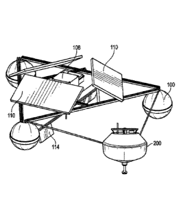
Turning now to Fig. 7, a mechanical water moving device in the form of a RFWSS
99 is shown
having three flotation spheres 100 supporting an aluminium corrosion resistant
frame, 102
which supports a platform 104 housing a motor 106, a battery pack 108 and
solar panels 110. A
shaft 112 coupled to the motor is shown having paddles 114 and 116 attached
thereto. The
paddles 114, 116 rotate with the shaft sweeping through 360 degrees within the
water. The
distance between each of the flotation spheres depends upon the overall size
of the RFWSS
device and this dimension can vary. This critical rotation speed will be
determined by the size
of the rotating blades/paddles of the RFWSS, angles of rotation, local water
temperature, water
flow rate, wind speed above the waterbody, the topography of the waterbody and
proximity to
physical barriers (e.g., other mechanical devices, islands, weirs, aquatic
plants, etc.). By way
of example, an RFWSS having 3 blades of length 1-2 m can have a rotation speed
between 5
and 200 revolutions per minute. This critical rotation speed is expected to be
below 200 rpm
and likely below 50 rpm to achieve a Reynolds Number of the radially outward
flowing water
below 5,000, and preferably below 1000. Preferably the rotation speed is
between 5 and 15
RPMs. In a preferred embodiment the RFWSS and the AMFGD together use less than
100 watts
of power.
Figs. 8 through 10 are shown having solar panels installed which power the
electric motor of
the RFWSS. Deep cycle batteries are provided so that the RFWSS can operate at
night.
In a preferred embodiment shown in FIG. lithe RFWSS 99 and the transducer 200
are tethered
by a tether together so that one can influence and enhance the performance of
the other. It is
preferred that the RFWSS be disposed within a distance from the transducer at
which the
transducer-based device 200 can provide an effective result.
Fig. 12 is a drawing showing the system wherein a RFWSS and electronic device
200 are
integrated within a single unit. An advantage of this is that the two devices
can operate at the
26
Date recue/Date received 2024-01-30
Doc. No. 318-23 CA
Greentech
same time powered from the same solar powered battery and the electronic
device can operate
or mildly churned water as a result of the action of the RFWSS 99. The
effective operating range
of the RFWSS is approximately 70 meters although not limited thereto and
depends on the size
of the RFWSS. This range is less than the effective operating range of the
electronic device such
as the one described heretofore. The property changes in the water columns
within the operating
range of the RFWSS will cause convective mixing with the adjacent water
columns.
Consequently, to maximize the acceleration of oxygenation of a large
waterbody, placing evenly
4 RFWSSs 100m from each electronic device will likely be the most cost-
effective arrangement.
For smaller waterbodies, e.g., those with radius of 100 m or less, the device
described is believed
to be adequate.
As has been described within this disclosure, the use of the AMFGD and RFWSS
together,
provide advantages over the sum of their benefits alone. Numerous aspects of
synergy result
from their use together. There is a greater gas exchange rate by their use
together than the sum
of their outputs alone, and less power is required when they are used together
as the viscosity
and surface tension are lessened, thereby reducing the energy required to turn
the paddles of the
RFWSS. In addition to this, the otherwise resulting anoxic state of the water
at night, is lessened
by using the RFWSS with the AMFGD. The low power RFWSS when in operation
continually
moves the water from lower depths into an upper region where the AMFGD is able
to affect
this water so that accelerated gas exchange can occur. We know of no other two
devices that
when used together that can achieve as much gas exchange, i.e. oxygenation of
large water
bodies as the AMFGD with the RFWSS with as little power consumed.
27
Date recue/Date received 2024-01-30