Note: Descriptions are shown in the official language in which they were submitted.
WO 2022/180353
PCT/GB2022/050239
AN APPARATUS FOR MAINTAINING A PLANT
This invention relates to an apparatus for maintaining a plant, a method for
maintaining a
plant and a kit of parts for the same.
BACKGROUND
Fruit-bearing or flowering plants require light and nutrients to grow, and by
controlling the
levels of light and nutrient provided the plant, it is possible to enhance or
impede plant
growth. Peppers, tomatoes, and strawberries are examples of popular home-grown
fruit-
bearing plants.
Plant growth may be improved using reservoir growing techniques, such as deep
water
culture (DWC) hydroponics. In DWC hydroponics the roots of the plant are
submerged in a
liquid growth medium which typically includes water and nutrients to encourage
plant
growth. As the plant grows, undesirable products, such as mineral salts, can
build up on
the inner walls of the reservoir which can undesirably impede plant growth. It
is therefore
necessary to periodically clean the reservoir to avoid this problem. It is
also necessary to
maintain the roots of the plant which requires raising the roots of the plant
from the reservoir
which risks damaging the plant and/or root base, which would negatively impact
plant
growth.
Plant growth may also be improved by using a screen for training the plant to
grow in a
particular manner. Such a screen is typically arranged above the plant and is
designed
impede vertical growth of the plant in a controlled manner. Impeding the
vertical growth of
the plant causes the plant to grow horizontally which increases the exposure
all parts of the
shoot of the plant to light, increasing the yield of flowering or fruit
bearing plants. However,
screens are often placed close to the ground, which forces the grower to
endure highly
uncomfortable positions for prolonged periods of time while maintaining the
plant.
Furthermore, training such plants with a screen can often result in the plant
becoming
entangled with the screen as it becomes dependent on the screen for structural
stability.
This is problematic, as an entangled plant is difficult to separate the screen
from the plant
without damaging the plant. This means that plants that may benefit from
reservoir growing
techniques are not compatible with training screens, as the shoots of a plant
that has
become entangled with the training screen is at particular risk of becoming
damaging when
extracting the root base from the reservoir.
CA 03209440 2023- 8- 23
WO 2022/180353
PCT/GB2022/050239
2
The present invention seeks to address at least some of these problems.
BRIEF SUMMARY OF THE DISCLOSURE
According to a first example there is provided an apparatus for maintaining a
plant, the
apparatus comprising a screen configured to train the growth of a plant
engaged therewith;
a support for holding the plant beneath the screen such that, in use, the
plant engages the
screen and a root base of the plant is disposed beneath the support, and a
lifting
mechanism operatively connected to the support and the screen and configured
to lift the
screen and the support from a first position to a second position so as to at
least partially
extract the root base from an external reservoir arranged to receive the root
base, wherein
the screen and the support are held at a pre-determined distance when moving
from the
first position to the second position.
This advantageously provides a device that overcomes the incompatibility of
training
screens and reservoir growing techniques by maintaining a pre-determined
distance
between the root base and the training screen as the support and the screen
are lifted to
extract the plant root base from the reservoir. The present device is
therefore able to raise
the root base from within an external reservoir whilst minimising the risk of
damage to the
plants engaged with the screen, thus utilising the respective advantages of
growing
techniques that use training screens and reservoir growing techniques to
provide enhanced
plant growth compared to these techniques in isolation. Further advantages of
the present
device include maximizing the light footprint of the plant, increasing the
yield per unit area
of the plant and reducing the number of plants to maintain while achieving an
increased
yield. Where the seeds of the plant or the nutrients are more expensive, this
can
considerably reduce the cost of producing the flowers or fruit from a plant.
The reservoir,
and any equipment therein, can also be cleaned and maintained in the
conventional
manner, and the root base can be accessed for maintenance when the plant is
raised using
convention techniques. There is the additional advantage that the plant can be
lifted to a
height which makes root maintenance, canopy defoliation and tucking and
training, and any
other plant maintenance possible at an ergonomic height.
CA 03209440 2023- 8- 23
WO 2022/180353
PCT/GB2022/050239
3
The lifting mechanism may comprise a pulley system. The screen and support may
be
suspended from the pulley system. The pulley system may comprise a plurality
of ropes or
cables connected to the screen and the support.
The lifting mechanism may be manually operated by the user. This is
advantageous as the
device can be operated without powered lifting equipment, and therefore can be
installed
in a wide range of indoor or outdoor locations.
The support may comprise one or more apertures for egress of the root base
therethrough.
This advantageously reduces the risk of the root base growing around a closed
container
in a constricted pattern and becoming rootbound. The apertures allow the roots
of the root
base to be air pruned in the absence of high humidity when lifted from the
reservoir, which
causes the plant to constantly produce new and healthy branching roots,
further
encouraging plant growth. The support may comprise an aerated pot or and
aerated fabric
smart pot. The support may have a side wall including one or more apertures
for the roots
to extend through. The support may be arranged to hold a porous medium, or
substrate for
supporting the root base.
The external reservoir may be part of a hydroponics system. The hydroponics
system may
be a deep water culture hydroponics system.
The support may be suspended below the screen. This provides a simple way to
maintain
the pre-determined distance between the screen and the support. The support
may be
suspended using cables. In some cases the support is held at the pre-
determined distance
from the screen by one or more rigid support structures. In some cases the
support and the
screen are secured to the lifting mechanism. In some cases, the lifting
mechanism is
connected to only one of the support or the screen. In some cases the lifting
mechanism is
arranged to maintain a pre-determined distance between the screen and the
support.
The support may be suspended above a ground-surface. This is advantageous as
the
plants can be grown with air pruning techniques. A further advantage is that
water can drain
freely from below the support to prevent water-logging. In some cases, the
support is
permanently suspended from the ground, providing airflow to a bottom surface
of the
support.
CA 03209440 2023- 8- 23
WO 2022/180353
PCT/GB2022/050239
4
The support may be connected to the screen by an adjustable connector arranged
to
maintain a user-defined distance between the screen and the support. This is
advantageous as the user-defined distance between the screen and the support
can be
adjusted to accommodate plant growth or different plants, for example once a
plant is to be
harvested and separated from the root base, the existing support can be
secured to a new
screen ready for a new plant while the harvested plant dries on the original
screen.
The screen may comprise a tubular frame. This advantageously provides a
lightweight
structure. The tubular frame may have a circular cross-section or a square
cross-section.
A square cross-section is particularly advantageous as it provides greater
resistance to
buckling compared to a tubular frame having a circular cross-section.
The screen may comprise a plurality of inter-engaging elements. The inter-
engaging
elements are preferably tensile elements, such as cord or rope. The screen may
comprise
a net, or a mesh, or similar structure.
The distance between the first position and the second position may be between
1 m and
3 m.
The screen configured to train the growth of a plant engaged therewith may be
a first
screen. The apparatus may further comprise a second screen secured above the
first
screen. The upper second screen may be configured to support, in use, a part
of the plant
extending from the first screen to the second screen. The lifting mechanism
may be
operatively connected to the second screen such that the first screen and the
second
screen are held at a second pre-determined distance when moving from the first
position
to the second position. Providing an upper screen is advantageous for
providing support to
upper parts of the plant. For example, this may be beneficial to support fruit-
bearing plants.
The apparatus may comprise a container for containing the root base. The
support may be
configured to provide an air-tight seal with the support. When secured to the
support, the
container and support may be arranged to provide a cavity for containing the
root base. The
container may be hermetically sealed to maintain a pre-determined growing
condition within
the cavity. The growing condition may be a level of humidity. This is
advantageous as the
container is able to keep the root base in a humid environment when the plant
is raised for
prolonged periods, for example during plant and/or reservoir maintenance.
CA 03209440 2023- 8- 23
WO 2022/180353
PCT/GB2022/050239
According to a second example there is provided a grow tent comprising the
aforementioned apparatus. The grow tent advantageously provides a sealable
covering
within which the present device can be assembled and operated. Additional
apparatus for
5 controlling growing conditions, such as lighting, temperature, humidity
and nutrient levels
may also be installed within the grow tent to provide optimum growth
conditions for the
plants contained therein.
According to a third example there is provided a method of maintaining a
plant, the method
comprising providing the aforementioned apparatus, providing a reservoir for
receiving a
root base of a plant, introducing a growth medium into the reservoir, securing
the plant to
the support such that the plant engages the screen and the root base of the
plant is at least
partially submerged within the growth medium, operating the lifting mechanism
to raise the
support and screen such that the root base is raised above the growth medium
disposed
within the reservoir while a pre-determined distance between the screen and
the support is
maintained. A majority of the root base may be submerged within the growth
medium in the
first position.
According to a fourth example there is provided a kit of parts comprising a
screen, a support
and a lifting mechanism configured to operate as an apparatus according to the
aforementioned apparatus. This advantageously provides a modular system from
which the
present device can be assembled.
According to a fifth example there is provided a support rig comprising the
aforementioned
apparatus. The support rig comprises a shelf for supporting the external
reservoir below the
screen, and wheels for providing manoeuvrability to the support rig.
BREIF DESCRIPTION OF THE DRAWINGS
The apparatus for maintaining a plant will now be described by way of example
only with
reference to the accompanying drawings in which:
Figure 1 is a schematic of the apparatus, wherein the screen and support are
arranged in a first position;
CA 03209440 2023- 8- 23
WO 2022/180353
PCT/GB2022/050239
6
Figure 2 is a schematic of the apparatus, wherein the screen and support are
arranged in a second position;
Figure 3 is a schematic of the screen of the apparatus;
Figure 4 shows the support and reservoir of the apparatus;
Figure 5 shows the lower pulley part of the lifting mechanism of the
apparatus;
io Figure 6 shows the upper pulley part of the lifting mechanism
of the apparatus;
Figure 7 shows the figure-of-eight device of the lifting mechanism of the
apparatus;
Figures 8A & 8B show the support connectors of the lifting mechanism of the
apparatus;
Figure 9 shows the three-way swivels of the lifting mechanism of the
apparatus;
Figure 10 shows another example of the apparatus with two screens;
Figure 11 shows connectors for connecting the two screens together;
Figure 12 shows an aerated pot used in place of the support and reservoir in
the
apparatus;
Figure 13 shows the aerated pot of Figure 9 suspended beneath the screen;
Figure 14 shows a grow bag used in place of the support and reservoir in the
apparatus, suspended below the screen; and
Figure 15 shows a schematic of the apparatus located in a mobile support rig.
DETAILED DESCRIPTION
CA 03209440 2023- 8- 23
WO 2022/180353
PCT/GB2022/050239
7
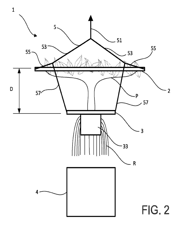
Referring now to Figures 1 and 2, there is shown an apparatus 1 for
maintaining a plant P.
The apparatus 1 comprises a screen 2 for training the growth of plant P when
engaged with
the screen 2, and a support 3 for holding the plant P beneath the screen 2. In
use, the plant
P engages the screen 3 which allows a grower to train the plant P grow
horizontally by
topping the plant, or breaking down the main shoot of the plant, and using a
series of Low-
Stress-Training (LST) techniques to grow the plant P below the screen 2, until
shortly into
the flowering period. As shown in Figure 4, the support 3 includes a
receptacle 33 for
holding a porous medium, or substrate, for example clay pebbles, coco coir or
perlite. The
receptacle 33 has walls, each of which has a number of apertures which allow
the root base
R to grow out of the apertures of the receptacle 33, resulting in air pruning
of the roots. As
illustrated in Figure 1, the shoot of the plant P extends towards the screen 2
and engage
the screen 2 in a vertical direction.
Referring now to Figure 3, there is shown a schematic of the screen 2 in plan.
The screen
2 is made from tubular frame 21 and a net of pre-weaved elasticated nylon cord
23. In this
example, the tubular frame 21 is constructed using four pieces of aluminium
tubing which
are interconnected by polyvinyl chloride (PVC) elbows. In this example the
aluminium
tubing of the tubular frame 21 has a circular cross-section and the elbows are
polyvinyl
chloride (PVC) elbows secured to the tubular frame 21 using aluminium tape.
Alternatively,
the tubular frame may be constructed using aluminium tubing having a square
cross-
section, as shown in the example of Figures 10 and 11, secured by elbow
connectors. In
some cases, the tension in the cord 23 that is needed to engage certain plants
to act as a
training screen is sufficiently high that there is a risk of buckling when
using circular tubular
frame. In this case, a screen made of square tubular frame is able to provides
greater
buckling resistance when the cord 23 is under high tension. A further
advantage of a square
tubular frame is that adhesive or tape is not necessary to secure the tubular
frame 21 to the
elbow connectors. The net is secured to the tubular frame 21 using a plurality
of hook and
loop straps. The spacing between the individual sections of cord 23 is
approximately 100
mm, but it would be apparent this was merely exemplary and that other spacing
would be
suitable depending on the specific application. For example, the spacing may
be between
50mm and 150mm, or between 80mm and 120mm. Similarly, while nylon cord 23 is
described, it would be apparent that cord made of other materials may be used
with the
present device. Similarly, while a cord is used to form a series of inter-
engaging elements,
other structures may be used to engage the plant as required.
CA 03209440 2023- 8- 23
WO 2022/180353
PCT/GB2022/050239
8
The apparatus 1 has a reservoir 4 which contains a growth medium of water (not
shown)
and appropriate nutrients to promote healthy plant growth. The reservoir 4 is
a part of a
deep water culture (DWC) hydroponics system and so contains DWC equipment (not
shown) such as a pump for replacing water and replenishing nutrients into the
reservoir 4.
While a DWC hydroponics system is described, it would be apparent that this
was merely
one type of hydroponics system suitable for use with the present apparatus 1,
and that
other hydroponics systems may be used. Similarly, a hydroponics system is
merely one
examples of a suitable reservoir growing technique suitable for use with the
present
apparatus 1, and other reservoir growing techniques would be suitable with the
present
io apparatus 1. The support 3 is releasably secured to the reservoir 4 so
that the root base R
can be easily raised from the reservoir 4. The support 3 is also secured to
the reservoir 4
in a manner which provides an air-tight seal between the support 3 and the
reservoir 4.
While a circular support 3 and a circular reservoir 4 are shown, it would be
apparent that
this was merely exemplary and that other configurations of support 3 and
reservoir 4 would
be able to form an air-tight seal. Similarly, a sealing element, such as a
gasket or 0-ring or
other resiliently deformable element, may be provided to provide the seal
between the
reservoir 4 and the support 3. When the support 3 is secured to the reservoir
as shown in
Figure 1, at least part of the root base R is submerged in the water in the
reservoir 4.
During use, debris such as mineral salts may accumulate on the inner surfaces
of the
reservoir 4, as well as on any equipment inside of the reservoir 4. In order
to remove the
debris, the support 3 and plant P are raised to a second, raised, position
shown in Figure
2. The apparatus 1 comprises a lifting mechanism 5 which is operatively
connected to the
support 3 and the screen 2. The lifting mechanism 5 is configured to lift the
screen 2 and
the support 3 from a first position where the root base R is disposed within
the reservoir 4,
to a second position where the root base R is raised from the reservoir 4. In
the raised
position, a user can access the inside of the reservoir 4 because the support
3 is spaced
from the reservoir 4, along with the attached receptacle 33 and root base R.
The screen 2
and support 3 are arranged to maintain a pre-determined distance D when moving
from the
first position to the second position so as to minimise damage to the plant or
root base when
lifting the root base to the raised position. As shown in the Figures, this
can be achieved by
suspending the support 3 below the screen 2. However, it would be apparent
this was not
essential, and the support 3 may be held below the screen 2 at a pre-
determined distance
without suspending the support 3 using cables. The distance between the first
and second
CA 03209440 2023- 8- 23
WO 2022/180353
PCT/GB2022/050239
9
positions is controlled based upon the requirements of the user, but is
typically between 1
m and 3 m.
The lifting mechanism 5 comprises two pulley systems 51 which may be manually
operated
by a user. A pulley system 51 is located on each of two opposing sides of the
screen 2 (see
Figure 11). The illustrated apparatus 1 utilises a double block-and-tackle
pulley system,
comprising four 6mm double pulley blocks 51a, 51b. Cables 53 connect each
pulley system
51 to respective corners of the screen 2. Thus, the four corners of the
illustrated screen 2
are supported by four cables 53 that extend from the two pulley systems 51.
Each cable 53
is connected to the screen 2 by a carabiner 55 secured to the screen 2. While
a carabiner
55 is described, it would be apparent other fixing means would be suitable for
connecting
the cable 53 to the screen 2.
The support 3 is suspended under the screen 2 by cables and an adjustable
connector 57.
The adjustable connectors 57 between the screen 2 and the support 3 allow the
distance
between the screen 2 and the support 3 to be adjusted as required. For
example, different
plants may grow to different heights before becoming fruit-bearing or
flowering, and
therefore it is advantageous to be able to adjust the connector 57 to
accommodate plant
growth. Similarly, when a plant P is ready for harvesting, the shoot attached
to the screen
may be separated from the root base R, and the support 3 may be simply
attached to a
new screen to start growth of a new plant. Thus, a wide variety of plants can
be
accommodated for with the adjustable connector 57. A turnbuckle is shown as
the
adjustable connector 57 in Figure 8A, and a rope ratchet is shown as the
adjustable
connector 57 in Figure 8B. Using a rope ratchet provides a greater range of
adjustability of
the distance between the screen 2 and the support 3 compared to the
turnbuckle. Rope
ratchets are also easier to adjust, and have a lower mass, further aiding the
manual lifting
of the screen and support. It would be apparent these were merely two examples
of
adjustable means to vary the distance between the support 3 and the screen 2.
The
adjustable connector 57 provides approximately 75 mm of adjustability, in
order to maintain
a user-defined distance D between the screen 2 and the support 3. However, it
would be
apparent this was merely exemplary and that suitable adjustable connectors may
be used
to provide the required pre-determined distance and adjustability between the
screen 2 and
the support 3. The rope ratchet advantageously allows the user to select any
distance D
between the screen 2 and support 3. While the adjustable connector 57 is
operated
manually by a user, it would be apparent the apparatus 1 could include a
controller
CA 03209440 2023- 8- 23
WO 2022/180353
PCT/GB2022/050239
operatively connected to the adjustable connector 57 using a wired or wireless
connection,
and configured to actuate a motor to adjust the adjustable connector 57. This
would be
particularly advantageous where multiple apparatus 1 were set up to grow a
large number
of plants in parallel.
5
Referring now to Figures 5-9, there is a double pulley 51aat the upper end and
lower end
of each pulley system 51. Each pulley system 51 also has a polypropylene rope
extending
between the upper 51b and lower 51a pulleys. However, it would be apparent
that rope
10 made of other materials would be suitable. It would also be
apparent that a rope is only one
example of a suitable tensile element suitable for operating the pulley system
51. Each
upper pulley 51b is suspended from above, in this example via a carabiner. One
end of the
rope is tied to the respective upper pulley 51b. The end of each rope extends
from their
respective upper pulley 51b and are releasably secured by winding the ropes
around a
waist of a figure-of-eight device 52. VVhen tension is applied to the end of
one of the ropes,
the respective lower pulley 51a moves upwards towards the upper pulley 51b. By
pulling
both ropes simultaneously, both lower pulleys 51a can be raised at the same
time to raise
the screen 2 and support 3 in a level manner without damaging the plant.
Cables 53 are connected to each lower pulley 51a at one end, and to a three-
way swivel
59 at the other end. Each three-way swivel 59 is connected to one of the
carabiners 55
connected to the screen and one of the adjustable connectors 57 suspending the
support
3. The connection between each three-way swivel 59 and each cable 53,
carabiner 55 and
adjustable connector 57 is independently pivotable. Each carabiner 55 is
fastened to the
tubular frame 21 of the screen 2 via a stainless steel eyelet screwed into a
respective PVC
elbow of the tubular frame 21. Each eyelet is connected to the respective
three-way swivel
59 by the carabiner 55. The three-way swivels 59 avoid undesirable torsional
loads
accumulating in any of the cables 53, carabiners 55, or adjustable connectors
57. It will be
appreciated that cables, carabiners and adjustable connectors are merely
exemplary and
other connectors would be suitable for use with the present apparatus 1.
The cables are preferably 3 mm PVC coated, stainless steel wire rope. Loops
are provided
in the ends of the cables using 3 mm zinc-plated duplex steel wire rope grips.
CA 03209440 2023- 8- 23
WO 2022/180353
PCT/GB2022/050239
11
In order to clean or maintain the inside of the reservoir 4, and any equipment
therein, the
screen 2, support 3 and plant P are lifted to the second position. This is
achieved by using
the figure-of-eight device 59 to pull the ropes downwards to lift the screen
2, support 3 and
plant P. Once the support 3 and screen 2 are raised to the second position,
the figure-of-
eight device 59 is used to secure the ropes to maintain an equilibrium in the
tension of the
two ropes to hold the screen 2, support 3 and plant P at the desired height.
It will be
appreciated that the figure-of-eight device 59 may be replaced by any suitable
releasable
locking mechanism to achieve the described function. It would also be
appreciated that the
lifting mechanism may utilise a powered device, such as a winch for lifting
and holding the
io support 3 and screen 2 in the raised position for maintaining the
reservoir 4 and/or the plant
shoot or root base R. The lifting mechanism may also include one or more
pneumatic or
hydraulic lifting mechanisms. This would be particularly advantageous where
multiple
apparatus 1 are installed in parallel and a number of screens 2 need to be
lifted together.
Alternately, the figure-of-eight device 59 may be omitted completely, and the
ropes secured
by tying to a fixed object.
Once in the second position the reservoir 4, and any equipment therein, can be
removed
for cleaning and maintenance, or cleaned and maintained in-situ. Any cleaning
and
maintenance to the root base R may also be performed while the root base R is
raised. The
root base R may also be protected, whilst in the second position, by securing
a container
(not shown) to the support 3 to contain the root base R. As the container need
not contain
any nutrients or liquid, it is much lighter than the reservoir 4, and can be
easily lifted by a
user and secured to the support 3 while the root base R is extracted from the
reservoir 4
and outside the growth medium. The container provides a hermetically sealed
cavity for
containing the root base R, which avoids unintended air pruning of the root
base R, which
can occur during the prolonged periods when the root base R may be exposed to
ambient
air while the reservoir 4 or plant canopy is being maintained. While a
hermetic seal is
desirable, it would be apparent this was not essential. It would also be
apparent that the
container may include one or more devices for maintaining one or more
environmental
conditions within the cavity the container. This is particularly useful if the
root base will be
raised for a prolonged period of time.
The second position is also suitable for maintenance of the shoot of the plant
P, such as by
pruning. This is beneficial if, in the second position, the shoot is at a more
ergonomic height
than in the first position.
CA 03209440 2023- 8- 23
WO 2022/180353
PCT/GB2022/050239
12
Once cleaning and maintenance are complete, the reservoir 4 and equipment
therein is
replaced, the figure-of-eight device 59 is disengaged from the ropes and the
screen 2,
support 3 and plant P are lowered to the first position, where the root base R
is returned to
the growth medium within the reservoir 4.
If harvesting of the plant P requires the removal of the root base and drying
of the shoot,
then the screen 2, support 3 and plant P are raised to the second position, as
described
above. When in the second position, the root base R is cut from the plant P,
and the support
3 and root base R are removed from the apparatus 1 by disconnecting the
carabiners 55
from the three-way swivels 59. The screen 2 and plant P engaged therewith can
then be
inverted to more effectively dry the plant P. Inversion of the screen 2 is
possible due to the
lower pulley 51a having a pivotable connection with the connector cables 53.
In some cases, the apparatus 1 is provided as part of a grow tent or
greenhouse (as shown
in Figures 4 to 12). In this case the upper pulleys 51b are connected to a
frame of the grow
tent or greenhouse. The screen 2 is sized so that it can still move between
the first and
second positions within the grow tent or greenhouse. The grow tent or
greenhouse may
contain other equipment to enhance growing of the plant P, such as one or more
heaters,
lights, fans and/or humidity control devices. The grow tent preferably
includes a covering
61 made from a material which enhances the growing conditions. Such materials
are known
in the art and will not be repeated here, but may comprise a thermally
insulating material.
Referring now to Figures 10 and 11, another example of the apparatus 1 is
shown. In this
example the apparatus 1 comprises two screens, a lower screen 201 and an upper
screen
203. The lower screen 203 acts as a training screen, as described above. The
upper screen
201 provides support to upper sections of a maturing plant that have grown
through the
openings in the lower screen 201. Each screen 201, 203 is preferably arranged
in the same
manner as screen 2 of the previous example, but it would be apparent this was
not
essential. The modular nature of the apparatus advantageously allows further
screens to
be added at any stage of the plant's growth in a convenient manner. In this
example the
aluminium tubing of the screens 201, 203 has a square cross-section, but a
circular cross-
section could be used.
CA 03209440 2023- 8- 23
WO 2022/180353
PCT/GB2022/050239
13
The upper screen 203 and lower screen are connected to respective cables 53
via a three-
way swivel 59. This allows the lower screen 201 to be suspended below the
upper screen
203. It would be apparent this was not essential, and that in some cases it
may be desirable
to suspend the lower screen 201 directly from the upper screen 203. The lower
screen 201
is suspended by cables 205 connected to eyelet hooks secured to the elbows of
the lower
screen 201. The support 3 is supported with adjustable connectors 57 in the
form of rope
ratchets, but it will be appreciated that turnbuckles, or any other suitable
adjustable
connector, may be used.
As in the previous example, when tension is applied to the free ends of the
ropes of the
pulley systems 51, the lower pulleys 51a and three-way swivels 59 are pulled
upwards.
Therefore, the screens 201, 203, which are connected to the three-way swivels
59, and the
support 3 are all pulled upwards together. This means that the screens 201,
203 and the
support 3 can be moved substantially synchronously between a first and second
position
with minimal risk of damage to the plant, as the pre-determined distance
between the
screens 201, 203 is maintained while the distance between the support 3 and
the lower
screen 203 is maintained. It would be apparent that the pre-determined
distance between
the support 3 and the lower screen 201 may be different to the distance
between the upper
screen 203 and lower screen 201.
Referring now to Figure 12 and 13, another example of the apparatus is shown.
In this
example the support is an aerated pot 6. The aerated pot 6 is a cylindrical
container with
an open top and walls which have a series of holes through which the roots of
the plant
can grow, and eventually be air pruned. The aerated pot 6 contains a mixture
of soil and
porous medium and the root base R of the plant P. The porous medium may be,
for example
clay pebbles, coco coir or perlite. In this example, the reservoir 4 is
omitted.
The adjustable connectors 57 are connected to sidewalls of the aerated pot 6.
The screen
2 and aerated pot 6 can be lifted to the second position in the same manner as
described
above. This may be, for example, for cleaning or maintenance of the aerated
pot 6, or for
pruning of the plant P. As with the previous examples, the aerated pot 6 and
screen 2 are
lifted while maintaining a predetermined distance D therebetween. Furthermore,
when
using an aerated pot 6, it is possible to permanently suspend the aerated pot
6 from the
ground, which allows air circulation to the bottom of the pot 6. This also
aids in water
CA 03209440 2023- 8- 23
WO 2022/180353
PCT/GB2022/050239
14
draining from the aerated pot 6. The aerated pot 6 and the screen 2 are shown
in the second
position in Figure 10.
Referring now to Figure 14, another example of the apparatus is shown. In this
example
the support comprises a felt aerated fabric smart pot 7. The smart pot 7
contains a mixture
of soil and a porous medium and the root base R of the plant P. The porous
medium may
be, for example clay pebbles, coco coir or perlite. The reservoir 4 is omitted
in this example.
The adjustable connectors 57 are fastened to the smart pot 7 via eyelets
formed in the
smart pot 7. The screen 2 and the smart pot 7 can be lifted to the second
position in the
same manner as described above. This may be, for example, for cleaning or
maintenance
of the smart pot 7, or for pruning of the plant P. As with the previous
examples, the smart
pot 7 and screen 2 are lifted while maintaining a predetermined distance D
therebetween.
Furthermore, when using a smart pot 7, it is possible to permanently suspend
the smart pot
7 from the ground, which allows air circulation to the bottom of the pot 7.
This also aids in
water draining from the smart pot 7. The smart pot 7 and screen 2 are shown in
the second
position in Figure 11.
Whilst the examples of Figures 12-14 are shown with a single screen 2, the
aerated pot 6
or smart pot 7 could be used in the apparatus of the example shown in Figures
10 & 11,
which uses two screens 201, 203. Also, the adjustable connectors 57 of these
examples
are shown as turnbuckles, but rope ratchets, or any other suitable adjustable
connector,
may be used instead.
Referring now to Figure 15 there is shown an example where the apparatus 1 is
provided
in a mobile support rig 8. The apparatus 1 may be that of any of the previous
examples.
The support rig 8 has a frame 81 formed of frame members 81a, 81b, 81c
connected to
one another. In this example the frame members 81a, 81b are 25 mm square metal
(e.g.
aluminium or mild steel) box section. The frame members 81c, in this example,
are 25 mm
square metal (e.g. aluminium or mild steel) box section having lips (not
shown) to support
a shelf 82 located at the bottom of the support rig 8. Whilst the frame
members 81a, 81b,
81c of this example are made of metal, it will be appreciated that any
suitable material could
be used. The shelf 82 supports the reservoir 4, aerated pot 6 or smart pot 7.
In this example
the shelf 82 is a polyvinyl chloride (PVC) coated rigid steel mesh, although
any shelf 82
which supports the reservoir 4, aerated pot 6 or smart pot 7 can be used.
Wheels, or
CA 03209440 2023- 8- 23
WO 2022/180353
PCT/GB2022/050239
casters, which may be lockable, are attached to the bottom of the support rig
8 In this
example, the wheels are connected to three-way connectors that connect frame
members
81c and 81a, for providing manoeuvrability to the support rig 8. While four
wheels are
shown attached to the support rig 8 it would be apparent that more or fewer
wheels may be
5 added depending on the specific requirements of the support rig 8. While
a cuboid frame
81 has been illustrated, it would be apparent that this was merely exemplary
and that other
shapes of frame 81 are suitable for use with the present apparatus 1.
The upper pulleys 51b of the lifting mechanism 5 are connected to upper frame
members
10 81a. The screen 2 is sized so that it can move between the first and
second positions within
the support rig 8 to operate the apparatus 1 as described previously. The
support rig 8 may
contain other equipment to enhance growing of the plant P, such as one or more
heaters,
lights or fans.
15 Any of the examples described herein may have a light source (not shown)
configured to
illuminate the plant. The light source may be light emitting diode (LED) strip
lighting. The
strip lighting may be mounted to one of the screens 2, 201, 203. More
specifically, strip
lighting may be mounted to the lower side of the upper screen 203, such that
the parts of
the plant between the two screens 201, 203 are illuminated. The strip lighting
may be
mounted to the frame of the grow tent, greenhouse or support rig 8. Strip
lighting may be
attached via any suitable fastener, such as screws, rivets, ties, adhesive.
Strip lighting
advantageously allows the plant to be illuminated from multiple directions, to
improve light
exposure to all parts of the plant, thus further enhancing plant growth.
It would be apparent that while a single apparatus 1 has been described, an
arrangement
of multiple of such apparatus 1 could be operated to grow one or more plants.
This would
enable enhanced plant growth on a commercial scale, as well as on a domestic
scale.
It will be appreciated by those skilled in the art that several variations to
the aforementioned
embodiments are envisaged without departing from the scope of the invention.
For
example, the screen may be of a suitable size for a plurality of plants to
engage therewith.
Each plant may be held by a respective support, which is connected to a common
lifting
mechanism for the screen and the other supports for plants engaged with the
same screen.
Alternatively, a common support may be provided for all of the plants engaged
with the
same screen. The reservoirs may be interconnected in a flow system, whereby
nutrients
CA 03209440 2023- 8- 23
WO 2022/180353
PCT/GB2022/050239
16
and water are circulated. Otherwise there may be a common reservoir for the
plurality of
plants.
It will also be appreciated by those skilled in the art that any number of
combinations of the
aforementioned features and/or those shown in the appended drawings provide
clear
advantages over the prior art and are therefore within the scope of the
invention described
herein.
CA 03209440 2023- 8- 23