Note: Descriptions are shown in the official language in which they were submitted.
WO 2022/172257
PCT/IB2022/051345
1
Description
Title of Invention: A Novel Foam Article
Background Art
[00011 Foam is widely used in many applications such as impact
protection, comfort,
thermal insulation, acoustic insulation, floatation, and construction. The
foam article
manufacturing has been mostly focused on making foams that have a single
density
and, in many cases, foams are not sufficiently optimized for specific
applications. This
results in making foams that are relatively heavy and are not optimized in
terms of
strength, density, durability, insulation, and shock-absorbing capability for
a given ap-
plication.
[0002] Customizing a foam article by just uniformly varying the
density and porosity in a
micro-level does not necessarily provide the best result for a given
application. For
instance, Expanded Polystyrene (EPS) beads after curing and ageing are about
95% air
and only 5% plastic. However, an EPS foam made from the beads may not be in
its full
capacity of strength, shock-absorbing ability, floatation, durability and
insulation for
the volume it occupies. With vast applications for foam articles, enhancing
the foam
characteristic and reducing its weight is desirable in many applications.
[0003] In almost all applications of foam articles, maximum
performance and minimum
weight are desirable and using single-density foams in their available forms
may not
yield the best results. In applications such as thermal and acoustic
insulation (in
machines, appliances, and construction), shock-absorption (in head protection,
body
protection, and vehicles), and transportation (in vehicles, and vessels) a
single-density
foam is mainly used. In some designs, layers of foams with different densities
are used
to improve the shock-absorption capability of a foam article. Multi-density
foams can
perform better than single-density foams, but they can be costly and have
limitations in
design. Floating applications such as boats, buoys, and surfboards also mainly
use
foam articles with single density.
[0004] A foam's mechanical properties can vary depending on the
production procedure and
the type of polymer used. In general, foams can be divided into two
categories, single-
impact, and multiple-impact foams. The single impact foams such as EPS and EPA
(Expanded Polylactic Acid) after deformation by an impact they do not go back
to their
original foim and their structures will be peimanently compromised. On the
other
hand, multiple-impact foams such as those made from polypropylene or
polyethylene
can return to their initial form after being deformed. Due to the high volume
of foam
used in various applications, any improvement to enhance the foam
characteristic and
reduce the amount of foam used for a given application is attractive to the
industry.
CA 03207743 2023- 8-8
WO 2022/172257 PCT/1B2022/051345
2
Summary of Invention
[0005] This summary is provided to introduce a variety of concepts
in a simplified form that
are further described below in the Detailed Description. This summary is not
intended
to explain important features of the claimed subject matter, nor is it
intended to be used
as a tool in determining the scope of the claimed subject matter. In an
aspect, the
present disclosure describes a novel foam article, and the method of making
such foam
articles.
[0006] Foams are mainly comprising very small cavities (micro-
porosities or micro-cavities)
that in most cases arc uniformly distributed throughout their structure.
[0007] The presented invention resulted from observing and
mimicking nature. Particularly,
the invented design is inspired by the bone structure. Bones may look solid to
the
naked eye, yet they comprise micro-cavities as well as macro-cavities. The
macro-
cavities in the bone structure are usually in the form of hollow space in the
middle of
the bone. This allows the bone to have an optimum structure by harvesting the
benefits
of both micro and macro cavities. By mimicking bone structure, this invention
describes a foam article structure with both micro-cavities and macro-
cavities. The
invention also describes methods of moulding foam articles to enhance the foam
article
performance for a given application by creating and engineering larger
cavities
(macro-cavities) in any given foam articles. The invention also allows a more
sus-
tainable usage of foam by reducing the amount of expanded polymer beads used
for
the foam article.
[0008] According to a first aspect of the invention, there is
provided a method of manu-
facturing a foam article by providing a cavity-defining structure into a mould
when
moulding expanded polymer beads to create macro-cavities in the foam article.
[0009] The cavity-defining structure may comprise objects with open
cavities, objects with
closed cavities, sheets, covering layers, meshed layers, object with
perforations, hollow
bodies, solid bodies, or a combination thereof.
[0010] The moulding process may be done in two or more phases using
covering layers as
the cavity-defining structure in the foam article.
[0011] The moulding process may be done in one phase when objects
with open cavities,
object with closed cavities, or hollow bodies are used as the cavity-defining
structure
in the foam article.
[0012] Moulding with the expanded polymer beads and the cavity-
defining structure may be
done in multiple moulding processes, wherein a foam article with an open-
cavity is
made in the first moulding process, and in the second moulding process, the
foam
article with an open cavity is covered partially or entirely by the cavity-
defining
structure, and then the expanded polymer beads are introduced to the mould to
create
CA 03207743 2023- 8-8
WO 2022/172257 PCT/1B2022/051345
3
the intended cavity in the foam article.
[0013] Moulding with the expanded polymer beads and the cavity-
defining structure may be
done in a single moulding process, wherein the cavity-defining structure is
placed
inside a mould prior to introducing the expanded polymer beads into the mould
to
create the intended cavity in the foam article based on the shape, location,
and con-
figuration of the cavity-defining structure.
[0014] According to a second aspect of the invention, there is
provided a foam article
comprising expanded polymer beads and a cavity defined by a cavity-defining
structure within the expanded polymer beads, wherein the cavity-defining
structure
comprises objects with one of: open-cavities, objects with closed cavities,
sheets,
covering layers, meshed layers, objects with perforations, hollow bodies,
solid bodies,
or a combination thereof.
[0015] Further aspects of preferred embodiments are provided in the
dependent claims.
Brief Description of Drawings
[0016] The foregoing aspects of the present disclosure will become
more readily appreciated
as the same will become better understood by reference to the following
detailed de-
scription, when taken in conjunction with the accompanying drawings, wherein:
Fig.1
[0017] [Fig.1] shows a cross-section of a mould in accordance with
an embodiment of the
disclosure including the cavity compartments of a cavity-defining structure
that is
placed inside the mould during moulding a foam article.
Fig.2
[0018] [Fig.2] shows a cross-section of a helmet in accordance with
an embodiment of the
disclosure including the shock-absorbing liner of a helmet comprising the
cavity-
defining structure.
Fig.3
[0019] [Fig.3] shows a cross-section of a portion of a helmet in
accordance with an em-
bodiment of the disclosure comprising the cavity-defining structure in the
form of a
covering layer.
Fig.4
[0020] [Fig.4] shows a cross-section of a portion of a helmet in
accordance with an em-
bodiment of the disclosure including a covering layer as the cavity-defining
structure
that also acts as the outer shell of the helmet.
Fig.5
[0021] [Fig.5] shows a cross-section of a helmet in accordance with
an embodiment of the
disclosure including a cavity-defining structure in the form of a layer
covering the
open cavities to create macro-cavities.
CA 03207743 2023- 8-8
WO 2022/172257 PCT/1B2022/051345
4
Description of Embodiments
[0022] The detailed description set out below in connection with
the included sketches,
where like numerals reference like elements, is intended as a description of
various
embodiments of the claimed subject matter and is not intended to represent the
only
embodiments. Each embodiment described for this invention is given only as an
example or illustration and should not be construed as precluding other
embodiments.
Any reference to a direction is specific only to the diagram, to further the
clarity of the
explanation, not to limit the actual use of the invention in that direction.
The intention
for the illustrated examples is not to be exhaustive or to limit the invention
to the
precise fauns shown.
[0023] In the following section, specific details are explained to
provide a thorough under-
standing of exemplary embodiments of the present invention. It will be
apparent to one
familiar with the art that the embodiments shown may be realized without
embodying
every specific detail. The embodiments of the present invention may also
employ any
combination of features described below.
[0024] The following description provides several illustrations of
a novel foam article that
comprises a cavity-defining structure that is placed inside a mould when
moulding a
foam article using expanded polymer beads.
[0025] The presented disclosure is invented by studying and
mimicking how structures are
formed in nature. Mainly, it is inspired by the bone structure. A bone may
look solid to
the naked eye, yet it comprises micro-cavities and in addition to that, the
bone can be
hollowed to have macro-cavities. This allows the bone to have an optimum
structure
by harvesting the benefits of both micro and macro cavities. By imitating the
bone
structure, the present invention describes methods of moulding foam articles
to
enhance the foam article performance for a given application by creating and
en-
gineering larger cavities (macro-cavities) in the foam.
[0026] In the context of this invention, a macro-cavity is a cavity
that can be seen by the
naked eye.
[0027] Please note that the words cavity and porosity are used
interchangeably in the present
disclosure and assumed to have the same meaning.
[0028] As described further in this section, the cavity-defining
structure allows having
cavities and hollow spaces inside a foam article. The cavity-defining
structure can be
designed based on the application the foam is intended to be used for. The
cavity-
defining structure can reduce the amount of the expanded polymer beads used in
a
foam article, enhance its shock-absorbing ability, improve its durability,
reinforce the
foam structure, improve its thermal or acoustic insulation capability, and
allow at-
tachment of other means to the foam article.
CA 03207743 2023- 8-8
WO 2022/172257 PCT/1B2022/051345
[0029] Polymeric foams are used in a variety of applications such
as shock absorption, heat
insulation, sound insulation, comfort padding, floatation, and construction.
The
porosity in the foam helps with absorbing shocks, creating insulation,
bringing
comfort, reducing the weight of the object, floatation, and filling voids.
[0030] A calculated increase in the porosity of a foam article can
significantly improve its
performance for all the applications such as better impact mitigation, better
insulation
(both thermal and acoustic), better durability, and better floatation.
[0031] One of the common materials used for making floatation
objects such as buoys is
expanded polystyrene (EPS). The buoys usually are in very rough environments
and
receive impacts from vessels, waves, and shorelines. Using cavity-defining
structure in
the foam article used in marine application reduces the amount of polymer
beads used
in the foam article, increases its buoyancy, reinforces the structure of foam
used in the
floatation objects, improves the durability of the foam, and also the cavity-
defining
structure can provide attachment means for the foam article to securely
connect that to
other objects such as a boat, boat docking, or other parts of a vessel.
[0032] Conventional moulding of foams such as Expanded Polystyrene
(EPS) and its bio-
degradable version Expanded Polylactic Acid (EPA) is mainly dependent on the
uniform micro-porosity that cured beads provide and the geometry of the foam
article,
and in most cases, no macro-porosity or macro-cavity is considered in the foam
structure. Such designs of foams in the industry results in consuming more raw
materials and manufacturing foams that are relatively heavy and their
performance for
a given application are not optimized. Although foams such as EPS and EPA are
around 95% porous (volume ratio 20 air to 1 plastic), in almost all normal
impact ap-
plications such as helmets and packaging, the foam does not compress 20 times
of its
original thickness. Having the foam compressed to two-thirds of its original
thickness
would be considered a good performance. A low compression of foam during
impact
results in transferring more of the shock to the object/person the foam was
intended to
protect. One of the reasons behind the low performance of foams is that the
beads are
placed tightly next to each other and there is no space for them to laterally
expand
when compressed vertically. Adding macro-porosity or macro-cavity to foams
improves their compressibility and as a result, they can be lighter and yet
perform
better. Macro-cavities create air gaps that help the collapse of beads during
impact and
allow the foam to reduce the impact force considerably better. Macro-air-gaps
also
improve the insulation (both acoustic and thermal applications) and
floatation. In
addition, being able to control the porosity in a foam article allows
designing the foam
to the specifications which optimize its performance for a given application.
[0033] The present disclosure, in an aspect, introduces a novel
foam article and a method of
moulding that creates foam articles with a defined cavity which can reduce the
weight,
CA 03207743 2023- 8-8
WO 2022/172257 PCT/1B2022/051345
6
reinforce the structure of the foam article and it can increase its
performance for a
given application. In an embodiment, creating the macro cavity is achieved by
placing
a structure inside the mould prior to introducing the expanded polymer beads
inside the
mould. The macro-scale cavities arc defined by the embedded cavity-defining
structure
in the mould and the structure creates cavities in the areas that are needed.
[0034] Conventional foam articles can include open-cavities.
However, open cavities have
limitations, and can only he used under certain conditions. For instance, for
packaging
using open cavities is quite common to reduce the foam used in the packaging.
The
concept is feasible as the foam is normally placed inside a box as the final
packaging
layer. Open cavities are not very practical if the open cavity will be exposed
in the
final product. In the present disclosure, the final foam has no open cavity or
no explicit
open cavities, and the cavities are mainly created inside the final foam
article by using
the cavity-defining structure. Such a concept, allows the foam to be used for
a vast
array of applications without the existing limitations.
[0035] In an embodiment, moulding with the expanded polymer beads
and the cavity-
defining structure is done in multiple moulding processes, such that a foam
article with
an open cavity is made with the expanded polymer beads in the first moulding
process.
Then, in the second moulding process, the foam article with the open-cavity is
placed
in a mould and is covered partially or entirely by the cavity-defining
structure, and
then the expanded polymer beads are introduced to the mould to create the
intended
cavity in the foam article. In this case, a layer covers the open cavity from
the first step
to define the closed cavity. The layer may be a thin film, membrane, sheet or
mesh,
and it can be conformable or rigid.
[0036] In an embodiment, moulding with the expanded polymer beads
and the cavity-
defining structure is done in multiple moulding processes, such that a foam
article
without an open cavity is made with the expanded polymer beads in the first
moulding
process. Then, in the second moulding process, the foam article without the
open-
cavity is placed in a mould and the cavity-defining structure in a form or
shape of an
object with an open-cavity is placed such that the object and the foam article
made in
the first moulding together create a closed cavity. Then, the expanded polymer
beads
are introduced to the mould to conform around the closed cavity. In this case,
a rigid
layer with an open cavity is placed in the mould in the second moulding
process to
define the closed cavity with the help of the first moulded foam article. The
layer may
be a thin sheet or mesh.
[0037] Moulded foam articles have a large variety of applications,
and can be used in
protective headgears, vehicle safety features and components, airplanes,
boats, vessels,
construction, thermal insulation, acoustic insulation, floatation devices,
comfort
paddings, and other applications. All conceivable applications of the foam
articles can
CA 03207743 2023- 8-8
WO 2022/172257 PCT/1B2022/051345
7
benefit from the addition of a cavity-defining structure and macro-cavities
introduced
in the present disclosure.
[0038] In recent years, using foams such as EPS foams in
construction has significantly
increased. EPS foam is used for insulating buildings (both thermal and
acoustic) and
filling voids when constructing bridges, roads, or buildings. By using the
cavity-
defining structure in the foam article, it is possible to reduce the amount of
foam used
in construction by 15% to 30%. At the same time, the foam will have superior
properties in terms of strength, and insulation. It is known that creating
enclosed
cavities can improve thermal resistance. Polymer beads used in EPS foams are
already
filled with microcavities and are around 95% void and only 5% plastic. Such
charac-
teristic has made EPS lightweight, great insulant, and great shock absorber.
The cavity-
defining structure offers macro-cavities in addition to the existing
microcavity in the
foam. These two types of cavities (i.e. macro and micro) are complementary and
enhance the performance of the foam for a given application.
[0039] The following detailed description comprises sketches, where
similar numerals
reference similar elements, is intended as a description of various
embodiments of the
claimed subject matter and is not intended to represent the only embodiments.
Each
embodiment defined for this invention is given only as an example or
illustration, and
should not be construed as precluding other embodiments. Any reference to a
direction
is specific only to the diagram, to further the clarity of the description,
not to limit the
actual application of the invention to that direction. The purpose of the
illustrated
examples is not to be exhaustive or to limit the invention to the precise
fatrns shown.
[0040] In the following section, specific details are explained to
provide an in-depth under-
standing of the exemplary embodiments of the present invention. It will be
apparent to
one familiar with the art that the embodiments shown may be realized without
embodying every specific detail. The embodiments of the present invention may
also
employ any combination of features described below.
[0041] The following description provides several illustrations of
the cavity-defining
structure for foam articles by means of placing the cavity-defining structures
in the
mould and the methods for making the foam article have a defined macro cavity.
[0042] The present disclosure defines a novel foam structure with a
macro-cavity and ways
for moulding foam articles comprising macro-cavity, which allows the foam to
perform better than foam articles that only comprise micro-cavities. In this
regard, the
cavity-defining structure allows the foam article to have both micro-cavities
and
macro-cavities, which results in better overall performance such as lower
weight,
better strength, better shock-absorption, better durability, and better
insulation. Such
characteristics are desirable in many applications of foam articles.
[0043] Moulding foam articles with macro-cavities results in
consuming less raw material
CA 03207743 2023- 8-8
WO 2022/172257 PCT/1B2022/051345
8
which makes the foam more cost-effective. The macro-cavities are preferably
greater
than 0.3 cm' in volume each, more preferably greater than 3 cm' depending on
the ap-
plication.
[0044] In one embodiment, a defined-cavity in macro-scale is
created by placing a cavity-
defining structure in a mould prior to filling the mould with foam ingredients
such as
expanded polymer beads or other foam ingredients in fluid or solid forms and a
com-
bination thereof.
[0045] In one embodiment, the cavity-defining structure in the
mould generates one or more
of: a cavity, hole, channel, vein, or any other hollow spaces in the foam
article, as well
as attachment means for the foam article.
[0046] In one embodiment, the cavity-defining structure creates
open or closed cavities.
[0047] In one embodiment, the moulding includes multiple moulding
phases, using the same
or different moulding tools.
[0048] In one embodiment, the cavity-defining structure is made of
one or more hollow
compartments that are attached by means of solid or hollow connectors, and the
connectors attach the hollow compartments to each other.
[0049] In one embodiment, the cavity-defining structure includes a
grid-like structure of
hollow compartments and hollow or solid connectors or layers. At certain
locations,
the cavity-defining structure can comprise attachment means that are used for
attaching
the foam article to other foam articles or objects. One example of the
embodiment is
when a grid-like structure is embedded in the foam as a cavity-defining
structure in a
way that part of the structure is protruded from the outer surface of the foam
article.
The protruded part of the cavity-defining structure can comprise an attachment
means
to securely attach the foam article to another foam article or other objects
by using me-
chanical attachment means such as screws, locking mechanisms, pins, rivets,
nails,
straps, buckles, or cords. The applications of such foam articles can be in
the in-
stallation of the insulation panels, shock-absorbing parts for vehicles, shock-
absorbing
parts of head and body protective equipment (e.g. foldable helmet), floatation
parts, or
any other conceivable applications for the foam with such features.
[0050] In one embodiment, the hollow space inside the foam article
is created by the cavity-
defining structure to enhance the foam in terms of weight, strength, shock
absorption,
thermal insulation, acoustic insulation, floatation, and a combination
thereof.
[0051] In one embodiment, the foam article comprises macro-cavities
and micro-cavities.
Most foams such as EPS and EPA are made of expanded polymer beads which in
turn
are made from resins that are expanded for more than 20 times their original
volume.
Such expansion dramatically reduces the foam density and increases its
porosity at a
micro-level, and as a result, the foam article can mostly absorb impact energy
through
the deformation or collapse of the foam article. However, foams to better
collapse
CA 03207743 2023- 8-8
WO 2022/172257 PCT/1B2022/051345
9
require space to collapse in one direction and expand a bit in another
direction.
Therefore, adding macro-cavity by means of a cavity-defining structure helps
the foam
article have a much better performance. In impact, the bottom-out phenomenon
happens when a foam is not able to compress any further during impact.
Consequently,
the protected object by the foam experiences a high amount of impact or
acceleration,
and this results in damage or injury. This is a serious issue in helmet design
and
helmets that bottom out during standard impact tests may not pass the standard
certi-
fication. By introducing macro-cavities inside the shock-absorbing liner of a
helmet, it
is possible to improve helmet shock absorption and reduce the chance of
bottoming out
for a given impact speed. The cavity-defining structure can enhance foam
impact ab-
sorption along with lowering its weight and improving foam durability.
[0052] In one embodiment, the cavity-defining structure reduces the
average density of the
foam article.
[0053] The cavity-defining structure allows the designers and
engineers to choose where
more porosity or cavity in a foam article is required and design the foam
article ac-
cordingly. The foam applications in safety, sensitive equipment and
transportation can
particularly benefit from using the cavity-defining structure in moulding foam
articles.
Such applications can be imagined for helmets, and other body protective
equipment,
vehicle protective parts (e.g. car bumper), vehicle comforting parts,
aeroplane parts,
vessels, flying objects, or any other applications of a foam article.
[0054] In one embodiment, the cavity-defining structure comprises
one or more hollow
compartments that are attached or detached from each other. This feature
allows parts
that need a macro-cavity to be equipped with the exact amount of cavity they
require
for a given application.
[0055] In one embodiment, the hollow compartments of the cavity-
defining structure inside
the mould are pressurized positively or negatively (compared to the
atmospheric
pressure) during the moulding process.
[0056] In one embodiment, the cavity-defining structure is placed
in the mould during
moulding such that the cavity-defining structure does not allow the part of
the foam
article formed on one side of the cavity-defining structure to bond to the
foam article
formed on the other side of the cavity-defining structure. In the next step,
the mould is
opened and the cavity-defining structure is removed and the two parts of the
foam
article are attached to each other by mechanical or chemical attachment means
and a
combination thereof. One way to bond the two parts is to close the mould after
removing the cavity-defining structure and introduce heat, steam, and pressure
to bond
the two parts of the foam article together.
[0057] In one embodiment based on the previous embodiment, the
cavity-defining structure
is an inflatable structure comprising non-stick materials such as silicon
rubber or
CA 03207743 2023- 8-8
WO 2022/172257
PCT/1B2022/051345
coating which allows the cavity-defining structure to be easily detached and
removed
from the parts of the foam article after moulding.
[0058] In one embodiment as described in the last two embodiments,
the foam article is
made of more than two parts.
[0059] In one embodiment as described in the last three
embodiments, the cavity-defining
structure is made of more than one part.
[0060] In one embodiment, the positive pressure does not allow the
cavity-defining structure
or parts of it to collapse due to the heat, steam and pressure applied in
moulding when
expanded polymer beads are introduced to the mould.
[0061] In one embodiment, the hollow compartments of the cavity-
defining structure in the
mould are pressurized after completion of the moulding process. This
embodiment
allows using expandable air-bladders to be used in conjunction with a foam
article.
[0062] In an embodiment, the hollow compartments of the cavity-
defining structure are
sealed or contained before or after the moulding process.
[0063] In an embodiment, the hollow compartments of the cavity-
defining structure are not
sealed and contained before or after the moulding process.
[0064] In one embodiment, the hollow compartments of the cavity-
defining structure are
open-ended.
[0065] In an embodiment, more than one moulding process is needed
to create the cavity in
the final foam article. In the first moulding, a foam article is moulded to
have the
desired open cavities. In the next moulding process, the created foam with the
open
cavities in the first moulding is placed in the second mould. Then, the open
cavities are
covered partially or entirely by a cavity-defining structure in the form of a
covering
layer. Then the second moulding takes place. The cavity-defining structure
does not
allow the polymer beads to enter the open cavities formed in the first
moulding. The
method creates the intended cavities for the final foam article.
[0066] In one embodiment, the method described above can be used
multiple times to create
multiple layers of cavities.
[0067] In one embodiment, the cavity-defining structure is a layer
made of conformable and
flexible materials.
[0068] In one embodiment, the cavity-defining structure is a layer
made of rigid materials.
[0069] In one embodiment, the cavity-defining structure is a layer
that features spaced holes.
[0070] In one embodiment, the cavity-defining structure is a layer
that features spaced holes
such that the size or diameter of the holes in the layer is equal to or
smaller than the
average size or diameter of the introduced polymer beads in the mould. Such an
ar-
rangement does not allow the polymer beads to enter the created cavity space
of the
foam article through the holes. Examples of such materials for the layer are
mesh-
fabric, mesh-plastic, and wire-mesh. Using a layer with spaced holes reduces
the
CA 03207743 2023- 8-8
WO 2022/172257
PCT/1B2022/051345
11
weight of the layer and improves the bonding between the polymer beads placed
at the
two opposite sides of the layer of the cavity-defining structure without
allowing the
polymer beads to enter the cavities.
[0071] In one embodiment, the layer with spaced holes used as the
cavity-defining structure
for a helmet covers the air vents of the helmet and acts as a safety screen or
mesh for
the vents similar to a bug screen.
[0072] Tn one embodiment, the open-cavities created in the first
moulding are covered by a
cavity-defining structure in the form of a layer of material that is already
conformed to
a form suitable for covering the open cavities in the second moulding. Such
layers can
be made by methods such as vacuum-forming of plastic sheets or other
materials.
[0073] In one embodiment, the foam article moulded with open
cavities is covered by a
cavity-defining structure in the form of a covering layer without introducing
more
polymer beads on the top of the cavity-defining structure.
[0074] In an embodiment based on the previous embodiment, the
cavity-defining structure is
attached to the moulded foam article by mechanical or chemical attachment
means
such as insert, adhesive, heat and pressure, thermal bonding, co-moulding, in-
moulding, hook-and-loop attachment, rivet, screw, sewing, strap, pin, holes,
and a
combination thereof. One application is to mould the shock-absorbing liner of
a helmet
with open-cavities on the outward surface of the helmet (facing away from the
head),
and then cover the open-cavities created on the moulded shock-absorbing liner
(foam
article) using an outer shell for the helmet by adhesive or co-moulding. The
created
cavities on the shock-absorbing liner enhance the helmet's linear and
rotational per-
formance and reduce the weight of the helmet.
[0075] In one embodiment, the cavities created by the cavity-
defining structure are used to
place sensors, wire, battery, electronics, light, or any other conceivable
equipment for a
helmet.
[0076] In one embodiment, the cavities are used to place other
types of shock-absorber such
as a thin-walled structure, truss, auxetic structure, lattice or other shock-
absorbing
structures under or in the cavity-defining structure.
[0077] In one embodiment, the method described above can be used
for parts of vehicle
(such as a bumper), vehicle body, planes, vessels or any other conceivable ap-
plications.
[0078] In an embodiment, the cavities are created in the foam
article by creating two foam
articles with open cavities by two moulds and joining them to become one
article with
internal cavities.
[0079] In one embodiment, the cavity-defining structure is made in
the second moulding
process by placing one or more plastic sheets securely on the open cavities
created in
the first moulded foam article. Then, the expanded polymer beads are
introduced into
CA 03207743 2023- 8-8
WO 2022/172257
PCT/1B2022/051345
12
the mould to create the final foam article with the intended cavities.
[0080] In one embodiment, the cavity-defining structure is a layer
previously conformed to
the shape needed to cover the open cavities of the first foam article.
[0081] In one embodiment, accessories such as an insert or anchor
for attaching parts such
as chinstrap, adjustment means, or other features for a helmet are attached to
the
cavity-defining structure.
[0082] Tn an embodiment, prior to the second moulding,shock-
absorbing materials,
structures, or equipment such as gas-filled containers or bladders are placed
in or
attached to the created cavity by the cavity-defining structure.
[0083] In an embodiment, prior to the second moulding, shock-
absorbing materials,
structures, or equipment such as gas-filled containers are placed in or
attached to the
cavity-defining structure.
[0084] In an embodiment, accessories such as sensors, electronics,
wires, battery, po-
sitioning device, speedometer, camera, reflectors, light, cord, chain, or
other con-
ceivable accessories are placed in or attached to the cavity or over the
cavity-defining
structure of the foam article.
[0085] In one embodiment, the cavity-defining structure and its
extension comprise plastic,
organic polymers, synthetic polymers, ceramic, metal, polycarbonate plastic,
Acry-
lonitrile Butadiene Styrene (ABS) plastic, rubber, fabric, fibre, Kevlar (for
military use
or other applications because it does not tear), Teflon, silicone rubber,
organic
materials, synthetic materials, or a combination thereof. The cavity-defining
structure
can be coated with adhesive, paint or non-stick materials depending on the
application
of the moulded foam article.
[0086] In one embodiment, the cavity-defining structure remains
inside the moulded foam
article after completion of the moulding process. In the embodiment, the
structure re-
inforces the foam article to enhance its strength, durability and/or shock-
absorbing ca-
pability.
[0087] In one embodiment, the cavity-defining structure is removed
after or before the final
foam article is made.
[0088] In one embodiment, the cavity-defining structure comprises
an insert, connecting
hole, pin basket, or anchor in the foam article to attach other means to the
foam.
[0089] In one embodiment, a protective headgear such as a helmet
made of foam article is
equipped with a cavity-defining structure to enhance its performance and
durability.
[0090] In one embodiment, a helmet made of foam is equipped with
the cavity-defining
structure wherein the cavity-defining structure reinforces the foam structure
to be more
shock-absorbing and durable.
[0091] In an embodiment, in addition to creating cavities in the
shock-absorbing liner of the
helmet, the cavity-defining structure provides attachment means for attaching
parts
CA 03207743 2023- 8-8
WO 2022/172257
PCT/1B2022/051345
13
such as fitting liner, chinstrap and adjustment means to the helmet, or
accessories such
as a sensor, electronics, wire, battery, positioning device, speedometer,
camera, re-
flectors, cord, chain, light, or other conceivable helmet accessories to the
helmet. In the
same way, the cavity-defining structure can provide anchoring or attachment
means for
other applications in acoustic insulation, heat insulation, construction,
protective parts
in vehicles, flying objects, vessels, and floating equipment.
[0092] In an embodiment, the cavity created by the cavity-defining
structure is used for
placing or attaching any conceivable accessories for a given application.
[0093] In one embodiment, the cavity-defining structure inside the
foam article is removable
and is removed after moulding the foam article is complete. The embodiment can
include a flexible cavity-defining structure that is pressurized during the
moulding
process, and after moulding is done, by reducing the pressure, the deflected
cavity-
defining structure can be removed from an opening in the foam article. In one
em-
bodiment, the structure comprises silicone rubber or coated with non-stick
materials
such as Teflon to easily remove the cavity-defining structure from the foam
article
after the moulding process. In one embodiment, the flexible cavity-defining
structure
also comprises detached or attached extension parts to hold the flexible
structure in
place during the moulding process. In one embodiment, the detached extension
parts of
the cavity-defining structure remain in the moulded foam article.
[0094] In one embodiment, the cavity-defining structure consists of
one or more solid or
flexible parts that are removed after moulding. After removing the cavity-
defining
structure, the parts of the foam article can be permanently or temporarily
attached to
each other to create the final foam article. In one embodiment, the cavity-
defining
structure used for moulding can be replaced by another cavity-defining
structure to
provide other benefits such as reinforcing the structure or providing an
accessory for a
given application.
[0095] In one embodiment, the cavity-defining structure allows
creating a foldable or re-
tractable object made of a foam article.
[0096] In an embodiment, a foldable helmet is made by using a
cavity-defining structure.
The helmet can be made from multiple parts that arc attached to each other by
the at-
tachment means provided or facilitated by the cavity-defining structure. Such
at-
tachment means includes but is not limited to any mechanical attachments such
as
buckles, straps, chains, rivets, hook-and-loop attachments, locking mechanism,
and a
combination thereof.
[0097] In one embodiment, the cavity-defining structure reinforces
the structure of the foam
article. Foams can be fragile, and brittle, and they can break easily into
pieces. The
cavity-defining structure acts similarly to a reinforcing bar in concrete and
strengthens
the structure of the foam article.
CA 03207743 2023- 8-8
WO 2022/172257
PCT/1B2022/051345
14
[0098] In one embodiment, the cavity-defining structure includes
perforation, holes, or
openings in certain locations which can allow the structure to better anchor
to the foam
article and reinforce the foam article and can better secure the cavity-
defining structure
inside the foam article.
[0099] In one embodiment, the cavity-defining structure is
pressurized during the moulding
process and the perforations, holes, or openings in the structure create more
cavities in
the foam at the locations of the perforations, holes, or opening by means of
the positive
pressure of the discharging gas such as air or steam that is discharging at
the openings
where the gas meets with the polymer beads. The method allows creating
additional
cavities without increasing the size of the cavity-defining structure.
Furthermore, the
embodiment reduces the weight of the manufactured foam article by generating
more
cavities in the foam while using a structure with the same weight or lighter.
The size of
the additional cavities depends on the pressure of the gas in the cavity-
defining
structure. Using high pressure increases the size of the additional cavities
in the foam
article on the outward surface of the cavity-defining structure.
[0100] In one embodiment, the cavity-defining structure has
extended parts to keep the
structure fixed inside the mould and avoid moving or dislocating during the
moulding
process. The extended part of the cavity-defining structure can be solid or
hollow
pieces, and it can be attached or detached from the rest of the cavity-
defining structure.
In one embodiment, the extension of the cavity-defining structure can avoid
certain
parts of the foam article to bond at certain areas of the foam article to
other parts of the
foam article, and therefore, it facilitates the removing process of the cavity-
defining
structure after moulding and create the final foam article by attaching the
parts of the
foam articles without the cavity-defining structure.
[0101] In one embodiment, the extended parts of the cavity-defining
structure reach the
interior or exterior surface of the mould. The extended parts keep the cavity-
defining
structure in place during moulding and prevent dislocation of the structure
during the
moulding process.
[0102] In one embodiment, the hollow space in the cavity-defining
structure or created by
the cavity-defining structure is used for placing or attaching sensors,
batteries, po-
sitioning devices, speedometer, camera, light, electronic parts, cord, strap,
chain,
wirings, inserts, connecting pieces of foam articles or any other accessories
that are
required by the application of the foam article. One example of using the
cavity-
defining structure is in the shock-absorbing liner of a helmet. It is possible
to place
sensors, lights, electronics, batteries, wires, cameras in the hollow space of
the cavity-
defining structure or hollow space created in the foam by the structure, or
attach pieces
of the helmet together, or attach parts of the accessories of the helmet.
[0103] In one embodiment, the cavity-defining structure is partly
embedded in the foam and
CA 03207743 2023- 8-8
WO 2022/172257
PCT/1B2022/051345
partly outside the foam. The part of the structure that is placed outside the
foam article
can be used for installing and securing the foam article, attaching multiple
foam pieces
together, or attaching accessories to the foam. One example of the application
is in
construction and insulation that allows the foam article panels to be attached
together
or to the building structure to cover a large surface area such as a ceiling,
or a wall.
[0104] In one embodiment, a portion of the cavity-defining
structure is embedded in the
foam and a portion of it is on the outer surface of the foam article, wherein
the cavity-
defining structure is partly embedded in the foam article and partly is placed
outside of
the foam article to attach other means to the foam article based on the
application the
foam article is used for. In an embodiment, the part of the cavity-defining
structure that
is outside of the foam has an impact absorbing characteristic.
[0105] In one embodiment, the part of the cavity-defining structure
that is inside or outside
the foam structure has a shock-absorbing capability. An example of it is when
the
outside or inside part of the cavity-defining structure is made of a thin-
walled structure,
truss, auxetic structure, lattice or other shock-absorbing structures to
create a multiple-
stage shock-absorbing design.
[0106] In one embodiment, a thin-walled structure, truss, auxetic
structure, lattice or other
shock-absorbing structures are placed in the hollow space (volume) created by
the
cavity-defining structure to create a multiple-stage shock-absorbing design.
[0107] In one embodiment, the cavity-defining structure comprises
hollow compartments
that are connected to one another.
[0108] In one embodiment, the cavity-defining structure comprises
one or more hollow
compartments that are detached from one another.
[0109] In one embodiment, the hollow compartment of the cavity-
defining structure is
contained or sealed before or after the moulding process.
[0110] In one embodiment, the hollow compartments are created by a
combination of a
cavity-defining structure and introducing a high expansion material or agent
in the
mould along with the polymer beads. Such material can create cavities larger
than the
micro-cavities in the beads depending on the size of the introduced high
expansion
material.
[0111] In an embodiment, the high expansion material is in the form
of solid particles of
carbon dioxide (dry ice) or nitrogen or other materials or elements with a
high
expansion ratio between its solid-form/liquid-form and its gas-form. The high-
expansion material acts similar to a cavity-defining structure by expanding or
sub-
limating due to the heat in the moulding process and creates cavities in the
foam
article.
[0112] In one embodiment, the high expansion material or element is
used in moulding a
foam creates the cavity-defining without introducing any additional cavity-
defining
CA 03207743 2023- 8-8
WO 2022/172257
PCT/1B2022/051345
16
structure.
[0113] In one embodiment, the hollow compartment of the cavity-
defining structure is open-
ended and not contained or sealed.
[0114] In an embodiment, the cavity-defining structure is used for
making any type of com-
pressible foam article.
[0115] In one embodiment, the cavity-defining structure is used in
the shock-absorbing liner
of a helmet to reduce the linear and rotational acceleration of the head
during impact.
[0116] In one embodiment, the cavity-defining structure can be
partially exposed outside the
final foam article to have a particular application such as attaching parts or
protecting
the foam in certain areas. One application is to design the cavity-defining
structure for
helmets such that the cavity-defining structure at certain areas inside the
helmet where
the helmet contacts the head is exposed on the helmet inwardly surface to be
used for
placing and attaching the fitting liner of the helmet. Such an arrangement can
enhance
helmet performance and extend the durability of the attachment means of the
fitting
liner or other attached accessories
[0117] In any of the previous embodiments, the foam article
equipped with the cavity-
defining structure is used for making protective equipment, packaging, thermal
in-
sulation, acoustic insulation, floatation, space-filler, comfort-padding,
construction,
transportation equipment, vehicle, vessel, flying vehicle, or flying object.
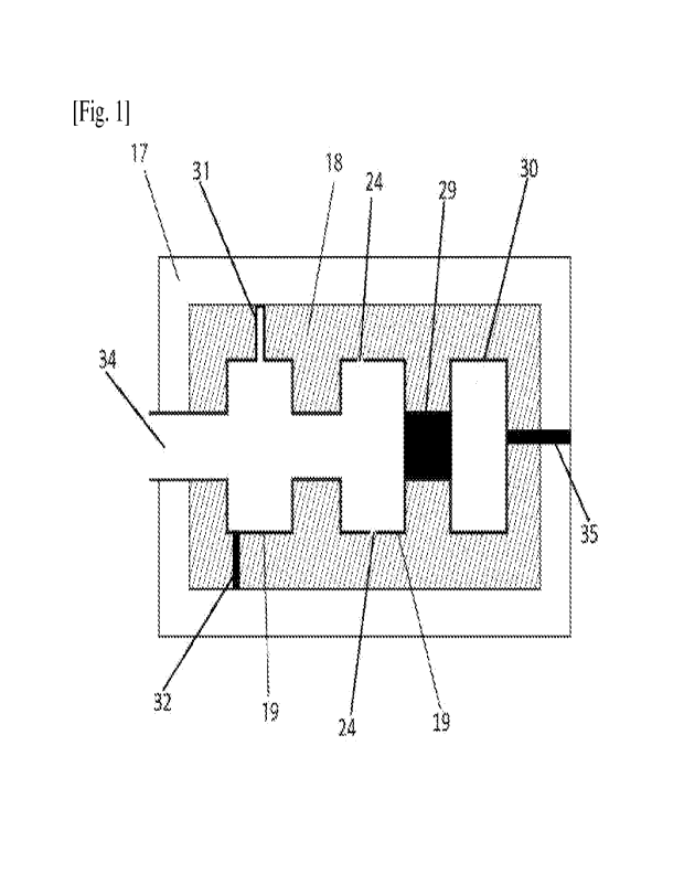
[0118] Turning to [Fig.1], a cross-section of the mould 17 is shown
that the cavity-defining
structure 19 is placed inside the mould 17 prior to moulding foam article 18
inside the
mould 17. In some applications to secure the location of the cavity-defining
structure
19 inside the mould 17, and avoid dislocating the cavity-defining structure 19
during
the moulding process, the cavity-defining structure 19 can include an
extension or any
holding means. The hollow extension 31, or solid extension 32 can be used
depending
on the application of the foam article 18. The extensions 31, and 32 can also
reinforce
the foam article 18. In one embodiment, the mould 17 can include one or more
openings 34 to allow pressurizing the cavity-defining structure during the
moulding
process.
[0119] In one embodiment, the mould 17 can be made of multiple
pieces and the cavity-
defining structure 19 can include the extension 35 that is exposed to the
outside of the
mould 17 from the opening in the mould. The end of extension 35 can be
equipped
with mechanical inserts such as hooks and buckles or other means to attach the
foam
article to other foam articles or other objects. The embodiment can be
beneficial for in-
stalling articles with minimum or no need for additional means to keep the
foam
articles in place for an application. Such an embodiment can be used for
installing
foam articles such as panels for insulation, impact protection (such as a
foldable
helmet), comfort-padding, floatation, construction or other applications that
can benefit
CA 03207743 2023- 8-8
WO 2022/172257
PCT/1B2022/051345
17
from such an arrangement.
[0120] In one embodiment, the cavity-defining structure 19 is
joined by one or more
enclosed cavity-defining structures 30 that are pressurized positively or
negatively or
at atmospheric pressure and arc connected by attachment 29 to the cavity-
defining
structure 19.
[0121] In one embodiment, the cavity-defining structure 19 includes
the opening 24 at one
or more locations in the cavity-defining structures 19. The cavity-defining
structure 19
can be pressurized positively or negatively from the opening 34 during the
moulding
process. If the cavity-defining structure 19 is positively pressurized by a
gas such as air
or steam, the pressure in the cavity-defining structure 19 allows more
cavities to be
formed at the openings 24 in the foam article 18. This allows increasing the
volume of
the cavity in the foam article 18 without increasing the size of the cavity-
defining
structure 19. If the cavity-defining structure 19 is negatively pressurized,
the foam 18
can partially or entirely enter the cavity-defining structure 19, which can
strengthen the
foam article 18 and firmly hold and anchor the cavity-defining structure 19
inside the
foam article 18.
[0122] The mould can include vents for steaming or exiting the air
inside the mould that are
not shown in [Fig.1] or other figures for keeping the drawing uncluttered with
the
prior-art information.
[0123] In an embodiment, the foam article 18 equipped with the
cavity-defining structure 19
is used for floatation. In such an embodiment, the cavity-defining structure
19 is placed
inside the mould 17, prior to introducing expanded polymer beads to create the
foam
article 18. The created foam article 18 can have better floatation, better
strength, better
durability, and also have built-in attachment means at extension 35. In an
embodiment,
the extension 35 can be used to attach the foam article to other foam
articles, vessel,
boat docking, shoreline on any other conceivable marine applications for the
foam
article 18. Once, the moulding is completed, the opening 34 can be closed or
plugged.
[0124] Turning to [Fig.21, a cross-section of the helmet 14 worn on
the head 13 is illustrated
that includes the outer shell 10, and shock-absorbing liner 11. In one
embodiment the
shock-absorbing liner 11 is equipped with the cavity-defining structure 12 at
one or
more locations to enhance the helmet perfoimance by reducing the linear and
rotational
acceleration of the head 13. In one embodiment, the cavity-defining structure
12
includes the solid extension 38 and/or hollow extension 39 at one or more
locations to
securely place the cavity-defining structure 12 inside the mould during the
moulding
process.
[0125] In one embodiment, extension 37 helps separate the shock-
absorbing liner 11 to
multiple pieces to remove the cavity-defining structure 12 after moulding. The
pieces
of the shock-absorbing 11 (not shown in [Fig.21) then will be attached
together using
CA 03207743 2023- 8-8
WO 2022/172257
PCT/1B2022/051345
18
any mechanical or chemical attachment means such as pressure, heat, in-
moulding, co-
moulding, adhesive, buckles, and a combination thereof.
[0126] In one embodiment, extension 37 is not included in the foam
article to allow the
pieces of the shock-absorbing 11 (not shown in [Fig.21) to bond to each other.
[0127] In one embodiment, the cavity-defining structure 12
comprises opening 15 to allow
pressurizing the cavity-defining structure during the moulding process.
[0128] Tn one embodiment, the cavity-defining structure 12 reaches
the inner surface 40 of
the helmet 14 at one or more locations 41.
[0129] In one embodiment, the cavity-defining structure 12 includes
the solid extensions
37,38 and/or hollow extension 39 at one or more locations to enhance the
structure of
the helmet 14.
[0130] In one embodiment, the cavity-defining structure 12 includes
other attaching means
conventionally used in foam moulding to keep the cavity-defining structure 12
in place
during moulding.
[0131] In one embodiment, one or more of the extensions 37, 38 and
39 reach the outer
surface of the shock-absorbing liner such as the inner surface 40 or the outer
shell 10
of the helmet 14 and comprise attachment means at the end part of the
extensions 37,
38 and 39 that attach to other parts of the helmet such as an inner shell, or
comfort
padding in a helmet.
[0132] In one embodiment, the extensions 37, 38 and 39 can have a
shock-absorbing ability.
[0133] In one embodiment, extensions 37, 38 and 39 reach the
outwardly or inwardly
surface of the helmet 14.
[0134] In an embodiment, the extensions 37, 38, or 39 can cover an
area of the inner surface
40 and provide a surface for placing and/or attaching the fitting liner (not
shown in
[Fig.21) or other parts such as the adjustment system, and the chin strap of
the helmet.
[0135] In one embodiment, the cavity-defining structure 12 or its
extensions 37, 38, or 39
are used to attach the fitting liner (not shown in [Fig.21) to the helmet 14.
For instance,
the cavity-defining structure 12 at locations similar to location 41 or the
extensions 37,
38, or 39 can facilitate attaching the fitting liner by providing attachment
means such
as inserts, rivets, pins, hook-and-loop attachments, snap pin baskets or holes
to attach
the fitting liner to the helmet 14.
[0136] In one embodiment, helmet parts such as fitting liner,
chinstrap, adjustment systems,
sensors, camera, adjustment mechanism, cord, chain, or other conceivable
accessories
(not shown in [Fig.21) are attached to the cavity-defining structure 12 or its
extensions
37, 38 and 39.
[0137] During the process of moulding foams, for some foams such as
EPS, steam is used
through special vents to enter or exit the foam article during the moulding
process. To
keep the drawings simple and understandable, those details that are previously
un-
CA 03207743 2023- 8-8
WO 2022/172257
PCT/1B2022/051345
19
derstood by the prior-arts in this field are not shown or explained.
[0138] In one embodiment, the cavity-defining structure 12 includes
openings or holes 42 to
increase or decrease the cavities in the foam of shock-absorbing liner 11 by
pres-
surizing positively or negatively from the opening 15 of the cavity-defining
structure
12 during the moulding process.
[0139] In one embodiment, the cavity-defining structure 12 can be
in any of the forms and
shapes described in the previous embodiments and used for helmets, or other ap-
plications.
[0140] Turning to [Fig.3], a cross-section 50 of a portion of a
helmet (coronal/frontal view)
is shown that comprises outer shell 51, part one shock-absorbing liner 52 that
comprises cavity 53 that is made in the first moulding process. The cavity-
defining
structure 54 is a layer of covering that covers the cavity 53 during the
second moulding
process to avoid polymer beads entering the cavity 53 during moulding. Part
two
shock-absorbing liner 56 is created in the second moulding process on the top
of the
cavity-defining structure 54. A design with a cross-section similar to cross-
section 50
is similar to the structure of the bone and it can enhance the performance of
the helmet
by reducing the linear and rotational acceleration of the head during impact.
It also
reduces the amount of polymer beads used in the helmet which reduced the
weight of
the helmet. Using the cavity-defining structure 54 in the design reinforces
the structure
shown in the cross-section 50.
[0141] In one embodiment, the cavity-defining structure 54 can be
flat, freeform, or curved
towards the cavity 53 or away from the cavity 53, and a combination thereof.
[0142] In one embodiment, the cavity-defining structure 54 includes
one or more holes 55 to
allow the part one shock-absorbing liner 52 to bond to the part two shock
absorbing
liner 56 in the second moulding process.
[0143] In one embodiment, the holes 55 are placed in a portion or
entire surface of the
cavity-defining structure 54.
[0144] In one embodiment, the holes 55 create a mesh surface with
spaced holes for the
cavity-defining structure 54.
[0145] In one embodiment, the average diameter of holes 55 is equal
to or smaller than the
average diameter of the polymer beads that are introduced to the mould.
[0146] In one embodiment, one or more of the holes 55 are placed on
matching raised studs
(not shown in [Fig.31) that were already created in part one shock-absorbing
liner 52 to
securely hold the cavity-defining structure 54 in place during the second
moulding
process.
[0147] In one embodiment, the cavity-defining structure 54 is a
flexible or conformable
material.
[0148] In one embodiment, the cavity-defining structure 54 is a
flexible mesh layer
CA 03207743 2023- 8-8
WO 2022/172257
PCT/1B2022/051345
comprising spaced holes.
[0149] In one embodiment, the width of part one shock-absorbing
liner 52 and part two
shock-absorbing liner 56 at a location where they meet the cavity-defining
structure
54, is wider than the width of the cavity-defining structure 54. This feature
allows part
one shock-absorbing liner 52 and part two shock-absorbing liner 56 to bond
directly
with each other at some locations and also the cavity-defining structure 54 to
be hidden
in the final foam article.
[0150] In one embodiment, the cavity-defining structure 54 is
coated with an adhesive or a
paint to better bond to part one shock-absorbing liner 52 and/or part two
shock-
absorbing liner 56.
[0151] In one embodiment, the helmet or any other objects that
benefit from such an ar-
rangement uses as many as needed the same design shown in the cross-section 50
in a
row or sandwich on the top of each other with or without the outer shell 51.
[0152] In an embodiment, the cross-section 50 belongs to a foam
article used for ap-
plications such as insulation, floatation, construction, packaging, or any
other con-
ceivable application for foam article equipped with cavity-defining structure
54 with or
without having the outer shell 51.
[0153] In an embodiment, cross-section 50 belongs to a foam article
used for construction
with or without having the outer shell 51 such that a large number of cavity
53 are
placed next to each other with a wall of foam similar to shock-absorbing line
52 in
between similar to an array of cavities (grid-like). Such cavities (i.e.,
cavity 53) can
have connected volume or be self-contained. In one embodiment, each cavity 53
in the
array of the cavity 53 is self-contained. This allows the foam article to be
suitable for
applications such as construction that customization and cutting foam are
normally
needed when blocks or panels are used to fill a space with fixed dimensions.
[0154] Turning to [Fig.4], a cross-section 46 of a portion of a
helmet (coronal/frontal view)
is shown that comprises cavity-defining structure 44 which plays the role of
an outer
shell or inner shell, cavity 47, and the shock-absorbing liner (foam article)
45. In an
embodiment, the shock-absorbing liner 45 is made to include cavity 47. In the
next
step, the outer shell 44 is attached to the shock-absorbing liner 45 using a
mechanical
or chemical attachment such as co-moulding, in-moulding, heat, pressure,
adhesive,
insert, pins, screws, strap, rivet, or a combination thereof.
[0155] In an embodiment, the cavity-defining structure 44
reinforces the foam article's
structure. Without the cavity-defining structure 44, the shock-absorbing liner
45 will
be fragile and vulnerable to damage. When the cavity-defining structure 44 is
added to
the foam structure, the foam article 46 with the correct size of the cavity 47
can absorb
shocks the same or better than a similar foam structure without the cavity 47.
[0156] In one embodiment, the object shown in [Fig.4] can be any
protective equipment to
CA 03207743 2023- 8-8
WO 2022/172257
PCT/1B2022/051345
21
protect the body or the head or used in a vehicle protective parts (e.g. car
bumper),
vehicle comforting parts, aeroplane parts, vessels, flying objects, or any
other ap-
plications of a foam article.
[0157] In an embodiment, an array of foam articles 45 and cavities
similar to the cavity 47
are placed next to each other to create the final shape of the foam article.
[0158] Turning to [Fig.51, the cross-section 69 (sagittal view) of
a helmet over the head 66 is
shown that comprises an outer shell 60, part one shock-absorbing liner 61,
part two
shock-absorbing liner 64, one or more cavities 63, and the cavity-defining
structure 62.
[0159] In one embodiment, part one shock-absorbing liner 61 along
with the outer shell 60
is made such that to have cavity 63 in the shock-absorbing liner 61. Then, in
the next
moulding process, the cavity-defining structure 62 is added to cover the
cavity 63 prior
to introducing the polymer beads to the mould to create the part two shock-
absorbing
liner 64.
[0160] In one embodiment, cavities 63 are divided by including
raised areas 67 in the part
one shock-absorbing liner. The raised areas 67 can be in any shape and form
and can
get close or reach to the cavity-defining structure 62.
[0161] In one embodiment, the raised area 67 acts as a dividing
wall between cavities 63 and
provides a desired structure for the cavity with certain strength for a given
application.
[0162] In one embodiment, the raised area 67 provides support for
securely holding the
cavity-defining structure in place.
[0163] In one embodiment, the cavity-defining structure 62 has
holes 68 in it. The holes can
be placed in any configuration or shape. Holes 68 can improve the bonding
between
part one shock-absorbing liner 61 and part two shock-absorbing liner 64. It
can also
reduce the weight of the cavity-defining structure 62. The size of holes 68
can be
selected to be the same or smaller than the average size of the polymer beads
in-
troduced to the mould in the second moulding process.
[0164] In one embodiment, the cavity-defining structure 62 is a
flexible or conformable
layer.
[0165] In one embodiment, the cavity-defining structure 62 is a
rigid layer.
[0166] In one embodiment, the cavity-defining structure 62
comprises fabric, plastic, metal,
or fibre.
[0167] In one embodiment, the cavity-defining structure 62 is a
mesh layer or screen layer
with spaced holes or openings.
[0168] In one embodiment, the foam article made by using the cavity-
defining structure is
made of any type of foam made from pre-expanded beads or foams made from the
foam ingredients in other forms or shapes.
[0169] While illustrative embodiments have been illustrated and
described, it will be ap-
preciated that various changes can be made therein without departing from the
spirit
CA 03207743 2023- 8-8
WO 2022/172257
PCT/1B2022/051345
22
and scope of the invention. Any described feature that is described in
singular or plural
form can be both in singular or plural form for a given application.
CA 03207743 2023- 8-8