Note: Descriptions are shown in the official language in which they were submitted.
CA 03206643 2023-06-27
WO 2022/140834
PCT/CA2020/051805
TRACK STRUCTURE WITH HOLLOW CENTER RAIL USABLE AS VENTILATION DUCT
TECHNICAL FIELD
[0001] The present disclosure relates to a track structure, and more
particularly to a track structure
having a hollow center rail usable as a ventilation duct.
BACKGROUND
[0002] In the mining industry, excavated ore and development (waste) rock
may be hauled from a
subterranean mine to surface level through an inclined tunnel, which may be
referred to as a "ramp" or
"drift." Various types of vehicles may be used to haul the ore, or other
payloads, up a ramp.
[0003] One type of vehicle that may be used for such hauling is a diesel
haulage truck (or simply
"diesel truck"). An example of a diesel truck used for mining is the
MinetruckTM MT5020 sold by Epiroc
Canada Inc., which has a 50-ton capacity. Diesel trucks are commonly used due
to a low capital
expenditure and versatility. However, diesel trucks are not highly ranked for
efficiency and can result in
high operating costs. This may be due to fuel consumption and cost required
for operating labourers, high
maintenance costs, increased ventilation requirement, and low energy
consumption efficiency.
[0004] To accommodate a 50-ton diesel mining truck, an inclined tunnel may
have a significant cross-
sectional area. The cross-sectional area may be dictated primarily by the
height and width of the diesel
truck. However, another factor that may warrant a larger tunnel cross-
sectional area is ventilation ducting.
[0005] A diesel mining truck engine may produce a significant amount of
exhaust gases, at least some
of which (e.g. carbon monoxide) are harmful to human health. Mining tunnels
are commonly ventilated to
minimize the risk from such exhaust to human occupants, and for other reasons,
such as regulating
temperature and dissipating dust. The amount of air that must be circulated
through the tunnel and any
associated mine for adequate safety may be significant. As such, it is not
uncommon for ventilation pipes
to have a large diameter, e.g. four feet or more. A mining tunnel may contain
one or more such ventilation
pipe(s) for conveying fresh air to a work area. As such, the cross-sectional
area of the ramp may be
required to accommodate not only the cross-sectional area of the truck but
also the cross-sectional area of
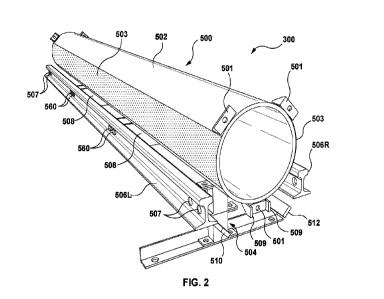
the ventilation pipe(s).
[0006] Some mining trucks, such as the ZSOTM mining truck sold by Artisan
VehiclesTM, may be
electrically powered. The absence of any emissions from such trucks may
reduce, although not eliminate,
- 1 -
CA 03206643 2023-06-27
WO 2022/140834
PCT/CA2020/051805
ventilation requirements. Nevertheless, the cross-sectional are of a ramp that
would be required to
accommodate both a smaller ventilation pipe and a conventional truck may still
be significant.
[0007] The grade of an inclined tunnel may be practically limited by the
vehicles used to haul
excavated ore to surface level. For example, a mining truck with rubber wheels
(e.g. 50-ton diesel truck)
may have difficulty hauling payloads up grades steeper than 18%. The reason is
that the truck's wheels
may lose traction at grades steeper than 18%.
[0008] When prospective mining of a mineral deposit is being considered, a
cost-benefit analysis may
be performed to ensure that the estimated value of the minerals exceeds the
estimated cost of mining the
ore. If the cost of excavating an inclined tunnel for hauling ore is too
great, there may be little incentive to
mine the ore. Valuable mineral deposits may be left untapped if the cost of
extracting them is perceived as
too high.
SUMMARY
[0009] In one aspect of the present disclosure, there is provided a modular
track segment of a track
structure usable by a wheeled vehicle for hauling a payload up an inclined
enclosed passageway, the
modular track segment comprising: a hollow center rail member configured to
act as both a center rail for
the wheeled vehicle and as a ventilation duct, the hollow center rail member
being rigid with open ends
and having, on opposite lateral faces, respective wheel contact surfaces
grippable by an opposed pair of
inwardly-biased drive wheels of the wheeled vehicle; rail support structure
depending from the hollow
center rail member; an elevated pair of rails attached to the rail support
structure, the rails being on
opposite sides of and substantially parallel to the hollow center rail member,
each rail being supported by
the rail support structure so as to provide: an upper surface suitable for
rolling engagement by a weight-
bearing wheel of the wheeled vehicle; a lower surface suitable for rolling
engagement by an undermount
wheel of the wheeled vehicle; and a lateral surface suitable for rolling
engagement by a guide wheel of the
wheeled vehicle; and at least one connector configured to facilitate
connection of the hollow center rail
member with an adjacent hollow center rail member of an adjacent modular track
segment so that
respective open ends of the center rail members are aligned.
[0010] In another aspect of the present disclosure, there is provided a
track structure usable by a
wheeled vehicle for hauling a payload up an inclined enclosed passageway, the
track structure comprising:
a hollow center rail member configured to act as both a center rail for the
wheeled vehicle and as a
ventilation duct, the hollow center rail member being rigid and having, on
opposite lateral faces, respective
wheel contact surfaces grippable by an opposed pair of inwardly-biased drive
wheels of the wheeled
- 2 -
CA 03206643 2023-06-27
WO 2022/140834
PCT/CA2020/051805
vehicle; rail support structure depending from the hollow center rail member;
and an elevated pair of rails
attached to the rail support structure, the rails being on opposite sides of
and substantially parallel to the
hollow center rail member, each rail being supported by the rail support
structure so as to provide: an
upper surface suitable for rolling engagement by a weight-bearing wheel of the
wheeled vehicle; a lower
surface suitable for rolling engagement by an undermount wheel of the wheeled
vehicle; and a lateral
surface suitable for rolling engagement by a guide wheel of the wheeled
vehicle.
[0011] In a further aspect of the present disclosure, there is provided a
method of ventilating a distal
end of an enclosed passageway, the method comprising: extending a track
structure previously installed in
the enclosed passageway towards the distal end of the enclosed passageway, the
track structure having
an open-ended hollow center rail member configured to act as both a center
rail for a wheeled vehicle and
as a ventilation duct, by: aligning an open-ended hollow center rail member of
a modular track segment
with the open-ended hollow center rail member of the track structure; and
attaching the modular track
segment to the track structure to create a substantially airtight seal between
the aligned hollow center rail
member of the modular track segment and the hollow center rail member of the
track structure; and
conveying ventilation air through the hollow center rail member of the track
structure into the hollow center
rail member of the attached modular track segment for egress from a distal
open end of the hollow center
rail member of the attached modular track segment proximately to the distal
end of the enclosed
passageway.
BRIEF DESCRIPTION OF THE DRAWINGS
[0012] In the figures which illustrate example embodiments,
[0013] FIG. 1 is a perspective view of an entrance to a conventional
inclined mining tunnel adjacent to
an entrance to an inclined mining tunnel having an installed track structure
exemplary of an embodiment of
the present disclosure;
[0014] FIG. 2 is a front, top perspective view of a modular track segment
that can be used to construct
the track structure of FIG. 1 for a wheeled vehicle to haul a payload up the
inclined tunnel;
[0015] FIG. 3 is a rear, top perspective view of the modular track segment
of FIG. 2;
[0016] FIG. 4 is a front, bottom perspective view of the modular track
segment of FIG. 2;
[0017] FIG. 5 is a front elevation view of the modular track segment of
FIG. 2;
[0018] FIG. 6 is a top perspective view of a bracket component of the
modular track segment of FIG.
2;
- 3 -
CA 03206643 2023-06-27
WO 2022/140834
PCT/CA2020/051805
[0019] FIG. 7 is a bottom perspective view of a bracket component of the
modular track segment of
FIG. 2;
[0020] FIG. 8 is a perspective view of a drive unit of a wheeled vehicle
atop the modular track
segment of FIG. 2;
[0021] FIG. 9 is a perspective view of the drive unit of FIG. 8 with the
cab portion removed to reveal
the chassis of the drive unit;
[0022] FIG. 10 is a top plan view of the chassis of FIG. 9;
[0023] FIG. 11 is a perspective view of a single wheel assembly of the
chassis of FIG. 9 in isolation
from the remainder of the chassis;
[0024] FIG. 12 schematically depicts ventilation problems that may arise
during excavation of the
tunnel of FIG. 1;
[0025] FIG. 13 schematically depicts supplementary ventilation that may be
performed in the tunnel of
FIG. 12 using the track structure of FIG. 1;
[0026] FIG. 14 is a flowchart depicting operations for ventilating a distal
end of the tunnel of FIG. 12;
[0027] FIG. 15 schematically depicts the distal end of the tunnel of FIG.
12 before the operation of
FIG. 14 is performed;
[0028] FIG. 16 schematically depicts the distal end of the tunnel of FIG.
12 as the operation of FIG. 14
is being performed;
[0029] FIG. 17 schematically depicts the distal end of the tunnel of FIG.
12 after the operation of FIG.
14 has been performed;
[0030] FIG. 18 is a front perspective view of an alternative modular track
segment of an alternative
track structure for the wheeled vehicle of FIG. 1;
[0031] FIG. 19 is a front, bottom perspective view of the alternative
modular track segment of FIG. 18;
[0032] FIG. 20 is an isometric view of an adapter track segment for
installation between a modular
track segment as shown in FIG. 2 and a modular track segment as shown in FIG.
18;
[0033] FIG. 21 is an isometric top view of an air ingress track segment
having an air inlet and a
removable fan attachment;
[0034] FIG. 22 is a side view of the air ingress track segment of FIG. 21
without the fan attachment;
and
- 4 -
CA 03206643 2023-06-27
WO 2022/140834
PCT/CA2020/051805
[0035] FIG. 23 is a top front perspective view of a further alternative
modular track segment of an
alternative track structure for a wheeled vehicle for hauling a payload up an
inclined tunnel.
DETAILED DESCRIPTION
[0036] In this document, the term "exemplary" should be understood to mean
"an example of' and not
necessarily to mean that the example is preferable or optimal in some way.
[0037] FIG. 1 is a perspective view depicting entrances to two mining
tunnels 100 and 200, each
being a form of enclosed passageway. The first mining tunnel 100 is
conventional. The second mining
tunnel 200 is new at least by virtue of the track structure 300 contained
therein, which is exemplary of an
embodiment of the present disclosure. It will be appreciated that the
depiction of tunnels 100 and 200 side
by side in FIG. 1 is to facilitate comparison and that, in practice, side-by-
side construction of such distinct
tunnels may be uncommon.
[0038] Although not visible in FIG. 1, each tunnel 100, 200 is inclined
between its entrance and a
subterranean work area. The tunnels 100, 200 are each intended for hauling
development rock (excavated
waste material) and excavated ore to the surface, each being a form of
payload. However, as will be
appreciated, the manner in which each of the tunnels 100, 200 is used for this
purpose differs.
[0039] The conventional tunnel 100 is intended for use by conventional
mining trucks 150 hauling ore
from an underground mine to surface level. The mining trucks 150 may for
example be MinetruckTM
MT5020 50-ton trucks or similar trucks, having diesel engines, rubber tires,
and a dump box.
[0040] As illustrated in FIG. 1, the conventional tunnel 100 has a
substantially rectangular transverse
cross section and a substantially flat floor 120 upon which the truck 150 is
intended to be driven. The
height and width of the example tunnel 100 is approximately 20 feet by 15
feet. As such, the cross-
sectional area of tunnel 100 is approximately 300 square feet. It will be
appreciated that these dimensions
may vary somewhat between embodiments. In some embodiments, the conventional
tunnel 100 may have
a cross-sectional shape that is non-rectangular, e.g. with an arched ceiling.
[0041] The conventional tunnel 100 of FIG. 1 further accommodates a
ventilation pipe (or duct) 180.
The purpose of the ventilation pipe 180 is to ventilate a subterranean work
area of the tunnel 100 with
fresh air from surface level. The term "work area" as used herein refers to an
area at which tunnel
excavation or mining excavation work is being performed. The work area is
typically located at the distal
end of the tunnel 100 relative to the tunnel entrance.
- 5 -
CA 03206643 2023-06-27
WO 2022/140834
PCT/CA2020/051805
[0042] Ventilation may be required at the work area to remove and/or to
avoid buildup of at least one
of: exhaust gases produced by the diesel engine of the mining truck 150;
airborne particulates, e.g. dust
contaminants produced from blasting activities during tunnel excavation;
carbon dioxide from human
exhalation; naturally occurring harmful underground gases (e.g. radon); heat;
or a combination of these. In
one example, it may be required to convey 100 cubic feet per minute (CFM) of
fresh air into a work area
for each horsepower of a diesel truck engine that is being used at or near the
work area. This metric may
vary from mine site to mine site, e.g. based on local regulatory and diesel
emission efficiency
requirements.
[0043] In the embodiment depicted in FIG. 1, the ventilation pipe 180
within tunnel 100 is a cylindrical
pipe made from steel or a plastic resin or PVC and polyester fabric material
for example. To meet
anticipated ventilation requirements, the ventilation pipe 180 may have a
diameter of approximately four
feet. The exemplary ventilation pipe 180 of FIG. 1 is suspended from the
ceiling of the tunnel 100, e.g.
using brackets (not expressly depicted), at a height sufficient for mining
trucks 150 to be able to safely
pass underneath even when fully loaded with material.
[0044] The second tunnel 200 of FIG. 1 differs from the first tunnel 100 in
at least four respects.
[0045] A first difference between tunnel 200 and conventional tunnel 100 is
that the floor of tunnel 200
has a track structure 300 mounted thereto rather than simply being a flat
surface upon which a vehicle is
intended to be driven. The track structure 300 is elevated and is designed to
carry a corresponding
electrically powered wheeled vehicle 400 for hauling ore, development rock,
personnel, equipment, or
other payloads. As will be described, the manner in which the track structure
300 and vehicle 400
cooperate provides several advantages over conventional tunnels and trucks
that may significantly reduce
initial tunnel excavation costs. The advantages include a steeper maximum
grade and the absence of any
need for one or more separate ventilation pipes similar to ventilation pipe
180.
[0046] A second difference is that the cross-sectional shape of tunnel 200
is circular rather than
substantially rectangular. The circular shape, although not strictly
mandatory, may be chosen for various
reasons. One possible rationale for the circular cross-sectional shape is that
the tunnel may be required to
extend deep underground, to reach as-yet untapped deposits. At greater depths,
lateral inward forces on a
tunnel may be so large that tunnel sidewalls, if cut vertically, would be
prone to inward buckling
("hourglassing") or inward eruption in a phenomenon known as a "rock burst." A
circular tunnel cross-
section may limit the risk of such detrimental occurrences. As will become
apparent, the installation of
track structure 300 may also avoid the need to create a substantially flat
tunnel floor, since the wheels of
- 6 -
CA 03206643 2023-06-27
WO 2022/140834 PCT/CA2020/051805
the wheeled vehicles to be driven through tunnel 200 will ride along the track
structure 300, not directly on
the floor of tunnel 200 as is the case for tunnel 100.
[0047] A third difference between the tunnels 100 and 200 is that the cross-
sectional area of tunnel
200 is significantly smaller that than of conventional tunnel 100. This can be
seen in FIG. 1, where tunnels
100 and 200 are depicted substantially to scale, with a person 110 depicted
between them to provide a
rough benchmark for size. In this example, tunnel 200 is approximately eight
feet in diameter and thus has
a circular cross-sectional area of approximately 50 square feet. That cross-
sectional area is approximately
six times smaller than the 300 square foot cross-sectional area of
conventional tunnel 100. The
significantly smaller cross-sectional area of tunnel 200 may considerably
diminish the cost of excavating
the tunnel in comparison to excavating conventional tunnel 100. This is by
virtue of the smaller amount of
material (e.g. rock) that must be excavated to create a given length of tunnel
200 as compared to the same
length of wider and taller tunnel 100. The reduction in tunnel size may also
significantly reduce the
materials required for supporting the excavation (e.g. mechanical support
types, rebar, screen, cable bolts,
and/or schotcrete). As will be appreciated, the small cross-sectional area of
tunnel 200 is attributable, at
least in part, to the fact that the track structure 300 has a hollow center
rail that is usable as a ventilation
duct, thereby avoiding the need to accommodate one or more separate
ventilation pipe(s).
[0048] A fourth difference between tunnel 200 and conventional tunnel 100,
not discernible in FIG. 1,
is that the incline of the former is steeper than that of the latter. In
particular, tunnel 200 can have a grade
less than or equal to 50% (i.e. 26.57 degrees or 1:2 gradient). In contrast,
the maximum grade of tunnel
100 may be 18%. The steeper grade of tunnel 200 is made possible by
cooperation between the track
structure 300 and the wheeled vehicle 400, which provides robust traction that
is not dependent on gravity
and that permits payloads to be hauled even at a steeper grade. As will become
apparent, the steeper
grade of tunnel incline generally reduces the length of tunnel required to
reach a target depth.
[0049] For clarity, the maximum 50% grade for tunnel 200 is determined in
part by material angle of
repose limits when carrying rock, sand, or gravel materials. The reason is
that, at steeper grades than
50%, the angle of repose limits may be exceeded, and such materials may
naturally shift and spill out of
open-top dump boxes of wagon cars that may form part of the wheeled vehicle
400 (not expressly
depicted).
[0050] To facilitate/expedite installation, the track structure 300 may be
assembled from multiple
modular track segments. A single exemplary, straight modular track segment 500
of track structure 300 is
depicted in FIGS. 2-5. In particular, FIGS. 2, 3, and 4 illustrate the modular
track segment 500 in front top
- 7 -
CA 03206643 2023-06-27
WO 2022/140834
PCT/CA2020/051805
perspective view, rear top perspective view, and front bottom perspective
view, respectively. FIG. 5 is a
front elevation view of the track segment 500.
[0051] The depicted modular track segment 500 is a straight section of
track. It will be appreciated
that other types of modular track segments, e.g. laterally or vertically
curved segments of various curvature
radii, may also be used, possibly in combination with straight segments, to
assemble a track structure 300
whose geometry conforms to that of tunnel 200 or of surface terrain.
[0052] The modular track segment 500 of FIGS. 2-5 is comprised of multiple
components, including a
center rail member 502, a support member 504, an elevated pair of rails 506L
and 506R (generically or
collectively rail(s) 506), rail support structure 508 comprising multiple
brackets for attaching the rails 506 to
the center rail member 502, and a pair of electrical conductors 510 and 512.
These components may for
example be formed into the unified modular track segment 500 depicted in FIGS.
2-5 in a factory setting.
The track segment 500, possibly along with other track segments, may then be
delivered to a mining
excavation site for interconnection to form a track structure 300 on-site, as
will be described.
[0053] The center rail member 502 is a rigid, hollow member with open ends.
The center rail member
502 serves two primary purposes.
[0054] The first primary purpose of center rail member 502 is to act as a
center rail for the drive unit of
the wheeled vehicle 400. As will be described, a pair of opposed, inwardly
biased, horizontally oriented
drive wheels of the wheeled vehicle 400 is configured to grip or squeeze the
center rail member 502
therebetween. The center rail member 502 accordingly has wheel contact
surfaces 503 on opposite sides,
i.e. on its outwardly facing lateral faces. In the illustrated example, each
wheel contact surface 503 spans
approximately 60 degrees of the cylindrical pipe circumference. When the drive
wheels are made to rotate
(in mirror image) on opposite sides of the gripped center rail member 502,
they effectively pull themselves
along the track structure 300 and thereby propel the wheeled vehicle 400
forward or backward.
[0055] The second primary purpose of center rail member 502 is to act as a
ventilation duct, at least
during the tunnel excavation process. It is for that reason that the center
rail member 502 is hollow with
open ends. A gasket or 0-ring 505 (see FIG. 3) at the end of the hollow rail
member 502 may promote an
airtight seal between the center rail member 502 of the track segment 500 and
a center rail member of an
adjacent track segment. This may reduce the escape of ventilation air from the
pipe to maintain efficiency
and/or minimize ingress of contaminant materials or gases at track segment
joints. The gasket 505 may for
example be made from a resilient or elastic material, such as rubber.
- 8 -
CA 03206643 2023-06-27
WO 2022/140834
PCT/CA2020/051805
[0056] The dual role of member 502 as both a center rail and as a
ventilation pipe promotes efficient
use of cross-sectional tunnel space. For example, the need for a separate,
possibly large diameter
ventilation pipe, such as ventilation pipe 180 of FIG. 1, in the tunnel, may
be avoided. This may help to
reduce tunnel excavation costs.
[0057] In the present embodiment, the center rail member 502 is a steel
pipe with a 1-foot diameter.
For some embodiments of steel pipe, the wall thickness may be one-half inch.
The shape, composition,
and dimensions of the hollow center rail member 502 may vary between
embodiments. The rigidity of the
center rail member 502 should be suitable for withstanding the lateral
squeezing forces from the drive
wheels without significant deformation. Factors such as the number of drive
units per wheeled vehicle 400
may have a bearing on the required rigidity, e.g. because a greater number of
drive units may reduce the
degree of squeezing force required by any given drive unit for maintaining a
desired coefficient of friction.
[0058] The wheel contact surfaces 503 may have a high-friction or abrasive
surface for maximizing
traction with the drive wheels. The extent to which this is required may be
embodiment-specific, e.g. based
on various factors, possibly including one or more of tunnel incline, expected
payload weight, the frictional
properties of the material from which the drive wheels are made, atmospheric
conditions, and the presence
of moisture (rain/dripping water), snow, and dust. If present, the high-
friction or abrasive surface may be
surface finishing or abrasion marking directly upon the surface of the center
rail member 502.
[0059] Adjacent modular track segments 500 may be bolted together at
connector flanges 501 (each
being a form of connector) with respective open ends of the center rail
members 502 being aligned to
permit passage of ventilation air therethrough. In the present embodiment,
three such connector flanges
501 extend radially from the periphery of each end of the cylindrical center
rail member 502, equally
spaced from one another about its circumference (120 degrees apart in this
embodiment). At least one of
the connector flanges 501 may have guides 509 (see e.g. FIG. 2) for
facilitating alignment with a
corresponding connector flange 501, which lacks such guides 509, of the
adjacent center rail member 502
prior to interconnection of adjacent track segments 500.
[0060] The center rail member 502 acts as the primary supporting member or
spine for the track
structure 300. In this capacity, the center rail member 502 supports not only
its own weight and that of the
rails 506 of modular track segment 500, but also the weight of the wheeled
vehicle 400 and its payload
when it drives over the modular track segment 500.
[0061] Support member 504 elevates the center rail member 502, and thus the
track structure 300 of
which the center rail member 502 is a part, above a surface (floor) of a
tunnel 200 in which the track
structure 300 is installed. The support member 504 supports the weight of the
track structure 300 as well
- 9 -
CA 03206643 2023-06-27
WO 2022/140834
PCT/CA2020/051805
as that of any passing wheeled vehicle 400 and its payload. One rationale for
elevating the track structure
300 is to reduce the requirement for a substantially flat tunnel floor, as in
conventional tunnel 100. A
rationale for elevating the rails 506 specifically is to provide clearance for
undermount wheels of the
wheeled vehicle 400 to roll along an underside of the rails 506, as will be
described below.
[0062] The modular track segment 500 depicted in FIGS. 2-5 has only one
support member 504. The
example support member 504 is disposed closer to one end of the track segment
500 than to the other. In
this example, the modular track segment 500 is approximately 9 feet long, and
the support member 504 is
positioned approximately 1.5 feet from one end (i.e. at approximately 15% of
track segment length). This
design may be considered counter-intuitive, e.g. because a sole support member
504 that is so
longitudinally offset may be considered ill-suited for elevating the entirety
of track segment 500, at least
independently of other track segments.
[0063] Nevertheless, the longitudinally offset support member 504 permits
the track structure 300 as a
whole to be conveniently elevated. The reason is that the track structure 300
is made up of multiple
modular track segments 500 connected together end-to-end. In that arrangement,
each support member
504 may support not only the end of the modular track segment 500 of which it
is a part, but also a portion
of the immediately adjacent interconnected modular track segment 500.
Moreover, the sole support
member 504 of a modular track segment 500 may facilitate vertical alignment of
adjacent modular track
segments 500 during installation of a track structure 300 within a tunnel, as
will be described.
[0064] The use of only one support member 504 per modular track segment 500
may also facilitate
installation. The reason is that each support member 504 of the present
embodiment is intended to be
anchored to the tunnel floor. Fewer support members 504 means that less time
and effort may be required
for such anchoring.
[0065] As perhaps best seen in FIGS. 4 and 5, the example support member
504 has a base portion
520, an adjustable-height leg portion 522 comprising two stacked leg segments
524, and a shoulder
portion 526.
[0066] The base portion 520, which may be referred to as an anchor plate,
is an elongate member
oriented transversely to the center rail member 502. The extent of the base
portion 520 in the transverse
dimension of the example modular track segment 500 is greater than the spacing
between rails 506L and
506R. In the present embodiment, the base portion 520 constitutes steel angle
iron with holes to
accommodate bolts (e.g. mechanical anchor bolts, such as HiltiTM anchor bolts)
or other fasteners used to
anchor the modular track segment 500 to the tunnel floor. The anchoring
requirements may vary
depending on the surface type and degree of tunnel incline. The design of the
base portion 520 may vary
- 10 -
CA 03206643 2023-06-27
WO 2022/140834
PCT/CA2020/051805
in alternative embodiments. For example, the length, width, and/or shape of
the base portion may be
varied.
[0067] The leg portion 522 of support member 504 has an adjustable length
(height). This may allow
variations in tunnel floor topography to be accommodated while keeping the
grade of adjacent modular
track segments substantially consistent. In the present embodiment, the length
of the leg portion 522 can
be adjusted by changing the number of leg segments 524 that are used to
comprising the leg portion 522.
Each leg segment 524 of the instant embodiment has flanges 525 at its opposite
ends, each flange with a
hole therethrough. The flanges facilitate interconnection of leg segments 524
to one other or to other
components, e.g. the base portion 520 or shoulder 526, using fasteners such as
bolts (not expressly
depicted). In alternative embodiments, the length of the support members may
be adjustable in other ways
besides stackable leg segments 524, e.g. telescopically.
[0068] The shoulder 526 of support member 504 (FIG. 4) may be permanently
attached to the
underside of the center rail member 502, e.g. by welding. The shoulder 526
transfers the weight of the
center rail member 502 and its attached rails 506 to the leg portion 522.
[0069] The elevated pair of rails 506L, 506R (collectively rails 506) will
bear a weight of the wheeled
vehicle 400 and any payload that it may carry. The rails 506 may promote
superior wheeled vehicle
stability and may reduce wear and/or damage to connections (joints) between
adjacent modular track
segments 500, at least in comparison to a hypothetical alternative track
structure lacking rails 506 in which
the wheeled vehicle were to ride directly atop the center rail member.
[0070] The rails 506 used in the depicted embodiment are standard steel
rails as commonly used for
railway or subway systems. As such, each rail 506L, 506R has a broad head
portion, narrow web portion,
and a wide foot portion (not expressly labeled). The weight of the wheeled
vehicle 400 is borne by non-
drive wheels that roll along an upper surface 540 of a head portion of the
rails 506, as will be described.
The use of standard rails is not absolutely required.
[0071] The pair of rails 506 flanks the center rail member 502 and is
substantially parallel thereto. In
this disclosure, the term "flank" means to be on opposite sides of the center
rail member 502, although not
necessarily horizontally aligned with the axis of center rail member 502. In
this embodiment, the rails 506L
and 506R are disposed on the left and right sides, respectively, of center
rail member 502 but closer to the
ground. Put another way, the vertical positioning of the rails 506 in the
present embodiment is at or near a
lower extent of the center rail member 502 (see e.g. FIG. 5), e.g. with
approximately three-quarters of the
center rail member 502 above the upper surface 540 of the rail 506. This
vertical positioning of the rails
506 relative to the center rail member 502 may help to reduce tunnel height
requirements, at least in
-11-
CA 03206643 2023-06-27
WO 2022/140834
PCT/CA2020/051805
comparison to a hypothetical alternative track structure lacking rails 506 in
which the wheeled vehicle rides
directly atop the center rail member.
[0072] The size of the gap between each rail 506 and the center rail member
502 may be chosen with
a view to reducing the likelihood that debris, such as falling rock, will
become wedged between the rail 506
and the center rail member 502. Such an occurrence could potentially be
disastrous, risking equipment
damage or possibly vehicle derailment as a wheeled vehicle 400 passes by. The
size of the gap may be
chosen based on the grid size of a wire (e.g. rebar) mesh that may be applied
to the tunnel ceiling with a
view to limiting rockfalls. A common grid size is four inches square. In that
case, the gap between each rail
506 and the center rail member 502 may be just over four inches, based on the
logic that any rock small
enough to pass through that size grid will likely be too small to become
wedged in a gap of that size.
[0073] Each end of each rail 506 of the present embodiment has a pair of
transverse through holes
507. The through holes 507 are for attachment of a splice bar (also known as a
"fish plate") for splicing the
rail 506 to a corresponding rail of an adjacent modular track segment 500. In
alternative embodiments, the
rails of adjacent modular track segments may be interconnected in other ways.
[0074] The rails 506L, 506R of the modular track segment 500 are attached
to the center rail member
502 by way of rail support structure, which in the present embodiment
comprises multiple brackets 508
(see e.g. FIG. 4). In the present embodiment, each modular track segment 500,
which may be
approximately 9 feet long, includes two brackets 508 spaced approximately 3
feet apart. FIGS. 6 and 7
depict a single example bracket 508 in isolation, in top perspective view and
bottom perspective view,
respectively.
[0075] As illustrated in FIGS. 6 and 7, bracket 508 is generally cradle-
shaped, with a central
indentation 550 in an upper middle portion thereof. The indentation has a part-
circular profile with a radius
generally matching the curvature of the outer surface of the center rail
member 502. The indentation 550 is
for receiving an underside of the center rail member 502, to which the bracket
508 may be attached, e.g.
by welding.
[0076] A vertical plate 552, 554 at each respective end of bracket 508 has
a pair of apertures 555
therethrough (see FIGS. 6 and 7). These apertures 555 are for receiving
removable fasteners, such as
bolts 560 (e.g. as shown in FIGS. 2 and 3), that will removably attach a
standard rail 506 to the bracket
508. The standard rails 506 are removably attached because they may wear over
time and may require
replacement. In the present embodiment, each bolt 560 passes through one of
the apertures 555 in
vertical plate 552 or 554 and through a similar aperture in the standard rail
506.
- 12 -
CA 03206643 2023-06-27
WO 2022/140834
PCT/CA2020/051805
[0077] The bracket 508 is sized so that, when standard rails 506L and 506R
have been attached to
plates 552 and 554 respectively, the desired track spacing is achieved. In the
present embodiment, the
separation distance between rails 506L and 506R is approximately 14 inches,
but this distance may vary
between embodiments. The ends of the example bracket 508 of the present
embodiment extend slightly
beyond the lateral extent (outer diameter measured horizontally) of the center
rail member 502 when
attached in place.
[0078] Referring to FIGS. 6 and 7, it can be seen that the bracket 508 also
defines downwardly facing
mounting surfaces 561 and 563 for mounting electrical conductors 510 and 512
(e.g. as shown in FIGS. 2
and 3) respectively to bracket 508. The conductors 510, 512 will be mounted
thereto so that their exposed
contact surfaces are downwardly facing to at least some extent. This
orientation may reduce a risk of dust
or debris buildup on the contact surfaces of the conductors which could
interfere with electrical connectivity
with electrical contacts on the drive unit of the wheeled vehicle. The
conductors may be separated from the
mounting surfaces 561, 563 by an electrical insulator (not illustrated). The
conductors 510, 512 span the
length of the modular track segment 500 so that electric current can be
carried along the entire length of
the track structure 300.
[0079] The wheeled vehicle 400 is designed specifically for driving on
track structure 300. To illustrate
the manner in which the wheeled vehicle 400 engages the track structure 300,
an example drive unit
(locomotive) 600 of the vehicle 400 is shown in FIG. 8, in perspective view,
on an example modular track
segment 500. The drive unit 600 may be connected to a series of other cars
that collectively make up the
wheeled vehicle 400, at least some having dump buckets for hauling a payload.
If necessary, one or more
additional drive units 600 may be added in series, e.g. for greater hauling
power.
[0080] The drive unit 600 has a cab 602 for a human occupant who will act
as the vehicle driver. It is
not strictly required for the wheeled vehicle 400 to be driven by a human
operator occupying a vehicle cab
602. In some embodiments, the wheeled vehicle 400 may be designed for
automated or remote operation.
In that case, the structure of the drive unit 600 may differ, e.g. omitting
seat and windshield components in
favor of cameras or other sensors.
[0081] Referring to FIG. 8, the cab 602 sits atop, and is attached to, a
chassis 604. The chassis 604 is
more readily visible in FIG. 9, which shows the drive unit 600 in perspective
view with cab portion 602
removed, and in FIG. 10, which show the chassis 604 in top plan view without
the track segment 500.
[0082] As illustrated in FIGS. 9 and 10, the chassis 604 has a central
frame member 606, a drive
system 608, and two wheel assemblies 630A, 630B.
- 13 -
CA 03206643 2023-06-27
WO 2022/140834
PCT/CA2020/051805
[0083] The central frame member 606 is a rigid elongate member that may be
considered as the spine
of the chassis 604. All other components of chassis 604 are attached, directly
or indirectly, to the central
frame member 606.
[0084] The drive system 608 is responsible for propelling the drive unit
600 of wheeled vehicle 400
along the track structure 300. To that end, the drive system 608 includes two
drive wheels 610, two electric
motors 612, and a traction system 614, among other components.
[0085] The two drive wheels 610 may for example be automotive or industrial
tires, i.e. inflatable and
made from rubber, or possibly a solid (not inflatable) tire. The use of a
resilient material such as rubber for
the drive wheels 610 may maximize traction against the wheel contact surfaces
503 of center rail member
502. The drive wheels 610 are disposed on either side of the central frame
element 606 of chassis 604, i.e.
on opposite sides of the center rail member 502 of the track segment 500, and
are oriented substantially
horizontally, i.e. with their axes of rotation being substantially vertical.
[0086] Each drive wheel 610 is driven by a respective one of the electric
motors 612. A planetary
gearbox 613 associated with each electric motor 612 provides torque conversion
for turning the associated
wheel 610 with suitable torque for propelling the vehicle 400 according to
current operating conditions. The
planetary gearbox 613 is used as a gearing reduction, similar to an automotive
car starter. The torque may
be monitored and varied during operation by the electric motor 612 using
Variable Frequency Drives
(VFDs). The drive wheels 610 rotate in opposite directions, i.e. in mirror
image, because they grip the
center rail member 502 from opposite sides.
[0087] Each electric motor 612 is powered by electricity from a transformer
(not visible in FIG. 9) that
is part of drive unit 600. The transformer is electrically coupled to a pair
of electrical contacts located on
the underside of the chassis 604 (also not visible in FIG. 9). The electrical
contacts are biased against
contact surfaces of the electrical conductors 510 and 512, respectively, of
track structure 300, e.g. in a
similar manner to electrical contacts used on subway train cars, to establish
electrical contact therewith.
[0088] The traction system 614 of the drive unit 600 is responsible for
causing the drive wheels 610 to
grip or squeeze the center rail member 502 from opposite sides with a gripping
force F, represented in
FIG. 10 by inwardly pointing arrows. In the present embodiment, the gripping
force F is generated by
opposed hydraulic cylinders 616 (a form of biasing means), which bias the
drive wheels 610 laterally
towards one another. The traction system 614 is operable to manually and/or
automatically adjust the
degree of bias, i.e. the gripping force F. The forces may be monitored by in-
line pressure sensors and
adjusted by a hydraulic pump and accumulator. The forces applied may also be
monitored by a Variable
Frequency Drive for wheel traction and slip. The traction system 614 can thus
maintain traction between
-14-
CA 03206643 2023-06-27
WO 2022/140834
PCT/CA2020/051805
drive wheels 610 and center rail member 502 regardless of dynamically
changeable parameters, e.g.
changes in the contact surface conditions, moisture, temperature, degree of
incline, and center rail
member 502 thickness. These conditions may be sensed through VFD automation
controls, in a similar
manner as an electric car.
[0089] To facilitate the dynamic adjustment of gripping force F, the
lateral position of each drive wheel
610 is dynamically adjustable, as follows. Each drive wheel 610 is mounted at
a distal end of a respective
arm 618 whose length is adjustable (see e.g. FIG. 10). The two arms 618 extend
in opposite directions
laterally from the central frame member 606 of chassis 604. Each arm 618 has a
fixed proximal portion
620 and a movable distal portion 622 terminated by a supporting member 623.
The length of the arm 618
may be adjusted by telescopically sliding (translating) the distal movable arm
portion 622 within (with
respect to) the fixed proximal arm portion 620. The length of the arms 618 may
be adjusted to
accommodate the required squeeze force when maintaining traction of the tires
and for the drive unit to
transfer from one center rail member width to another. To prevent dust or grit
from interfering with
slidability, contact surfaces may be greased and/or suitable surface
materials, such as Teflon TM for
example, may be used.
[0090] At the distal end of each arm 618, a supporting member 623, having a
J-shaped profile in the
present embodiment, supports the electric motor 612 and the planetary gearbox
613. In the depicted
embodiment, the bottom of the J-shaped supporting member 623 attaches to the
planetary gearbox 613.
[0091] The adjustable bias of drive wheels 610 against the wheel contact
surfaces 503 of center rail
member 502 allows robust traction to be maintained between wheeled vehicle 400
and track structure 300,
even under varying conditions. As a result, the wheeled vehicle 400 can be
reliably driven at steeper
grades than conventional mining trucks 150, for the following reason.
[0092] A conventional mining truck 150 relies solely upon gravitational
force to establish traction
between its wheels and the surface of the road. On a flat surface, gravity
presses the truck tires directly
downwardly (orthogonally) onto the road surface, and traction is maximized.
The steeper the grade, the
lesser the component of gravity that presses the tires directly (orthogonally)
into the road surface. As such,
tire traction becomes progressively worse at steeper angles, all other things
being equal.
[0093] In contrast, the disclosed traction system 614 is not dependent on
gravitational force. The
inwardly biased drive wheels 610 can continue to apply force F upon the center
rail member 502 to
maintain traction even at steeper grades. This allows the tunnel 200 (FIG. 1)
in which the track structure
300 is installed to be dug at a steeper grade than a conventional tunnel 100
without sacrificing vehicle
traction. Consequently, tunnel excavation costs may be reduced in comparison
to excavating a tunnel at a
- 15 -
CA 03206643 2023-06-27
WO 2022/140834
PCT/CA2020/051805
shallower grade, since the length of a tunnel dug at a steeper grade may be
shorter than the length of a
tunnel dug at a shallower grade.
[0094] As shown in FIGS. 9 and 10, the wheel assemblies 630A and 630B
(collectively and
generically wheel assembly/ies 630) of drive unit 600 are disposed at the
front and rear end, respectively,
of the chassis 604. A single example wheel assembly 630 is shown in
perspective view in FIG. 11, in
isolation from the remainder of chassis 604. The rails 506L, 506R are also
illustrated in FIG. 11, with the
remainder of the track structure 300 being omitted, so that that the
interaction between the wheels of the
assembly 630 and the rails 506 can more readily be seen.
[0095] As illustrated in FIG. 11, the wheel assembly 630 comprises a
generally inverted U-shaped
frame 632 having two downwardly pointing prongs 633. Each prong 633 has three
wheels attached
thereto: a top wheel 640; a side wheel 642; and an undermount wheel 644.
[0096] The top wheel 640 has a horizontal rotation axis and is positioned
to roll along an upper
surface 540 of the rail 506, which in this embodiment is the upper surface 540
of the head portion of the
standard rail 506. The upper surface 540 is suitable for rolling engagement by
the top wheel 640, e.g. is
even and lacks any wheel obstructions. The wheel 640 bears/transfers the
weight of the wheeled vehicle
400 from frame 632 to the rail 506 and thus may be referred to as a weight-
bearing wheel. The diameter of
the top wheel 640 may be larger than that of the side and bottom wheels 642
and 644. Larger diameter
wheels may reduce rolling resistance with increased efficiency due to lesser
frictional losses compared to
smaller wheels.
[0097] The side wheel 642 has a vertical rotation axis and is positioned to
roll along a lateral surface
of the rail 506. In this embodiment, the side wheel rolls along the outer
lateral surface 542 of the head
portion of the standard rail 506. The lateral surface 542 is suitable for
rolling engagement by the side
wheel 642, e.g. is even and lacks wheel obstructions. For clarity, the side
wheel 642 does not roll along the
narrower web portion of the standard rail 506, in view of obstructions that
may protrude outwardly from that
surface (e.g. bolts 560 splice bars, or the like). The side wheels 642 are
collectively intended to limit side-
to-side shifting of the drive unit 600, and of the wheeled vehicle 400 of
which the drive unit 600 is a part,
with respect to the rails 506, which may reduce a risk of vehicle derailment.
Each side wheel 642 may be
referred to as a guide wheel. The diameter of the side wheel 642 is smaller
than that of the top wheel 640,
at least in part to minimize a width of the wheeled vehicle 400.
[0098] The undermount wheel 644 has a horizontal rotation axis and is
intended to roll along a lower
surface (underside) 544 of the rail 506. In this embodiment, the undermount
wheel 644 rolls along an
underside of the foot portion of standard rail 506. This wheel is intended to
prevent the drive unit 600 from
- 16 -
CA 03206643 2023-06-27
WO 2022/140834
PCT/CA2020/051805
lifting off the standard rails 506, to reduce a risk of derailment. The lower
surface 544 is suitable for rolling
engagement by the undermount wheel 644, e.g. is even and has sufficient ground
clearance for the wheel
644. Minimizing a diameter of the undermount wheels 644 may minimize the
required ground clearance.
[0099] The top wheel 640, side wheel 642, and undermount wheel 644 on each
prong 633 of the U-
shaped frame 632 are arranged in mirror image to those of the other prong 633.
Collectively, these six
wheels may be considered to surround the pair of rails 506L, 506R from the
top, bottom, and outside, as
best seen in FIG. 11. This arrangement may minimize a risk of derailment of
the drive unit 600 from track
structure 300.
[00100] Each of wheels 640, 642, and 644 is non-flanged. It will be
appreciated that pairs of flanged
wheels interconnected by rigid axles are commonly used on conventional trains
for lateral stability on train
tracks. However, such an approach would be ill-suited for the track structure
300 because the center rail
member 502 would block or obstruct such rigid axles. Non-flanged wheels may
beneficially provide a
lower-friction interaction between wheels and rails (as compared to flanged
wheels), which may provided
improved efficiency and reduced rail wear compared to flanged wheels. The
wheels 640, 621, and 644
may for example be made from steel, nylon, or polyurethane materials, or a
combination of these.
[00101] The U-shaped frame 632 is sized and shaped so that, when the wheel
assembly 630 rolls
along the rails 506, the frame 632 clears (does not come into contact with)
the center rail member 502.
[00102] A pivot rod 650 through the middle of the U-shaped frame 632 serves
as a point of attachment
of the wheel assembly 630 to the central frame member 606. This pivot rod 650
allows side-to-side (one-
dimensional) pivoting of the wheel assembly 630 with respect to the central
frame member 606. The pivot
may be used for the front and rear wheel assemblies of a lead car of the
wheeled vehicle 400, which may
be drive unit 600. This may facilitate navigation through lateral and
horizontal turns in the track structure
300.
[00103] FIGS. 12 and 13 are schematic depictions of tunnel 200, during its
excavation, as track
structure 300 is being installed. The installed portion of track structure 300
that is visible in FIGS. 12 and
13 is made up of multiple modular track segments 500A, 500B, and 500C that
have been interconnected
and anchored to the tunnel floor 202. As will be described, the track
structure 300 may be assembled
piecemeal through attachment of additional modular track segments 500 just
behind a work area 230 in
which the tunnel is being excavated. Where installation is to be performed in
a location lacking a solid rock
surface, concrete pads or other methods of securing the track, e.g. screw
posts, may be used.
- 17 -
CA 03206643 2023-06-27
WO 2022/140834
PCT/CA2020/051805
[00104] As illustrated in FIGS. 12 and 13, the topography of the tunnel
floor 202 may be uneven. This
my for example be due the excavation techniques used to form the tunnel 200.
These techniques may for
example involve drilling holes in a rock face at a terminus (distal end) of
tunnel 200, packing the holes with
explosives, discharging the explosives to break the rock apart into rubble,
and removing the rubble. To
compensate for any unevenness in the floor 202 (see FIG. 12), the length of
each support member 504A,
504B, and 504C of modular track segments 500A, 500B, and 500C respectively may
be suitably adjusted.
In the result, the longitudinal axes of track segments 500A, 500B, and 500C
may be substantially aligned
so that the track structure 300 is substantially straight.
[00105] The depicted portion of tunnel 200 may be considered to have two
sections: a well-ventilated
section 210 and a poorly ventilated section 220.
[00106] The well-ventilated section 210 may be ventilated by industrial
fans at surface level (not
depicted) that blow fresh air into the entrance of tunnel 200. A vertical
borehole (referred to as a "raise")
212 that has been drilled into tunnel 200 from surface level provides an exit
path for exhaust. As such,
fresh air may continuously circulate in a loop 214 that includes the well-
ventilated section 210. The raise
212 may be one of multiple raises drilled at regular or predetermined points
along the length of the tunnel
200.
[00107] In contrast, the poorly ventilated section 220 of tunnel 200 may be
considered as a ventilation
"dead zone" by virtue of being outside the circulation loop 214 of fresh air
that flows in from surface level
and out through raise 212 (see FIG. 12). As such, harmful gases, dust, and/or
heat may accumulate in this
"dead end" section 220 at the distal end of tunnel 200. These may pose a
significant risk to any mining
personnel occupying tunnel section 220, who may be required to perform further
excavation work at the
work area 230, e.g. to further extend the tunnel 200.
[00108] To reduce such risk to any mining personnel occupying the poorly
ventilated section 220, the
hollow center rail member 502 of the track structure 300 can be used to
provide supplementary ventilation
in addition to whatever ventilation may be provided to tunnel section 210 via
loop 214. This supplementary
ventilation is depicted in FIG. 13. In particular, supplementary fresh air
(ventilation) 216 may be blown into
an open end of the center rail member 502 of track structure 300 at surface
level, or possibly at an interval
along the track structure 300 having fresh air provided by mine ventilation,
e.g. using the mechanism
depicted in FIGS. 21 and 22, described below. The fresh air may be conveyed
along the length of the track
structure 300 until it exits the open end 575 of the center rail member 502 of
the last modular track
segment 500C.
- 18 -
CA 03206643 2023-06-27
WO 2022/140834
PCT/CA2020/051805
[00109] Operation 700 for ventilating a distal end of a tunnel 200 (or
other enclosed passageway) using
a track structure 300 for wheeled vehicles 400 is depicted in the form of a
flowchart in FIG. 14. Operation
700 will be described in conjunction with FIGS. 15 to 17, which schematically
depict the tunnel 200 during
various stages of operation 700.
[00110] It is presumed that, at the commencement of operation 700, the
initial state of the tunnel 200 is
as shown in FIG. 15. In particular, the installed track structure 300 has been
assembled by interconnecting
modular track segments 500A, 500B, and 500C. The open-ended hollow center rail
members 502A, 502B,
and 502C, respectively, of these segments have been aligned and interconnected
with one another,
collectively forming a continuous, substantially airtight ventilation duct. It
is further presumed that fresh air
216 from surface level or other area of fresh air is being blown, e.g. using
the mechanism shown in FIGS.
21 and 22, through the hollow center rail members 502A, 502B, and 502C and is
exiting the open end 575
of the latter component. A new modular track segment 500D to be used for
extending the track structure
300 initially rests on the tunnel floor 202.
[00111] In a first operation, the track structure 300 is extended towards a
distal end of the enclosed
passageway (tunnel) 200 (operation 702, FIG. 14). This operation may be
performed in two steps.
[00112] In a first step (702A), the open-ended hollow center rail member
502D of the new modular
track segment 500D is aligned with the open-ended hollow center rail member
502C of the installed track
structure 300. Referring to FIG. 16, alignment may be effected by first
placing a base portion 520D of the
sole support member 504D on the tunnel floor 202 at its likely point of
anchoring. This establishes a pivot
point for the modular track segment 500D. If necessary, a height of the
support member 504D may be
adjusted before the pivot point is established, e.g. with a view to promoting
axial alignment of the modular
track segment 500D with the installed track structure 300. The required height
may be measured prior to
placement of the rail section and can be adjusted if necessary once modular
track segments are
connected.
[00113] In a second step (702B), the modular track segment 500 is pivoted
on the pivot point by raising
or lowering an opposite (here, uphill) proximal open end of the center rail
member 502D for alignment with
the open end of center rail member 502C of the track structure 300. Alignment
may be facilitated by the
guides 509 on the connector flange 501 of the center rail member 502C (see
e.g. FIG. 5).
[00114] The location of pivot point (base portion 520D) closer to the
distal open end 575 of center rail
member 502D than to its proximal (uphill) end may be beneficial, because it
may minimize the impact to
track straightness of choosing a less-than-ideal height for the support member
504D. In this context, "less
than ideal" refers to a height of support member 504D that does not yield
perfect axial alignment between
- 19 -
CA 03206643 2023-06-27
WO 2022/140834
PCT/CA2020/051805
track structure 300 and the modular track segment 500D in the vertical
dimension. The impact may be
minimized in the sense that whatever angular misalignment between the new
modular track segment 500D
and the installed track structure 300 may result from an imperfectly chosen
height of support member
504D would likely be small. The reason is that any inaccuracy in the chosen
height of support member 504
would likely be dwarfed by the distance between the to-be-connected end of the
segment 500D and the
support member 504D. Therefore, any resultant angular axial misalignment of
the new modular track
segment 500D with the installed track structure 300 would likely be limited to
a few degrees. Put another
way, the likelihood of any significant angular discontinuities between track
segments 500 may be reduced.
In any case, adjustments can be made to the height of the support member 504D
after connecting the two
rail sections, if required, to address any undue angular discontinuity.
[00115] Subsequently, the new modular track segment 500D is attached to the
installed track structure
300 (operation 702B, FIG. 14). In the present embodiment, attachment is
achieved by interconnecting
three pairs of adjacent connector flanges 501 of center rail members 502C,
502D, e.g. using fasteners
such as bolts, to connect the center rail members 502C, 502D to one another
with their open ends in
alignment. Depending on the velocity of ventilation air 216 and ambient
conditions (e.g. the presence or
absence of dust or moisture), it may be permissible or advantageous to reduce
or temporarily suspend
ventilation to facilitate the track attachment process.
[00116] In view of the gasket 505 of center rail member 502D (see FIG. 3),
the attaching creates a
substantially airtight seal between the aligned hollow center rail members
502C, 502D.
[00117] The standard rails 506 of segment 500D are interconnected with the
free ends of the
corresponding standard rails 506 of the track structure 300, e.g. using splice
bars and fish bolts.
Additionally, the electrical conductors 510, 512 of the modular track segment
500D may be interconnected
with the respective conductors 510, 512 of the of the track structure 300. As
well, the base portion 504D of
modular track segment 500D may be anchored to the tunnel floor 202, e.g. using
mechanical type anchor
bolts, at this time.
[00118] At this stage, supplementary ventilation air 216 can be conveyed
through the hollow center rail
members 502A, 502B, 502C of the previously installed track structure 300 into
the hollow center rail
member 502D of the newly attached modular track segment 500D for egress from
the distal open end 575
of the center rail member 502D (operation 704, FIG. 14), as shown in FIG. 17.
[00119] As should now be appreciated, additional modular track segments 500
can be attached to the
track structure 300 as the tunnel 200 is further excavated. With each added
segment 500, the location of
the open end 575 of the center rail member 502 of the growing track structure
300, from which
- 20 -
CA 03206643 2023-06-27
WO 2022/140834
PCT/CA2020/051805
supplementary fresh air 216 is output, is progressively advanced. The
supplementary fresh air 216 may
help to dissipate harmful gases, heat, and/or dust from the work area 230 at a
distal end of tunnel 200,
where excavation work may be ongoing, and to exhaust them through the nearest
raise 212.
[00120] Advantageously, this approach may relieve mining personnel of the
burden of assembling or
installing separate, dedicated ventilation ducting, e.g. similar to
ventilation pipe 180 of FIG. 1. The absence
of separate ducting means that the amount of material to be excavated to
create tunnel 200 may be
minimized. As the track structure 300 is extended (lengthened), mining
personnel can benefit from the
fresh air being output from the open end of the most recently attached center
rail member 502. By
extending of the track structure 300 close to, and possibly in lockstep with,
the advancement of work area
230, a supply of supplementary ventilation to the distal end of the tunnel 200
may be continually provided.
[00121] In some areas of track structure 300, e.g. portions that are above-
ground (i.e. not within an
enclosed passageway), the above-described ventilation pipe capability of track
structure 300 may not be
strictly required. In such areas, an alternative embodiment of modular track
segment 500, as shown in
FIGS. 18 and 19, may be used to construct the track structure.
[00122] FIGS. 18 and 19 illustrate an alternative straight modular track
segment 800 in front left
perspective view and front bottom right perspective view, respectively. In
many respects, the modular track
segment 800 is similar to modular track segment 500 depicted in FIGS. 2-5. For
example, the modular
track segment 800 includes a longitudinally offset, adjustable-height support
member 804, a pair of rails
806L and 806R (generically or collectively rail(s) 806) removably attached to
rail support structure
(brackets) 808 by bolts 860, a pair of electrical conductors 810 and 812 whose
exposed contact surfaces
face downwardly, connector flanges 801 (each a form of connector), and
alignment guides 809. Each of
these components may be similar or identical to the components of modular
track segment 500 of the
same name, described above.
[00123] A key difference from modular track segment 500, however, is that
the center rail member 802
of modular track segment 800 is not hollow. The reason is that the center rail
member 802 is not intended
to act as a ventilation pipe, e.g. because the modular track segment 800 may
be intended for assembling a
portion of track structure 300 that is entirely above-ground. In that case,
the center rail member 802 may
be intended to act as a center rail for the drive unit of the wheeled vehicle
400 without providing any
ventilation duct capability.
[00124] The example center rail member 802 of FIGS. 18 and 19 is an I-beam
oriented with its web
portion 880 being substantially vertical and its flange portions 882, 884
substantially horizontal. The drive
wheels 610 of the drive unit 600 may be intended to grip lateral wheel contact
surfaces 803 on either side
- 21 -
CA 03206643 2023-06-27
WO 2022/140834
PCT/CA2020/051805
of the web portion 880, which may have a high-friction surface or abrasive
texture for maximizing traction.
The horizontal upper flange portion 882 may advantageously shield the web
portion 880, at least to some
extent, from the elements (e.g. rain, snow, or ice) to which the modular track
segment 800 may be
exposed if installed outdoors. The solid web portion 880 may be capable of
withstanding greater gripping
forces F from the drive wheels 610 than the hollow center rail member 502 of
FIGS. 2-5 without any
deformation.
[00125] FIG. 20 is an isometric top view of an adapter track segment 750.
This segment 750 may be
installed between a modular track segment 500 having a hollow center rail
member 502 (as in FIGS. 2-5)
and a modular track segment 800 having an I-beam center rail member 802 (as in
FIGS. 18 and 19), in
order to facilitate a smooth transition between the two by a passing wheeled
vehicle 400. The adapter
track segment 750 has a center rail member segment 752 and a pair of rails
706L, 706R flanking and
substantially parallel to the center rail member segment 752. The rails 706L,
706R are elevated, e.g. using
rail support structure analogous to brackets 508 or 808 described above (not
expressly depicted), for
similar reasons. The adapter track segment 750 may also have a support member
(not expressly depicted)
analogous to support member 504 or 804, described above, to facilitate
installation.
[00126] The center rail member segment 752 has an open end 708 and an I-
beam shaped end 710.
The open end 708 opens into a hollow cylindrical portion 740 having a cross-
sectional size and shape
similar to that of the hollow center rail member 502 of modular track segment
500. The I-beam shaped end
710 is an I-beam having a cross-sectional size and shape similar to that of
the center rail member 802 of
the non-hollow modular track segment 800, and similarly oriented with its web
portion 712 being
substantially vertical and its flange portions 714, 716 substantially
horizontal.
[00127] The center rail member segment 752 has two laterally opposed,
outwardly facing wheel contact
surfaces 720 along its length for engagement by the drive wheels 610 of the
drive unit 600, described
above. At the I-beam end 710, the two wheel contact surfaces 720 are the flat,
vertical (lateral) faces of the
web portion 712 of the I-beam. At the cylindrical open end 708, each wheel
contact surface 720 is a curved
surface spanning approximately 60 degrees of a respective one of the two
lateral faces of the cylindrical
pipe.
[00128] The center rail member segment 752 further includes a tapered
section 730 between the open
end 708 and the I-beam shaped end 710. In the direction from the latter end to
the former, the two wheel
contact surfaces 720 become progressively wider apart and, in this embodiment,
transition from flat to
curved. The tapered portion 730 allows the wheels 610 of a drive unit 600
riding along adapter segment
750 to gradually transition from a narrower separation distance (as between
the wheel contact surfaces
- 22 -
CA 03206643 2023-06-27
WO 2022/140834 PCT/CA2020/051805
803 of track segment 800) to a wider separation distance (as between the wheel
contact surface 503 of the
track segment 500), or vice-versa, depending on the direction of travel. The
tapered section 730 may or
may not be hollow.
[00129] The hollow portion 740 has an opening 742 on its underside for
ingress or egress of ventilation
air. In the former case, the ventilation air may be received via opening 742
from a ventilation fan
attachment similar to what is depicted in FIGS. 21 and 22 described below. The
fan attachment may blow
fresh air into the hollow center rail member 502 of an adjacent modular track
segment 500 via the hollow
portion 740.
[00130] Each end 708, 710 of the center rail member segment 752 may have
connectors, similar to
connectors 501 and 801 for example, for facilitating interconnection of those
ends of the center rail
member segment 752 with the ends of center rail members 502 and 802 of
adjacent track segments 500
and 800 respectively (not expressly depicted).
[00131] FIGS. 21 and 22 illustrate an example ventilation air ingress track
segment 900. This segment
900 may be incorporated into a track structure 300, e.g. at surface level or
at another location where fresh
air is present, in order to introduce ventilation air into the hollow center
rail member of track structure 300
for conveyance towards a poorly ventilated tunnel section. FIG. 21 is a top
front isometric view of the
mechanism 900 along with a removable fan attachment 913, and FIG. 22 is a side
view of the mechanism
900 without the fan attachment.
[00132] In many respects, the ventilation air ingress track segment 900 is
similar to the modular track
segment 500 described above. The track segment has a hollow cylindrical center
rail member 902 which
acts as both a ventilation duct and a center rail. An elevated pair of rails
906L, 906R flanks and is
substantially parallel to the center rail member 902. The rails may be
supported using rail support structure
(not expressly depicted) analogous to rail support structure 508 described
above that similarly depends
from the center rail member 902. The track segment 900 may also have a support
member (not expressly
depicted) analogous to support member 504, described above, to facilitate
installation.
[00133] Unlike modular track segment 500, ventilation air ingress track
segment 900 has an air inlet
pipe 909 branching from an underside of the hollow center rail member 902. A
fan unit 913 containing an
electric fan (not visible) is removably attachable to the air inlet pipe 909.
In particular, a fitting 915 of the
fan unit 913 is configured to fit over an open end 917 of the air inlet pipe
909 for removable attachment
using removable fasteners such as screws. When attached and powered on, the
fan draws air in through
screen 921, into the pipe 909, and further into the center rail member 902 via
opening 919. Two baffles
(not depicted) within the center rail member 902¨one on each side of opening
919¨optionally form part
- 23 -
CA 03206643 2023-06-27
WO 2022/140834
PCT/CA2020/051805
of the track segment 900. Each baffle may be independently openable (to permit
airflow) or closable (to
block airflow), so that airflow direction within the track structure 300 can
be controlled.
[00134] As should now be appreciated, the use of factory-made modular track
segments, such as
modular track segment 500, 800, and 900, to assemble the track structure 300
may minimize installation
time. The reason is that the work required to create each modular track
segment is performed in a factory
setting, i.e. off critical path tunnel excavation and track installation
tasks. When modular or standard
segments are held in inventory, they can be quickly obtained in appropriate
numbers and combinations for
use in constructing track structures in mines of virtually any geometry or
configuration. This may reduce or
eliminate continual engineering designs and upfront costs for a mining
operation. Modular structure
components also facilitate disassembly and re-installation, reuse, or resale.
[00135] Various alternative embodiments are possible.
[00136] Although it may be beneficial for a hollow center rail member of
the above-described track
structure to be elevated on support members, e.g. for the reasons mentioned
earlier in connection with the
example track structure 300 and modular track segments 500, this is not
strictly required. For example, if a
track structure were to be installed in a tunnel (or other enclosed
passageway) having a substantially flat
floor, its center rail member could conceivably be attached directly to the
floor, provided that the pair of
rails remains elevated. Such an embodiment is depicted in FIG. 23.
[00137] FIG. 23 illustrates an alternative straight modular track segment
1000 in top front isometric
view. It will be appreciated that variations of this modular track segment
1000, e.g. ones that are laterally
or vertically curved with various curvature radii, may also be used, possibly
in combination with one or
more straight segments as shown in FIG. 23, to assemble a track structure
whose geometry conforms to
that of an enclosed passageway in which it is installed.
[00138] The modular track segment 1000 includes a hollow center rail member
1002 that, like center
rail member 502 described above, is configured to act as both a center rail
for a wheeled vehicle and as a
ventilation duct. In its capacity as a center rail, the center rail member
1002 is sufficiently rigid to withstand
gripping forces that will be applied, by an opposed pair of inwardly biased
drive wheels of the wheeled
vehicle, to the wheel contact surfaces 1003 on its opposite sides.
[00139] Like center rail member 502 of FIGS. 2-5, the center rail member
1002 is substantially airtight
and is sized to permit a sufficient volume of airflow for its intended use as
a ventilation duct. Unlike the
center rail member 502, however, the center rail member 1002 has a rectangular
cross-sectional shape.
This shape may be less efficient than a circular cross-sectional shape for use
as a ventilation duct, taking
- 24 -
CA 03206643 2023-06-27
WO 2022/140834
PCT/CA2020/051805
into consideration a possible loss of efficiency especially on corners, but
may still be adequate for some
applications. The material from which the center rail member is made should be
sufficiently strong to
prevent the squeeze forces of the drive wheels from significantly or
detrimentally deforming the walls of the
pipe with extended use and possible fatigue.
[00140] The example modular track segment 1000 further includes an elevated
pair of rails 1006L and
1006R (generically or collectively rail(s) 1006). Like rails 506, described
above, the rails 1006 flank, and
are substantially parallel to, their associated hollow center rail member
1002, and are intended to bear a
weight of the wheeled vehicle that will ride upon them. Unlike the standard
rails 506 of the previously
described embodiment, however, the rails 1006 in this embodiment have a
cylindrical shape. This
illustrates the fact that the upper surface 1040, lower surface 1042, and
lateral surface 1044 of the rails
may be curved rather than flat. The rails may have other shapes in other
embodiments.
[00141] The pair of rails 1006 is attached to the hollow center rail member
1002 by rail support
structure 1008, which in this example is made up of multiple brackets
different from brackets 508 or 808.
The rail support structure 1008 is configured to support the elevated pair of
rails 1006 with sufficient
clearance on an underside of each rail 1006 for an undermount wheel of the
wheeled vehicle to roll
unobstructed along the underside of the rail. The rationale for the undermount
wheels is the same as for
the above-described embodiment: to reduce a risk of wheeled vehicle
derailment.
[00142] The modular track segment 1000 further includes a pair of
electrical conductors 1010, 1012
that span the length of the modular track segment 1000. These conductors 1010,
1012 are intended to
supply electrical current to electric motors of a wheeled vehicle driving
along track segment 1000.
However, unlike the electrical conductors 510, 512 of the modular track
segment 500 described above, the
electrical conductors 1010, 1012 are mounted directly to center rail member
1002, on its top surface 1013.
If the center rail member 1002 is made from an electrically conductive
material, insulators may separate
the conductors 1011, 1012 from rail member 1002. The top-mounted design may be
less desirable than a
design in which the exposed contact surfaces of the electrical conductors face
downwardly, which may
limit accretion of dust or other material that could interfere with electrical
conduction with the drive unit, but
may nevertheless be workable in some applications.
[00143] It will be appreciated that the modular track segment 1000 may
include various other
components, e.g. guides for aligning adjacent segments 1000, connectors for
interconnecting adjacent
segments 1000, a gasket for creating an airtight seal between center rail
member 1002 and an adjacent
center rail member, and/or anchors for anchoring an underside 1011 of center
rail member 1002 to the
- 25 -
CA 03206643 2023-06-27
WO 2022/140834
PCT/CA2020/051805
floor of an enclosed passageway in which the modular track segment 1000 is
installed, which are omitted
from FIG. 23 for brevity.
[00144] As alluded to above, components that are subject to wear, such as
the rails 506, may be made
replaceable to facilitate track structure upkeep. Other replaceable components
may include all of the
wheels of the drive unit 600, including drive wheels 610. In contrast,
components that are unlikely to wear
need not necessarily be made easily replaceable. These components may include
the center rail member
502, which is only contacted by the rubber drive wheels 610 during normal
operation and thus is unlikely to
become worn.
[00145] It will be appreciated that the cross-sectional shape of a tunnel
200 in which the track structure
300 is installed may not actually be perfectly circular as depicted in FIG. 1.
The reason is that the tunnel
may be excavated using relatively crude techniques, e.g. detonating explosive
charges in an array of
drilled holes to break up the rock and then removing the broken rock
fragments. This may produce a tunnel
whose cross-sectional shape is substantially, versus precisely, circular.
Alternatively, the tunnel could have
another cross-sectional shape.
[00146] In some embodiments, the modular track segment may lack dedicated
electrical conductors.
For example, if the wheeled vehicle is by a battery that is carried on the
vehicle itself, the conductors could
be omitted. In some embodiments, either one or both of the rails of the track
structure could replace (i.e.
could be used as) an electrical conductor. In some embodiments, the electrical
conductors could be
separate from the track structure.
[00147] It is possible that, in some embodiments of wheeled vehicle, the
side (guide) wheels that roll
along a lateral face of each rail may face outwardly, i.e. may be intended to
roll over an inner lateral
surface of the rail, rather than being intended to roll over the outer lateral
surface of the rail like wheel 642
of FIG. 9. In such embodiments, the rail support structure of the track
structure may be configured to
attach to the outer lateral surface of the rail rather than the inner lateral
surface of the rail.
[00148] Although the connectors 501 or 801 that are used to interconnect
adjacent center rail members
502 or 802 respectively are connector flanges spaced about each end of each
center rail member for
interconnection using fasteners such as bolts, other types of connectors could
be used. For example, in
the case of a center rail member that is a cylindrical pipe, a single annular
flange extending radially from
the entirety of the periphery of each end of the pipe could be used.
Alternatively, multiple part-annular
flanges extending from portions of the periphery of each end of the pipe could
be used. Such flanges could
be interconnected using bolts or other fasteners. To avoid creating an
obstacle for the drive wheels 610, it
may be preferred to use part-annular flanges positioned so as not to block or
encroach upon either of the
- 26 -
CA 03206643 2023-06-27
WO 2022/140834
PCT/CA2020/051805
lateral wheel contact surfaces rather than a full annular flange. Other form
of connectors that could be
used may include pipe fittings or pipe couplings, although these may be less
convenient to apply or
remove and may complicate maintenance. The fasteners used to establish such
connections may be
removable to facilitate track maintenance and repair, although permanent
fasteners or even welding could
be appropriate to connect center rail members in some instances.
[00149] Other modifications may be made within the scope of the following
claims.
- 27 -