Note: Descriptions are shown in the official language in which they were submitted.
MEDIA FOR USE IN WASTEWATER TREATMENT
FIELD OF THE DISCLOSURE
The present disclosure relates to media for use in wastewater treatment, more
specifically media
for use in wastewater treatment of attached-growth type.
BACKGROUND OF THE DISCLOSURE
In wastewater treatment, contaminants in wastewater, such as harmful bacteria,
nitrogen and
phosphorus, are removed or reduced. Many different types of wastewater
treatment exist to
account for different types of wastewater and contaminants such as industrial,
agricultural,
municipal and agri-food.
Most wastewater treatments are based on biological treatments in which
microorganisms are used
to break down solids as well as the contaminants in the wastewater. The
microorganisms convert
dissolved and particulate organic matter, measured as biochemical oxygen
demand (BOD), into
cell mass. Wastewater treatments are performed in reactors such as dedicated
tanks, or dedicated
bodies of water such as lagoons, ponds and lakes, for example.
In biological wastewater processes known as attached bacterial growth or fixed-
film wastewater
treatments, media is provided in the reactor for the microorganisms to attach
to and grow on to
form a biofilm. As the biofilm thickens, some of it sloughs off the media and
accumulates in the
reactor as sludge for subsequent removal. Trickling filters, moving bed
biofilm reactors (MBBR)
and rotating biological contactors (RBCs) are common types of attached growth
wastewater
treatment systems.
Different types of media are used in existing attached-growth processes, which
include natural and
synthetic materials. Natural materials include peat, coconut husks and wood
chips but have the
disadvantage that they can be "used up" over time. Synthetic materials
comprise inert polymeric
or ceramic materials.
1
12073763.1
Date Recue/Date Received 2023-05-09
Examples of media with a fixed position in the reactor comprise plastic blocks
made of corrugated
sheets forming channels therebetween (e.g. US 6,136,194), hanging textiles
(e.g. US 6,540,920;
US 6,110,374), and hanging strips (e.g. US 6,540,920).
Examples of media which can move ("moving media") in the reactor comprise
plastic honeycomb
shaped pieces, balls, particles (US 5,618,430), and self-supporting strips (US
7,578,398) which
can move about in the wastewater.
A disadvantage of the fixed position media is their tendency to accumulate
sludge compared to
moving media. In reactors with fixed position media, an aeration system is
typically provided and
is designed to meet the oxygen demand required for the biological treatment of
contaminants. This
aeration is typically not sufficient to evacuate the excess sludge from the
reactor. In certain reactor
types, it has the advantage of not requiring a secondary clarifier after the
reactor.
In reactors with moving media, movement of the media either within the reactor
or relative to itself
encourages sloughing which can control to some extent the biofilm accumulation
on the media. In
such moving media reactors, there is a second mixing requirement for the
aeration to distribute the
media in the reactor volume and to control the biofilm thickness. This mixing
can also help to
evacuate the excess sludge from the reactor, thus requiring a solid-liquid
separation such as a
secondary clarifier to separate the solids from the clarified effluent.
Sludge accumulation can significantly reduce fluid pathways through the
reactor and the media by
which subsequent contaminants may contact the microorganisms, thereby leading
to a slow down
or stopping of the treatment of the wastewater. Sludge accumulation can also
increase the oxygen
demand in the reactor. It is thus required to increase the oxygen supply to
maintain the treatment
quality, otherwise the oxygen demand might exceed the oxygen supply and result
in a deterioration
of the effluent quality. Finally, sludge accumulation can also decrease the
oxygen transfer
efficiency of the aeration system. The air bubbles will create preferential
paths in the accumulated
sludge, leading to air bubble coalescence and air bubble size increase. Since
the oxygen transfer
efficiency is inversely proportional to air bubble size, air bubble
coalescence resulting form sludge
accumulation will lead to reduced oxygen supply.
2
12073763.1
Date Recue/Date Received 2023-05-09
When such treatment systems have accumulated a defined sludge quantity,
maintenance is required
to remove the sludge accumulated in the reactor. Certain maintenance methods
include displacing
the biofilm on the media using pressurized fluid, and subsequently removing
the displaced sludge
from the reactor by pumping. Certain other maintenance methods include removal
and cleaning of
the media, and returning the cleaned media to the reactor.
A further desired property of the media for certain types of wastewater
treatment is a distribution
of the media through the reactor. A media that is well distributed in the
wastewater of the reactor
can eliminate the need for, or reduce reliance on, agitators in the reactor
for enhancing fluid
movement to maximise the treatment efficacy by maximising a bacteria-
wastewater contact. This
can avoid unnecessary expense and complication to the wastewater system.
However, different types of wastewater that contain different types of
contaminants and different
loads of contaminants may have different requirements for optimizing treatment
efficacy. There is
no one size fits all media that can be adapted to suit different BOD and
contaminant requirements.
Therefore, there is a need for wastewater treatment media which overcomes or
reduces at least
some of the above-described problems.
SUMMARY OF THE DISCLOSURE
Certain aspects and embodiments of the present disclosure may overcome or
reduce some of the
abovementioned problems and disadvantages.
Developers have previously developed media, described in US 7,578,398, which
comprises at least
one strip that is self supporting and bundled up so as to form a nest-like and
loose configuration,
the at least one strip presenting a surface for attachment and growth of
bacteria, the nest-like and
loose configuration being constructed and arranged so that the nest-like and
loose configuration
allows for the free circulation of the liquid through the attached growth
bacteria, the at least one
strip having an irregular form that substantially prevents the nest-like
configuration from
compacting, wherein the at least one strip is made of a non-toxic and non-
biodegradable polymeric
material.
3
12073763.1
Date Recue/Date Received 2023-05-09
Advantageously, the media of US 7,578,398 has a configuration which is
changeable thanks to the
strips being movable relative to each other. The strips are unattached, and
can self-distribute when
placed into wastewater so that they spread out within the wastewater of the
reactor. This can
maximise a treatment efficacy by maximising a bacteria-wastewater contact,
without relying on
agitators to enhance fluid flow.
Furthermore, as the strips of the media of US 7,578,398 can move relative to
one another, an
accumulation of the thickness of the biofilm on the media can be somewhat
maintained or slowed
thanks to sloughing of the biofilm from the strips.
Although the strip-based media is versatile and effective, Developers have
developed structural
improvements to the strip-based media of U57,578,3 98 having discovered that
such improvements
provide enhanced mechanical properties such as break strength and resistance
to compression
which can contribute to improvements in wastewater treatment efficiencies and
economies. More
specifically, the enhanced break strength of the media means that during
certain maintenance
methods involving removal and reinstallation of the media, a structural
integrity of the media is
maintained. An improved resistance to compression of the media can help to
maintain the
distribution of the media in the reactor, especially in deep reactors in which
accumulated biofilm
on the media can cause the media to compress on itself. In certain
embodiments, the media of the
present technology maintains a break strength and/or compression
characteristics whilst presenting
an increased surface area for bacteria to attach on and grow.
From a first broad aspect, there is provided media for wastewater treatment
which has a
configuration that comprises clusters of strands, in which there is strand-
strand intertwining as
well as strand cluster-strand cluster intertwining. Each strand is discrete,
i.e. not permanently fixed
to another strand and has two free ends.
According to a first aspect, there is provided media for use in wastewater
treatment, the media
comprising: a plurality of strand bundles, each strand bundle comprising two
or more strands,
each strand of a respective strand bundle being elongate and having an
undulating configuration
with surfaces on which bacteria can grow, and wherein the two or more strands
of a given strand
4
12073763.1
Date Recue/Date Received 2023-05-09
bundle are intertwined, and wherein at least some of the strands of the
plurality of strand bundles
are intertwined to interconnect different bundles of strands.
In certain embodiments, each strand bundle of the plurality of strand bundles
comprises three
strands.
In certain embodiments, the undulating configuration of each bundle comprises
a series of
undulations in the given strand along a length of the strand.
In certain embodiments, at least some of the undulations are convex
undulations and at least
some of the undulations are concave undulations.
In certain embodiments, each strand has a thickness which is substantially
constant along its
length.
In certain embodiments, each strand has a transverse cross-section which is
rectangular.
In certain embodiments, an extent of the intertwining between the strands of a
bundle is more
than an extent of the intertwining between the bundles such that strands
within a bundle are
harder to separate than strands of different bundles.
In certain embodiments, each strand has a transverse cross-section having an
area of more than
about 0.6 mm2.
In certain embodiments, each strand has a width of about 4 mm and a thickness
of about 0.2 mm.
In certain embodiments, each strand has a width of about 4 mm and a thickness
of about 0.4 mm.
In certain embodiments, each strand has a width to thickness ratio of about
20.
In certain embodiments, each strand has a length which is in a range of about
350 m to about
2500m.
In certain embodiments, each strand has a first surface, a second surface, and
two side edges,
wherein a length of one of the side edges is longer than a length of the other
of the side edges.
In certain embodiments, when the media is free-standing or free-floating,
spacings between the
strands in each bundle are generally smaller than spacings between strands of
different bundles.
5
12073763.1
Date Recue/Date Received 2023-05-09
In certain embodiments, each strand is made of a polymeric material, such as
one or more of
acrylonitrile butadiene styrene (ABS), polyvinyl chloride (PVC), polypropylene
and high density
polyethylene (HDPE).
In certain embodiments, a specific surface area of the media is 330 m2 / m3 of
wastewater.
From another aspect, there is provided media for use in wastewater treatment,
the media
comprising a plurality of elongate strands having surfaces on which bacteria
can grow, each
strand comprising convex undulations and concave undulations and having a
width to thickness
ratio of about 20.
In certain embodiments, each strand has a width of about 4 mm and a thickness
of about 0.4 mm.
In certain embodiments, a specific surface area of the media is 330 m2 / m3 of
wastewater.
In certain embodiments, the undulating configuration comprises a series of
undulations in the
given strand along a length of the strand.
In certain embodiments, each strand has a thickness which is substantially
constant along its
length.
In certain embodiments, each strand has a transverse cross-section which is
rectangular.
In certain embodiments, each strand has a transverse cross-section having an
area of more than
about 0.6 mm2.
In certain embodiments, each strand has a length which is in a range of about
350 m to about
2500m.
In certain embodiments, each strand has a first surface, a second surface, and
two side edges,
wherein a length of one of the side edges is longer than a length of the other
of the side edges.
In certain embodiments, each strand is made of a polymeric material, such as
one or more of
acrylonitrile butadiene styrene (ABS), polyvinyl chloride (PVC), polypropylene
and high density
polyethylene (HDPE).
6
12073763.1
Date Recue/Date Received 2023-05-09
From a yet further aspect, there is provided media for use in wastewater
treatment, the media
comprising a plurality of elongate strands having surfaces on which bacteria
can grow, each
strand comprising convex undulations and concave undulations and having a
thickness of about
0.4 mm.
In certain embodiments, the undulating configuration of each bundle comprises
a series of
undulations in the given strand along a length of the strand.
In certain embodiments, each strand has a thickness which is substantially
constant along its
length.
In certain embodiments, each strand has a transverse cross-section which is
rectangular.
In certain embodiments, each strand has a transverse cross-section having an
area of more than
about 0.6 mm2.
In certain embodiments, each strand has a width to thickness ratio of about
20.
In certain embodiments, each strand has a length which is in a range of about
250 m to about
2500m.
In certain embodiments, each strand has a first surface, a second surface, and
two side edges,
wherein a length of one of the side edges is longer than a length of the other
of the side edges.
In certain embodiments, each strand is made of a polymeric material, such as
one or more of
acrylonitrile butadiene styrene (ABS), polyvinyl chloride (PVC), polypropylene
and high density
polyethylene (HDPE).
In certain embodiments, a specific surface area of the media is 330 m2 / m3 of
wastewater.
From a yet further aspect, there is provided a reactor comprising wastewater
to be treated and the
media according to any of the embodiments described herein.
In certain embodiments, the media is housed in at least one mesh bag.
7
12073763.1
Date Recue/Date Received 2023-05-09
In certain embodiments, the media is housed in a plurality of mesh bags which
are spaced from
one another and are distributed in the wastewater in use.
In certain instances, embodiments of the media of the present technology
improve a resistance to
compressibility of the mass of strands when under load (such as when biofilm
is attached to the
media). This can be helpful when used in reactors which are relatively deep
and/or when treating
wastewater with higher loads of BOD.
In certain instances, embodiments of the media of the present technology
improve a break strength
of the strands of the media. This can be helpful during handling of the media,
such as during
removal or maintenance of a biofilm loaded biomedi a.
According to another aspect, there is provided a reactor with the media housed
therein according
to any of the embodiments described above. In certain embodiments, the reactor
comprises a tank,
a well, a lagoon or a pond.
Definitions:
It must be noted that, as used in this specification and the appended claims,
the singular form "a",
"an" and "the" include plural referents unless the context clearly dictates
otherwise.
As used herein, the term "about" in the context of a given value or range
refers to a value or range
that is within 20%, preferably within 10%, and more preferably within 5% of
the given value or
range.
As used herein, the term "and/or" is to be taken as specific disclosure of
each of the two specified
features or components with or without the other. For example "A and/or B" is
to be taken as
specific disclosure of each of (i) A, (ii) B and (iii) A and B, just as if
each is set out individually
herein.
As used herein, the term "reactor" is to be taken to mean an apparatus or a
place in which a
biological reaction or process can be carried out to convert dissolved and/or
suspended biological
8
12073763.1
Date Recue/Date Received 2023-05-09
matter in wastewater, using microorganisms (e.g. bacteria). Reactors include
tanks, wells, lagoons
and ponds. The biological reaction includes, but is not limited to,
nitrification, denitrification,
phosphorus removal and/or carbon removal. The conversion may be aerobic,
anaerobic or anoxic.
As used herein, the term "media", also known as a bacteria growth device or
biofilm support
media, is to be taken to mean any media or device having a surface suitable
for bacterial growth
and/or attachment.
As used herein, the term "water treatment system" is to be taken to mean a
system for cleaning or
purifying water such as domestic or industrial wastewater or highly polluted
water or polluted
water originating from any means.
As used herein, the term "body of water" is to be taken to mean any one or
more volume(s) of
water which is to be treated. The body of water may be a single body of water,
or multiple bodies
of water joined together. The body of water may be man-made or natural. The
term "body of
water" includes ponds, lagoons, basins, tanks, and combinations of the same.
BRIEF DESCRIPTION OF DRAWINGS
Further aspects and advantages of the present invention will become better
understood with
reference to the description in association with the following in which:
Figure 1 illustrates media comprising a plurality of bundles, each bundle
comprising three
intertwined strands, according to embodiments of the present disclosure;
Figure 2 illustrates the media of Figure 1 with a higher density of the media
per unit volume,
according to embodiments of the present disclosure;
Figure 3 is a schematic illustration of one bundle of the media of Figure 1,
according to
embodiments of the present disclosure;
9
12073763.1
Date Recue/Date Received 2023-05-09
Figure 4 is a schematic illustration of one strand of the one bundle of Figure
3, according to
embodiments of the present disclosure;
Figure 5 illustrates a close-up perspective view of a portion of the one
strand of Figure 4, according
to embodiments of the present disclosure;
Figure 6 is top plan view of the portion of the one strand of Figure 5,
according to embodiments
of the present disclosure;
Figure 7 is a cross-section view through the line A-A' of Figure 6, according
to embodiments of
the present disclosure;
Figure 8 is a cross-sectional schematic view of a reactor housing the media of
Figure 1, according
to embodiments of the present disclosure; and
Figure 9 is a perspective view of another reactor housing the media of Figure
1, according to
embodiments of the present disclosure.
DETAILED DESCRIPTION
Although the embodiments of the present technology depicted herein comprise
certain geometrical
configurations and arrangements, not all of these components, geometries
and/or arrangements are
essential to the invention and thus should not be taken in their restrictive
sense, i.e. should not be
taken as to limit the scope of the present invention. It is to be understood,
as also apparent to a
person skilled in the art, that other suitable components and co-operations
thereinbetween, as well
as other suitable geometrical configurations and arrangements may be used
without departing from
the scope of the invention. In the following description, the same numerical
references refer to
similar elements.
The present invention is not limited in its application to the details of
construction and the
arrangement of components set forth in the following description or
illustrated in the drawings.
3.0
12073763.1
Date Recue/Date Received 2023-05-09
The invention is capable of other embodiments and of being practiced or of
being carried out in
various ways. Also, the phraseology and terminology used herein is for the
purpose of description
and should not be regarded as limiting. The use of "including", "comprising",
or "having",
"containing", "involving" and variations thereof herein, is meant to encompass
the items listed
thereafter as well as, optionally, additional items.
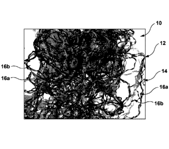
According to a broad aspect, and referring to Figures 1 and 2, there is
provided media 10 for
wastewater treatment on which bacteria can attach and grow. The media 10
comprises a plurality
of bundles 12 (also referred to as "clusters 12") of strands 14. Each bundle
12 has multiple strands
14. Within the media 10 there is intertwining between the strands 14 of each
bundle 12 ("intra-
bundle strand intertwining) as well as intertwining between at least some of
the strands 14 of the
strand bundles 12 ("inter-bundle strand intertwining). The media therefore
comprises media 10
having a tangled mass of strands 14 with spaces 16a, 16b in between for
wastewater to flow. Due
at least in part to the bundling of the strands 14, the spaces 16a between the
strands 14 of each
bundle 12 are generally smaller than the spaces 16b between strands 14 of
different bundles 12.
This can provide an improved fluid flow and hence contribute to treatment
efficiency, in certain
embodiments. The interconnectivity between the strands 14 within and between
the bundles 12
can also help to keep the media 10 together during installation and removal
from a reactor which
can make those processes more efficient. Furthermore, and with reference to
Example 1 below, it
was demonstrated that clustering strands 14 as bundles 12 in the media 10
significantly increases
an average break strength, compared to media comprising non-bundled strands of
equivalent mass.
An isolated bundle 12 of the strands 14 from the media 10 of Figures 1 and 2
is shown in Figure
3, and an isolated strand 14 from a bundle 12 is shown in Figure 4.
As best seen in Figure 3, the bundle 12 of strands 14 comprises three strands
14 intertwined with
one another. There are at least two strands 14 in a bundle 12, but the number
of strands 14 is not
particularly limited. For example, there may be provided two strands 14, three
strands 14, four
strands 14 or five strands 14 in the bundle 12. In certain embodiments, the
media 10 comprises
bundles 12 of strands 14 having the same number of strands 14. In other
embodiments, the media
10 comprises bundles 12 of strands 14 having different number of strands 14.
11
12073763.1
Date Recue/Date Received 2023-05-09
Referring now to Figures 3 to 5, each strand 14 of the bundle 12 comprises an
elongate undulating
(wavy) strip with surfaces on which bacteria can grow. As best seen in Figures
5 and 7, the surfaces
include a first surface 18, a second surface 20, a third surface 22 and a
fourth surface 24. It will be
appreciated that the strand 14 is ribbon-like, with a width of the surfaces
18, 20 being wider than
a width of the third and fourth surfaces 22, 24. The third and fourth surfaces
22, 24 are also referred
to herein as side edges 22, 24. The first and second surfaces 18, 20 are
oppositely facing one
another, and the third and fourth surfaces 22, 24 are oppositely facing one
another and substantially
transverse to the first and second surfaces 18, 20.
Referring to Figures 3, 4 and 5, each strand 14 is discrete, i.e. not
permanently fixed to another
strand, and has two free ends. In certain embodiments, a length of one of the
side edges 22, 24 is
longer than a length of the other of the side edges 22, 24 as a result of, or
giving rise to the
undulations.
Each strand 14 has undulations 26 along its length. The undulations 26 are
spaced from one
another, in series, along each strand 14. In certain embodiments, the
undulations 26 are spaced at
regular intervals from one another. In other embodiments, the undulations 26
are irregularly
spaced. A given strand 14 may also have some undulations 26 which are
regularly spaced and
other undulations 26 which are irregularly spaced.
A number of undulations 26 on each strand 14 is not particularly limited and
is dependent on the
length of the strand. In certain embodiments, there are more than about 50,000
undulations, more
than about 60,000 undulations, more than about 70,000 undulations, or more
than about 80,000
undulations on a given strand 14. In certain embodiments, there are about
85,000 undulations per
strand 14.
The undulations 26 of each strand 14 comprise convex undulations 26a as well
as concave
undulations 26b visible as peaks and troughs 26a, 26b, respectively. The
convex and concave
undulations 26a, 26b are also referred to as positive and negative waves 26a,
26b. In certain
embodiments, the convex and concave undulations 26a, 26b are alternated along
the length of the
12
12073763.1
Date Recue/Date Received 2023-05-09
strand 14. In other embodiments, the undulations 26 comprise concave
undulations 26a only, or
concave undulations 26b only.
A spacing of the undulations 26 from each other is not particularly limited.
In certain embodiments,
the spacing (best seen in Figure 5) of the undulations 26b-26b is between
about 2 and 3 cm, for
example 2.5 cm.
As best seen in Figure 6, which is an example top plan view of a single strand
14, the undulations
26 provide each strand 14 with an overall irregular configuration. Each strand
14 is non-planar in
3D space. In other words, each strand 14 has a configuration which bends and
twists in different
directions along its length. The two free ends of each strand 14 do not lie on
a same plane. It has
been found by the Developers that this configuration can help with the
intertwining between the
strands 14 of a given bundle 12.
Referring now to the intertwining between the strands 14 of each bundle 12,
the intertwining
comprises a criss-crossing of two or more of the strands 14 in each bundle 12.
In some
embodiments, the intertwining resembles helical entanglements, such as of the
type seen in DNA
strands. In other embodiments, the intertwining is less ordered and comprises
a criss-crossing or
a twisting between strands 14 at one or more locations.
The intra-bundle strand intertwining is different than the inter-bundle strand
intertwining.
Generally, the intra-bundle strand intertwining makes the strands 14 within
the respective bundle
12 harder to separate from each other than strands 14 between the bundles 12.
The intra-bundle
strand intertwining comprises a twisting together of some of the strands 14 of
some of the bundles
12. Not all the bundles 12 are interconnected with all other bundles 12. In
contrast, each strand 14
of each bundle 12 is interconnected with the other strands 14 of the given
bundle 12 in inter-bundle
strand intertwining. As best seen in Figure 3, in each bundle 12, the strands
14 may have numerous
points of criss-crossing 28 along the length of the respective strands.
The media 10 is made from a polymeric material such as acrylonitrile butadiene
styrene (ABS),
polyvinyl chloride (PVC), high-density polyethylene, polypropylene or any
other polymer that can
13
12073763.1
Date Recue/Date Received 2023-05-09
be heated, extruded, molded, milled, cast and/or made in a way that will allow
forming strands
with the undulations. The strand 14 is made of a material having a density of
within the range: 0.9-
1.55 g cm-3.
In certain embodiments, a length of each strand 14 is at least 400 m. In
certain embodiments, the
length of each strand 14 is about 500 m, about 600 m, about 700 m, about 800
m, about 900 m,
about 1000 m, about 1200 m, about 1400 m, about 1600 m, about 1800 m, about
2000 m. In certain
embodiments, the media 10 comprises bundles 12 of strands 14 having the same
length. In other
embodiments, the media 10 comprises bundles 12 of strands 14 having different
lengths. As
mentioned earlier, the two edges 22, 24 of a given strand 14 have different
lengths. These are true
lengths. The length of the strand 14 is a measure of the distance between the
two free ends when
taken at a mid point between the two edges 22, 24, and when the strand 14 is
at rest on a support
surface.
Referring to Figure 7, each strand 14 has a transverse cross-sectional shape
which is rectangular.
Although not illustrated, other transverse cross-sectional shapes are also
within the scope of the
present technology such as circular, square, trapezoidal, oval. Although the
surfaces 18, 20, 22, 24
are depicted as being flat, they may also have other configurations such as
discontinuous, porous,
indented, patterned, and the like.
In certain embodiments, a width 30 of each strand 14 is at least 3.5 mm. In
certain embodiments,
the width 30 of each strand 14 is about 4.0 mm, about 4.5 mm, or about 5.0 mm.
In certain
embodiments, the media 10 comprises bundles 12 of strands 14 having the same
width 30. In other
embodiments, the media 10 comprises bundles 12 of strands 14 having different
widths 30.
In the illustrated embodiment, a thickness 32 of the strand 14 is
substantially constant along its
length. However, in other embodiments, the thickness 32 may be variable. For
example, the strand
14 may be thinner at a peak and trough of a respective undulation 26. The
width 30 of the strand
14 is greater than the thickness 32 of the strand 14.
14
12073763.1
Date Recue/Date Received 2023-05-09
In certain embodiments, the thickness 32 of each strand 14 is at least 0.2 mm.
In certain
embodiments, the thickness 32 of each strand is about 0.2 mm, about 0.3 mm,
about 0.4 mm, or
about 0.5 mm. In certain embodiments, the media 10 comprises bundles 12 of
strands 14 having
the same thickness 32. In other embodiments, the media 10 comprises bundles 12
of strands 14
having different thicknesses 32. The width 30 of a given strand 14 is greater
than the thickness 32
of the given strand 14.
In certain embodiments, a ratio of the width 30 to the thickness 32 of the
strand 14 is 10, 15 or 20.
In embodiments where the ratio is 20, the strand 14 may have any one of the
respective width 30
.. and thicknesses 32: about 4 mm width and about 0.2 mm thickness; about 5 mm
width and about
0.25 mm thickness, and about 6 mm width and about 0.3 mm thickness. The ratio
of the width:
thickness of each strand 14 reflects its ribbon-like nature and exploits a
surface area: mass ratio
which is advantageous for supporting bacterial growth.
.. In certain embodiments, a transverse cross-section area of each strand 14
is about 0.8 mm2 or about
1.6 mm2.
Developers have also discovered that adapting various dimensions of the
strands 14 making up the
media can provide the media 10 with overall differing properties. These
dimensional relationships
are seen in both bundled configuration media 10 and non-bundled configuration
media of the
strand type. For example, Developers have discovered that doubling the
thickness 32 of the strand
14 whilst maintaining a specific surface area of the media 10, more than
doubles a resistance of
the media 10 to compressibility (Example 3). Increasing the thickness 32 also
improves the break
strength of the strands 14 (Example 4).
According to other aspects of the present technology, and referring to Figures
8 and 9, there is
provided reactors 100 housing the media 10 therein. The reactor 100 comprises
an inlet 110 and
an outlet 120.The media 10 distributes itself within wastewater 130 in the
reactor 100 so that it is
generally evenly distributed throughout the wastewater 130.
The media 10 can be provided at any suitable density relative to the volume of
the wastewater 130.
12073763.1
Date Recue/Date Received 2023-05-09
An amount of the media 10 in the wastewater 130 may be more than 80 m2 / m3 of
wastewater. In
certain embodiments, the surface area of the media 10 per volume of wastewater
comprises 80 m2
/ m3 to 330 m2 / m3. In certain embodiments, the media 10 comprises 165 m2
surface area of media
per m3 of wastewater. In certain embodiments, the media 10 occupies a volume
in one reactor of
about 1.0 % up to 5.0 %, between about 1.0% to about 3.0%, between about 1.3%
and 4%, or
between about 1.5% and about 3.5%.
In certain embodiments, such as the reactor 100 shown in Figure 9, the media
10 may be provided
in porous bags 150 which are removably attached to each other and/or the
reactor 100. The reactor
may comprise any configuration such as the reactor described in US 10,570,040
B2, the contents
of which are herein incorporated by reference.
The following examples are illustrative of the wide range of applicability of
the present technology
and is not intended to limit its scope. Modifications and variations can be
made therein without
departing from the spirit and scope of the invention.
EXAMPLES
Example 1: Media comprising bundles of strands vs. no bundles
Media 10 comprising bundles 12 of strands 14 with intra-bundle and inter-
bundle intertwining
according to embodiments of the present technology was compared with media
comprising
plurality of strands without the bundles. It was found that the media 10
comprising the bundles 12
of the strands 14 has improved properties over media comprising single
strands, as demonstrated
below. Each strand had the same thickness (0.2 mm) and width (4 mm).
Single strands Bundles of strands
(three strands per strand
bundle)
Compressibility (%) 34.50 34.50
Average break strength (N) 17.64 59.83
16
12073763.1
Date Recue/Date Received 2023-05-09
The media comprising bundles of strands has a higher average break strength
than media
comprising single strands. Compressibility is not compromised.
Example 2: Adjusting strand thickness (0.2 mm vs 0.4 mm thick strands) in
bundles
Media 10 comprising the bundles 12 of the strands 14 having thicknesses of 0.2
mm and 0.4 mm,
according to embodiments of the present technology, were compared. It was
found that the media
having thicker strands (0.4 mm) has improved average break strength over media
having less
thick strands (0.2 mm).
Media comprising strand bundles (three strands per strand bundle)
Each strand: 4 mm wide x Each strand: 4 mm wide x
0.2 mm thick 0.4 mm thick
Average break strength (N) 59.83 85.41
Compressibility is improved in the bundles when thickness of each strand is
increased. Average
10 break strength is improved when thickness of each strand in a bundle is
increased.
Example 3: Strand bundles, maintaining specific surface area and increasing
thickness of
each strand
Media 10 comprising the bundles 12 of the strands 14 having thicknesses of 0.2
mm and 0.4 mm,
according to embodiments of the present technology, were compared. It was
found that the
media 10 having thicker strands (0.4 mm) had significantly improved
compressibility (when
comparing equivalent specific surface areas of media, with the mass of the 0.4
mm thick media
having a mass which is about double the mass of the 0.2 mm thick media).
Media comprising strand bundles (three strands per strand bundle)
Each strand: 4 mm wide x Each strand: 4 mm wide x
0.2 mm thick 0.4 mm thick
Compressibility (%) (Specific 35.71 14.10
surface area is the same for both
groups)
17
12073763.1
Date Recue/Date Received 2023-05-09
Example 4: Single strands, 0.2 mm vs 0.4 mm thick strands
Single strands 14 having thicknesses of 0.2 mm and 0.4 mm were compared. It
was found that
the media 10 having thicker strands (0.4 mm) had significantly improved
average break strength
compared to the thinner strands.
Single strand
Each strand: 4 mm wide x Each strand: 4 mm wide x
0.2 mm thick, ABS 0.4 mm thick, ABS
Average break strength (N) 17.64 36.24
Example 5: Compressibility test
A container having internal dimensions of 711 mm x 711 mm x 711 mm was
obtained. The
given volume of the container represents a specified volume that the media 10
would occupy in a
reactor. The container comprised a cover that can move up and down using a
vertical guiding
rail. To test for compressibility of the media, the media was placed inside
the container and the
cover was placed on top. Load was applied to the lid to compress the media
(25.4 kg). A height
of the cover from a base of the container was measured before and after the
application of the
load.
Example 6: Average break strength
A strand of the media is held securely by two jaws. One jaw is moved away from
the other jaw
until breaking point. The force required to break the strand is measured.
The media, method of use and wastewater treatments in which it is used can be
applied to treating
wastewater discharged from residential, commercial or community wastewater
systems, as well as
any liquid containing impurities in the present or in any other technical
fields, such as industrial
or agri-food wastewater. For this reason, "wastewater", should not be taken to
limit the scope of
the present invention and should be taken to include all other kinds of
liquids or technical
18
12073763.1
Date Recue/Date Received 2023-05-09
applications with which the present invention may be used and could be useful.
Furthermore, the
reactor of the present disclosure is not limited to use within a reactor as
described in relation to
Figures 8 and 9. Embodiments of the media of the present disclosure can be
used in any suitable
water treatment chain, system or method.
Variations and modifications will occur to those of skill in the art after
reviewing this disclosure.
The disclosed features may be implemented, in any combination and
subcombinations (including
multiple dependent combinations and subcombinations), with one or more other
features described
herein. The various features described or illustrated above, including any
components thereof,
may be combined or integrated in other systems. Moreover, certain features may
be omitted or not
implemented. Examples of changes, substitutions, and alterations are
ascertainable by one skilled
in the art and could be made without departing from the scope of the
information disclosed herein.
For example, it will be appreciated that the media can be used in any other
suitable wastewater
treatment reactor or system. All references cited herein are incorporated by
reference in their
entirety and made part of this application.
It should be appreciated that the invention is not limited to the particular
embodiments described
and illustrated herein but includes all modifications and variations falling
within the scope of the
invention as defined in the appended claims.
19
12073763.1
Date Recue/Date Received 2023-05-09