Note: Descriptions are shown in the official language in which they were submitted.
CA 03179669 2022-09-30
WO 2022/214878
PCT/IB2022/000209
1
ENERGY ALLOCATION AND MANAGEMENT SYSTEM
CROSS REFERENCE TO RELATED APPLICATIONS
[1] This application claims the benefit of priority to U.S. Provisional
Application No. 63/201,
061, filed April 9, 2021. This provisional application is incorporated herein
by reference in its
entirety.
BACKGROUND
[2] Traditional electrical power systems can operate using large, centralized
power generation
resources and unidirectional power flow to the loads. The transmission and
distribution
networks appear as infinite energy resources to the loads. With the
proliferation of distributed
generation resources, the power flow has become bidirectional. Furthermore,
those renewable
resources are intermittent in nature and require the use of distributed energy
storage resources
to keep the system stable and controllable.
[3] Despite the advantages of centralized control for optimization and
monitoring,
decentralized control of distributed resources is a preferred control
principle as it gives
scalability and flexibility to the installations without the need for
expensive and time-
consuming reconfiguration. Common operation principles and implementation
techniques are
usable in diverse decentralized systems. On the other hand, each centralized
system needs to
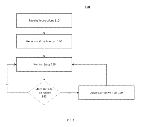
be specific and custom designed. Microgrids where multiple resources and loads
are
operating simultaneously can introduce additional challenges to the management
of energy
storage resources. These challenges can be accentuated when the energy storage
is used to
power balance the system.
[4] Energy storage can be used in many different applications. The strategy
used to manage
the energy storage depends on the specific application. For example, in backup
applications,
the storage can be maintained fully charged until an event necessitating
discharge occurs. In
electric vehicles (EVs), the battery can be charged while the loads are idle
and then managed
CA 03179669 2022-09-30
WO 2022/214878
PCT/IB2022/000209
2
to handle acceleration and braking while estimating the remaining driving
range. In solar
plus storage applications, the storage can be managed to ensure maximum solar
energy
storage during the sun hours to level or shift the production as needed.
SUMMARY
[5] The disclosed systems and methods concern the control of energy dispatch
and energy
allocation.
[6] The envisioned embodiments include a controller for managing power
transfer in a
distributed power transmission system. The controller can include at least one
processor and
at least one memory storing instructions. When executed by the at least one
processor, the
instructions can cause the controller to perform operations. The operations
can include
receiving a forecast trajectory for a power node; determining a measured
trajectory for the
power node; determining an error signal using the forecast trajectory and the
measured
trajectory; and providing instructions to reduce the error signal. The
instructions can be
provided to at least one smart interface controller to transfer energy between
the power node
and at least one power system connected to the power node. The instructions
can cause
energy to be transferred between the power node and an energy storage device
connected to
the power node.
[7] The envisioned embodiments include a controller for managing energy
allocation in a
distributed power transmission system. The controller can include at least one
processor; and
at least one memory storing instructions. When executed by the at least one
processor, the
instructions can cause the controller to perform operations. The operations
can include
receiving tasks and corresponding priorities for a power node; and for an
interval: iteratively
in priority order for each task: determine an energy requirement amount for
the task; and
when the energy requirement amount is less than an available energy amount:
allocate the
energy requirement amount to the task; and update the available energy amount
based on a
CA 03179669 2022-09-30
WO 2022/214878
PCT/IB2022/000209
3
total available energy amount and the energy requirement amount. The
operations can
include providing instructions to a smart interface controller to transfer
power between the
power node and at least one power system connected to the power node, based on
a first
energy requirement amount allocated to a first task of ensuring an energy
supply to loads
connected to the power node. The instructions can cause energy to be
transferred between the
power node and an energy storage device connected to the power node, based on
a second
energy requirement amount allocated to a second task of maintaining the energy
storage
device on a stored energy trajectory.
[8] The disclosed embodiments include a controller for a power system. The
controller can
include at least one processor and at least one memory storing instructions
that, when
executed by the at least one processor, cause the controller to perform
operations for
correcting a state of a first node of the power system. The operations can
include obtaining
rules for correcting the state of the first node, each rule specifying a
corrective action for the
first node. The operations can further include obtaining instructions for the
first node, the
instructions at least partially specifying a configuration of the first node.
The operations can
further include generating a forecast for the state of the first node based on
the instructions
The operations can further include monitoring the state of the first node.
Based on the
forecast state and the monitored state of the first node, the controller can
select one of the
rules and apply the corrective action specified by the selected rule to
correct the state of the
first node.
[9] The disclosed embodiments include a method for correcting a state of a
node of a power
system. The methods can include obtaining rules for correcting the state of
the first node,
each rule specifying a corrective action for the first node; obtaining
instructions for the first
node, the instructions at least partially specifying a configuration of the
first node; generating
a forecast for the state of the first node based on the instructions; and
monitoring the state of
CA 03179669 2022-09-30
WO 2022/214878
PCT/IB2022/000209
4
the first node. Based on the forecast state and the monitored state of the
first node, once of the
rules can be selected and the corrective action specified by the selected rule
applied to correct
the state of the first node.
[10] The disclosed embodiments include a controller for a node in a power
system. The
controller can include at least one processor and at least one memory storing
instructions that,
when executed by the at least one processor, cause a controller of the node to
perform
operations. The operations can include obtaining functions and corresponding
priorities. The
operations can include allocating, in an energy storage device of the node,
time-dependent
energy storage capacities for the functions based on the priorities. Such
allocating can include
selecting a function based on the corresponding priorities; selecting a time
interval;
determining an energy requirement amount for the selected function in the
selected time
interval; and determining that the energy requirement amount is less than an
available energy
capacity of the energy storage device and, in response to the determination,
allocating an
amount of available energy capacity in the energy storage device to
performance of the
function during the interval. The operations can include determining, in
response to a request
to perform a first function, an amount of power transferable from the energy
storage device
based on the time-dependent energy storage capacity for the first function.
The operations can
include providing instructions to configure the node to transfer the
determined amount of
power from the energy storage device.
[11] The disclosed embodiments include a method performed by a controller of a
node for
allocating power in an energy storage device of a node. The method can include
obtaining
functions and corresponding priorities. The method can include allocating, in
the energy
storage device, time-dependent energy storage capacities for the functions
based on the
priorities. Such allocation can include selecting a function based on the
corresponding
priorities; selecting a time interval; determining an energy requirement
amount for the
CA 03179669 2022-09-30
WO 2022/214878
PCT/IB2022/000209
selected function in the selected time interval; and determining that the
energy requirement
amount is less than an available energy capacity of the energy storage device
and, in response
to the determination, allocating an amount of available energy capacity in the
energy storage
device to performance of the function during the interval. The method can
include
determining, in response to a request to perform a first function, an amount
of power
transferable from the energy storage device based on the time-dependent energy
storage
capacity for the first function. The method can include providing instructions
to configure the
node to transfer the determined amount of power from the energy storage
device.
[12] It is to be understood that both the foregoing general description and
the following
detailed description are exemplary and explanatory only and are not
restrictive of the
disclosed embodiments, as claimed.
BRIEF DESCRIPTION OF THE DRAWINGS
[13] The drawings are not necessarily to scale or exhaustive. Instead,
emphasis is generally
placed upon illustrating the principles of the embodiments described herein.
The
accompanying drawings, which are incorporated in and constitute a part of this
specification,
illustrate several embodiments consistent with the disclosure and, together
with the
description, serve to explain the principles of the disclosure. In the
drawings:
[14] FIG. 1 depicts a method for updating system operation using an energy
dispatch plan, in
accordance with disclosed embodiments.
[15] FIG. 2 depicts an exemplary node including energy generation and storage
resources, in
accordance with disclosed embodiments.
[16] FIG. 3 depicts a hypothetical example of real time adjustment, in
accordance with
disclosed embodiments.
[17] FIG. 4 depicts a hypothetical example of real time adjustment in which a
load
continuously differs from an energy dispatch plan, in accordance with
disclosed
CA 03179669 2022-09-30
WO 2022/214878
PCT/IB2022/000209
6
embodiments.
[18] FIG. 5 depicts an exemplary method for allocating stored energy,
consistent with
disclosed embodiments.
[19] FIG. 6 depicts an exemplary energy allocation between functions over
time, in
accordance with disclosed embodiments.
[20] FIG. 7 depicts an exemplary energy allocation between functions over
time, given a
request from the grid to provide 3 hours of support starting at a first time
interval, in
accordance with disclosed embodiments.
[21] FIG. 8 depicts an exemplary energy allocation between functions over
time, given a
request from the grid to provide 3 hours of support starting at a second time
interval, in
accordance with disclosed embodiments.
DETAILED DESCRIPTION
[22] Reference will now be made in detail to exemplary embodiments, discussed
with regards
to the accompanying drawings. In some instances, the same reference numbers
will be used
throughout the drawings and the following description to refer to the same or
like parts.
Unless otherwise defined, technical and/or scientific terms have the meaning
commonly
understood by one of ordinary skill in the art. The disclosed embodiments are
described in
sufficient detail to enable those skilled in the art to practice the disclosed
embodiments. It is
to be understood that other embodiments may be utilized and that changes may
be made
without departing from the scope of the disclosed embodiments. For example,
unless
otherwise indicated, method steps disclosed in the figures can be rearranged,
combined, or
divided without departing from the envisioned embodiments. Similarly,
additional steps may
be added, or steps may be removed without departing from the envisioned
embodiments.
Thus the materials, methods, and examples are illustrative only and are not
intended to be
necessarily limiting.
CA 03179669 2022-09-30
WO 2022/214878
PCT/IB2022/000209
7
[23] ENERGY DISPATCH PLANNING
[24] Conventional methods for dispatching power systems that integrate
multiple resources
including renewable energy and energy storage systems can rely on generation
and load
forecast to make decisions regarding the appropriate operation of the
resources. Deviations
between the actual generation and load and the forecasted values can result in
unsuitable
operations or require frequent adjustments to planned operations. In
decentralized systems,
operation planning can be executed by a high-level control system and then
communicated to
the decentralized nodes, or can be executed in the distributed nodes based on
system data
communicated from central servers. Frequent recalculation of the operation
plan pushes the
control approach away from plug-and-play decentralized control.
[25] Consistent with disclosed embodiments, nodes in a power system can
compensate for
deviations from a forecasted state, without requiring recalculation of an
overall dispatch plan
for the power system or communication between nodes in the power system. State
variables
for a node can be monitored, to identify deviations from planned values. The
state variables
can be selected such that deviations can be identified before the node has
drifted too far from
planned operations. For example, in some embodiments the nodes can include
energy
storage. This energy storage can be used to compensate for changes in
renewable generation
or load consumption. Monitored state variables can include operating
conditions of the
energy storage (e.g., battery power, state of charge, battery temperature, or
the like).
[26] The disclosed embodiments can be suitable for decentralized control of
nodes in a power
system and can be executed independently for each node of the power system.
Consistent
with disclosed embodiments, nodes in a power system can identify and react to
deviations in
monitored state variables independently of other nodes in the power system and
without the
need for fast and reliable communication.
[27] Accordingly, the disclosed embodiments can enhance the decentralized
operation of the
CA 03179669 2022-09-30
WO 2022/214878
PCT/IB2022/000209
8
power system. The disclosed embodiments can increase the reliability,
scalability, and
flexibility of the decentralized system, while supporting the satisfaction of
overall power
system performance requirements, despite uncertainty in forecasted states.
Furthermore, the
disclosed embodiments can enable efficient use of distributed energy resources
(e.g.,
generation or storage) and thereby reduce project equipment and design
requirements.
[28] DISPATCH CORRECTION
[29] Consistent with disclosed embodiments, a power-system-level dispatch plan
can be
generated based on an overall forecast of power generation and use for the
power system.
Instructions for implementing this plan can be distributed to nodes in the
power system. The
nodes in the power system can execute these instructions, thereby implementing
the dispatch
plan. Real-time communication capabilities between nodes in the power system
are not
required as the dispatch plan is generated in advance. The instructions to
implement the plan
can be distributed to nodes using low-bandwidth or low-cost networks. For
example, power
line communication methods can be used to transmit such instructions. As an
additional
example, instructions can be distributed when bandwidth is readily available
(e.g., at night)
for subsequent use (e.g., the next day).
[30] The nodes in the power system can configure internal resources (e.g.,
generation
sources, energy storage source, power connections between the node and other
nodes)
according to the instructions to implement the dispatch plan. Consistent with
disclosed
embodiments, a node can generate a forecast of the state of the node over an
interval (e.g., a
trajectory of the state) based on expected operating conditions during that
interval. For
example, the dispatch plan can specify the power a local node can expect to
receive from a
community node over a 24-hour interval. The local node can then forecast a
trajectory of the
state based on the estimated power received and other factors (e.g.,
historical power
generation from distributed power generation sources attached to the node,
historical power
CA 03179669 2022-09-30
WO 2022/214878
PCT/IB2022/000209
9
usage from loads attached to the node, or the like). As described herein, the
state can include
a status or configuration of the node. For example, when the node includes an
energy storage
device, the state of the node can include status information of the energy
storage device (e.g.,
state of charge, temperature, average or instantaneous power transfer, or the
like). Likewise,
when the node includes power connections to another node, a main power source
(e.g., a
power grid), or a secondary power source (e.g., an intermittent power source
such as a solar
array, wind turbine, or other renewable energy source), the state of the node
can include the
configuration of these power connections (e.g., the specified and/or actual
amount and
direction of average or instantaneous power transfer). Similarly, when the
node is associated
with loads, the state can include the average or instantaneous power
requirements of each
load (or all loads). In some embodiments, when the node can be configured to
disconnect
power sources or loads from the node, the state can include whether the power
sources or
loads are connected or disconnected.
1311 Consistent with disclosed embodiments, during the interval, the node can
compare the
actual state of the node to the forecasted state of the node. The actual state
of the node can be
obtained from measurement data. This data can be obtained in real time from
sensors
associated with the node. If the actual state of the node begins to differ
from the forecasted
state of the node, the node can immediately detect the deviation. The node can
then
automatically execute corrections to the configuration of the internal
resources of the node to
adjust the state of the node back to the forecasted state. Accordingly,
corrections to the
configuration of the node can be implemented before any major deviation in
energy
availability, energy utilization, or system performance is observed.
Furthermore, the
corrections can be locally executed by the decentralized node without the need
to
communicate with any higher-level control node or recalculate the system-level
dispatch
plan.
CA 03179669 2022-09-30
WO 2022/214878
PCT/IB2022/000209
[32] Consistent with disclosed embodiments, the node can be configured with
rules for
automatically reconfiguring the internal resources of the node to return the
state of the node
to the forecasted state. Such rules can specify how one or more of the
internal resources
should be reconfigured to correct deviations from the forecasted state. For
example, the
renewable generation and load demand can be forecasted based on environmental
data and
past performance. Using the forecasted data, a controller executes an
optimization algorithm
that results in power dispatch actions. However, the forecast data is always
susceptible to
errors due to climatic and operating conditions that cannot be anticipated.
[33] In some embodiments, the optimization produces, amongst other data, a
time plot for the
expected energy storage power and the expected energy storage state of charge.
The storage
power and state of charge during operation are measured and compared with the
optimization
data. If the storage power is above the expected value by a predetermined
amplitude and
duration, the system will react by changing the power dispatched by some of
the components
so that the power is recovered to a value closer to the optimization data.
Accordingly, the
node can monitor the state of the node and apply rules as necessary to correct
deviations from
the forecast state.
[34] FIG. 1 depicts a method 100 for updating system operation. Consistent
with disclosed
embodiments, method 100 can be implemented by a node comprising a controller,
an energy
storage source, one or more loads, and one or more power connections. Such
power
connections can connect the node with another node or with a power source.
Such power
sources can be or include intermittent power sources (e.g., peaking plants;
grid-level energy
storage; or solar power sources, wind power sources, tidal power sources, or
other renewable
power sources). For example, a local node can have two power connections. A
first power
connection can connect the local node to a community node that acts as a main
energy source
for the local node. A second power connection can connect the local power to a
renewable
CA 03179669 2022-09-30
WO 2022/214878
PCT/IB2022/000209
11
energy source that provides intermittent power to the local node. An example
of such an
arrangement is described below with respect to FIG. 2.
[35] In step 110 of method 100, the local node can receive instructions. The
instructions can
be received from another node (e.g., a community node), a power source, or a
high-level
controller (e.g., a controller associated with the overall power system of
which the local node
may be a component), or a similar component of the power system.
[36] The instructions can enable the node to implement an intended role within
a dispatch
plan associated with the power system of which the node is a component. In
general, the
dispatch plan may be designed to reduce costs associated with the overall
power system (e.g.,
generation costs, distribution costs, maintenance costs, or the like), shift
power generation
from one source to another (e.g., from fossil fuel generation to renewable
generation),
improve system reliability (e.g., fill local energy storage in advance of a
heat wave that is
anticipated to strain power generation and distribution capabilities), or
otherwise improve the
functioning of the power system.
[37] In some embodiments, the instructions can at least partially specify a
configuration of
the node. Such a configuration can include power exchanges, load maintenance
or shedding,
energy storage levels, or other aspects of the node. For example, the
instructions can specify
power exchanges over the power connection(s) of the node. These power
exchanges can be
specified as a function of time. For example, a node can receive instructions
to draw, over a
connection with a community node, 4 kW between 12:00 AM and 6:00 AM, 1 kW
between
6:00 AM and 8:00 PM, and 4 kW between 8:00 PM and 11:59 PM. Such power
exchanges
can be specified in terms of current (e.g., amperes), potential (e.g.,
voltage), power (e.g.,
watts), energy (e.g., joules or kilowatt-hours), or another suitable metric.
[38] The disclosed embodiments are not limited to any particular transmission
modality or
format for the instructions. In some embodiments, the instructions can be
transmitted over a
CA 03179669 2022-09-30
WO 2022/214878
PCT/IB2022/000209
12
power connection (e.g., using an AC or DC power-line communication modality).
In various
embodiments, the instructions can be transmitted through a different channel
than the power
received by the node. For example, the instructions can be received through a
wired (e.g.,
coaxial cable, phone line, network cable, or similar suitable connections) or
wireless (e.g.,
cellular, WIFI, BLUETOOTH, ZIGBEE, infrared, radio, or similar suitable
connections)
channel. In some embodiments, the instructions can be implemented using a data-
interchange
format, such as XML, JSON, or the like.
[39] In step 120, the node can be configured to generate a forecast of a state
of the node. In
some embodiments, as described herein, the state of the node can include
variables describing
a status of the node or components thereof (e.g., an amount of stored energy
of the node)
and/or variables describing the node configuration (e.g., battery temperature
or discharge
rate; internal bus voltage or current; average or instantaneous power usage or
net power
usage; current or power drawn exchange with other nodes, or other suitable
information). The
forecast can be a trajectory of the node in a state space.
[40] The node can generate the forecast of the state of the node based on the
received
instructions and other information. The other information can concern factors
that potentially
affect the configuration of the node. For example, the other information can
include historical
load information, environmental information (e.g., temperature, precipitation,
cloudiness,
wind speed and direction, or other factors that might affect energy demand or
energy
production). The other information can be historical, current, or prospective.
For example, the
other information can include historical records of energy usage for a day of
the year. As an
additional example, the other information can include weather forecasts.
[41] Consistent with disclosed embodiments, the other information can be
obtained by the
node. The node can receive or retrieve the other information from an external
source (e.g.,
weather information could be obtained from a website using an API exposed by
that website,
CA 03179669 2022-09-30
WO 2022/214878
PCT/IB2022/000209
13
or a high-level controller associated with the power system could provide the
weather
information to the node). The node can generate the other information (e.g.,
by accumulating
measurements of power consumption over time). The node can obtain the
information using
the same channel as the instructions received in step 110, or another such
channel.
[42] To continue a previous example, a local node can receive instructions to
configure a
power connection between the local node and a community node to request 4 kW
between
12:00 AM and 6:00 AM, 1 kW between 6:00 AM and 8:00 PM, and 4 kW between 8:00
PM
and 11:59 PM. Thus the node can obtain 54 kilowatt hours of energy over the
course of the
day from the community node. Based on historical energy usage, the node can
forecast a load
of 0.5 kW between 12:00 AM and 9:00 AM, a load of 7 kW between 9:00 AM and
5:00 PM
and a load of 0.5 kW between 5:00 PM and 11:59 PM. Thus the node can expect
usage of 64
kilowatt hours over the course of the day. To accommodate the expected
shortfall of 10
kilowatt hours, the node can configure itself to obtain energy from another
source (e.g., a
renewable energy source) or to deplete energy storage by an energy storage
device of the
node. The node can configure obtaining energy from the other source or
depleting the energy
storage of the node according to performance criteria of the node. Assuming,
in this example,
that the state of the node includes the power received (or sent) to the
community node, the
power received from the other power source, the load, and the state of charge,
the node can
generate a forecast of these variables over the next 24 hours. This forecast
can then be used to
determine whether corrections must be applied to return the node to its
intended operation
conditions.
[43] In step 130 of method 100, the node can be configured to monitor the
state of the node.
This monitoring can be performed using sensors that provide data accessible to
the node. For
example, a controller of the node can receive sensor data describing the
status of an energy
storage device of the node (e.g., a state of charge of a battery, or
temperature of the battery),
CA 03179669 2022-09-30
WO 2022/214878
PCT/IB2022/000209
14
current drawn by loads attached to the node, current supplied by the community
node, or the
like. In some embodiments, the node can be configured to determine an actual
trajectory of
the state of the node in a state space.
[44] In step 140 of method 100, the node can determine whether the state of
the node is
outside a tolerance range. Consistent with disclosed embodiments, method 100
can transition
from step 130 to step 140 repeatedly, periodically, or according to some
schedule.
[45] This determination can depend on a single variable in the state (e.g., a
state of change of
a battery of the node), a combination of variables in the state (e.g., a
battery temperature and
power drawn by loads attached to the node), or a comparison of the
trajectories of the
forecast and actual states of the node in the state space. The determination
can include
applying rules to the state of the node. In such implementations, satisfaction
of a rule (or
failure to satisfy a rule) can indicate that the state of the node is out of
tolerance. In some
embodiments, the rules can describe a tolerance range for the variables (or
combination of
variables). A tolerance range can be expressed in absolute terms (e.g., +/-
0.5 amps) or in
relative terms (e.g., +/- 5%). Tolerance ranges can be a function of time and
date. For
example, when a battery is recharged every night, a tolerance on the state of
change of the
battery can be higher in the evening than in the morning.
[46] In some embodiments, determination of whether a state with within a
tolerance can be
formulated as applying a deadband function to a difference between the
forecasted state
variable and the measured value of that state variable. In some embodiments, a
determination
that a variable is out of tolerance can depend on the trajectory of the
measured state variable,
or the trajectory of the difference between the measured and forecasted state
variable.
[47] In some embodiments, variables in the state of the node can be checked
according to a
hierarchy or precedence. When the node is designed to provide current at a
constant voltage
to loads attached to the node through a common bus, the voltage of the common
bus may be
CA 03179669 2022-09-30
WO 2022/214878
PCT/IB2022/000209
the first state variable checked. When the node is designed to maintain a
storage battery
between 20% and 80% charge, the state of charge of the battery may be the next
variable
checked. When an excessive rate of charging or discharging may overheat the
battery,
damaging it, the temperature of the battery may be the next variable checked.
[48] If the state is not out of tolerance, method 100 can return to monitoring
of the state of the
node in step 130. Otherwise, method 100 can transition to step 150.
[49] In step 150 of method 100, the node can apply a corrective rule,
consistent with
disclosed embodiments. Applying the corrective rule can include selecting the
corrective rule
to apply. In some embodiments, the node can be provisioned with corrective
rules specific to
each monitored state variable (or monitored combination of state variables).
For example, a
first rule may proscribe a corrective action for responding to a low state of
charge, while a
second rule may proscribe a corrective action for responding to greater than
expected current
demanded by loads. Thus the node can select the corrective rule to apply based
on the state
variable (or combination of state variables) that is out of tolerance.
[50] In some embodiments, the node can be provided with multiple rules for a
monitored
state variable. For example, a first rule for responding to a low state of
charge may be to
begin drawing power from a secondary power generation source attached to the
node (e.g., a
peaking plant, solar array, windmill, or the like). A second rule for
responding to a low state
of charge may be to begin load-shedding procedures. In such embodiments, the
node can
select the rule to apply based on the magnitude of the departure of the state
variable from the
tolerance or whether a rule was previously applied.
[51] For example, the node may be configured to initially apply a rule that
imposes a minor
corrective action (e.g., increasing power drawn from a community node, or the
like). Method
100 can then return to monitoring the node in step 130, and then transition to
determining
whether the node is in tolerance. If the state variable remains out of
tolerance, the node can
CA 03179669 2022-09-30
WO 2022/214878
PCT/IB2022/000209
16
apply another rule that imposes a more significant corrective action (e.g.,
load shedding, or
the like). Alternatively, when faced with a major shortfall in the state of
charge, the node can
immediately apply a rule that causes it to begin load shedding.
[52] In some instances, applying a corrective action can cause other state
variables to depart
from their forecasted values. For example, a local node may require additional
power from a
community node in response to a low state of charge. The additional power can
appear as a
deviation from the forecast amount of power obtained from the community node.
[53] In some embodiments, application of a rule may cause the node to adjust
tolerances of
other variables. For example, a rule that implemented a corrective action by
increasing power
obtained from another node could cause the tolerance for obtaining such power
to be
increased.
[54] In some embodiments, application of a rule may cause the node to re-
forecast the state of
the node. The updated forecast can incorporate the current state of the node
and the
consequences of the rules applied to the node.
[55] FIG. 2 depicts a system 200 for power distribution, consistent with
disclosed
embodiments. System 200 can include multiple nodes (e.g., community node 210
and local
node 223 of combined system 220) connected by power distribution buses (e.g.,
external bus
230 and internal bus 240) through smart interface controllers (e.g., smart
interface controller
221) to enable decentralized control of power distribution, while minimizing
the information
communicated between nodes.
[56] In some embodiments, the nodes of system 200 can be hierarchically
arranged. Nodes
with more generation or storage capabilities may provide power to nodes with
lesser
generation or storage capabilities. As a non-limiting example, a community
including
multiple residences can have a node associated with the community and a node
associated
with each of the residences. The node associated with the community can
include a
CA 03179669 2022-09-30
WO 2022/214878
PCT/IB2022/000209
17
generation source (e.g., a coal-fired powerplant) and a utility-scale energy
storage component
(e.g., megawatt-hour capacity batteries). The nodes associated with the
residences may or
may not include generation components (e.g., solar panels) and may have
smaller energy
storage components (e.g., kilowatt-hour capacity batteries). In this example,
the community
node may typically provide power to each of the residential nodes. But the
amount of power
provided may vary between residential nodes, and under some circumstances the
direction of
power transfer may reverse, with a residential node providing power to the
community node
(e.g., a residential node with substantial solar generation capabilities can
provide power to the
community node on a sunny day).
[57] Community node 210 can include an electrical power grid, a controller,
and optionally
energy storage component 215. In some embodiments, a single device can
include, or provide
the functionality of, optional energy storage component 215 and the
controller. In various
embodiments, separate devices can include, or provide the functionality of,
optional energy
storage component 215 and the controller. Community node 210 can include
generation
sources that provide power and loads that consume power. Community node 210
can be
connected to combined system 220 through external power bus 230. Community
node 210
can be configured to exchange power with combined system 220 using external
power bus
230.
[58] The electrical power grid can be configured to provide electrical current
at a voltage
amplitude (or within a voltage amplitude range). The electrical power grid can
be an
alternating current power grid or a direct current power grid. The disclosed
embodiments are
not limited to any particular topology or implementation of this power grid.
In some
embodiments, the electrical power grid in community node 210 can be or include
external
power bus 230.
[59] In embodiments including energy storage component 215, this component can
be
CA 03179669 2022-09-30
WO 2022/214878
PCT/IB2022/000209
18
configured to automatically provide or store power in order to maintain the
electric power
grid at a voltage amplitude or within a voltage amplitude range (e.g., voltage
amplitude can
be within -20% and + 10% of a nominal value). In some embodiments, energy
storage
component 215 can be configured to address changes in power generation
occurring on a
timescale of less than a second, less than a minute, or less than an hour.
[60] Optional energy storage component 215 can include at least one of an
electrical (e.g.
capacitive, or the like), electrochemical (e.g., battery or the like),
mechanical (e.g., flywheel,
compressed or liquid air, or the like), hydroelectric (e.g., pumped storage or
the like), or
similar energy storage system. In some embodiments, the storage component can
be
configured to sink or source direct current at a voltage. In some embodiments,
energy storage
component 215 can be directly connected to the power grid. For example, the
storage device
can be one or more batteries having terminals connected directly to the power
grid. In such
embodiments, a voltage of the electrical power grid can be automatically
maintained at a
setpoint determined by the energy storage component 215. For example, when the
terminals
of the one or more batteries are directly connected to the electrical power
grid, the voltage of
the electrical power grid can automatically depend on a state of charge of the
battery, without
requiring additional hardware or software. In various embodiments, the storage
component
can be indirectly connected to the power grid. For example, a converter (such
as a DC/DC
convertor or power inverter) can be placed between the energy storage
component and the
power grid. The converter can be configured to sink or source power from the
electrical
power grid as necessary to maintain a voltage of the electrical power grid at
a setpoint or
within a range (e.g., a predetermined setpoint or range).
[61] The controller (not shown) of community node 210 can be configured to
manage
community node 210 to maintain a state of community node 210 within a
tolerance (e.g., as
described herein with respect to FIG. 1). In some embodiments, the controller
can be
CA 03179669 2022-09-30
WO 2022/214878
PCT/IB2022/000209
19
configured to monitor variations in power generation and demand on a timescale
of a minute
to an hour, or an hour to a day, or multiple days.
[62] The controller can be configured to manage the community node 210 based
on
information concerning or affecting the past, present, or future state of
community node 210,
as described herein. In some embodiments, the controller can be configured to
receive this
information using one or more communications networks (e.g., a local area
network, wide
area network, mobile network, or the like). For example, the controller can be
connected to
other components of community node 210 over a local area network and to
external devices
over a mobile network or the internet.
[63] The controller of community node 210 can be configured to manage
community node
210 by modifying power generation, power usage, or power storage within
community node
210. The controller can modify power generation by adding or removing power
generation
sources to or from the power grid. For example, the controller can provide
instructions to
configure renewable power generation sources such as wind turbines or solar
panels to
contribute power to the power grid. As an additional example, the controller
can provide
instructions to start or stop generators connected to the power grid, such as
gas peaking plants
or other power plants. The controller can be configured to manage local power
use by
providing instructions to adjust power consumption by devices connected to the
electrical
power grid of community node 210. For example, the controller can modify power
usage by
providing instructions to shed loads or reschedule the actions of devices
connected to the
electrical power grid of community node 210. For example, the controller can
provide
instructions to turn off or reschedule operation of an air conditioning unit
or turn off external
lights on a dwelling. In some embodiments, the power generation components or
loads can
automatically implement the instructions provided by the controller. In
various embodiments,
the instructions can be implemented at least partially manually.
CA 03179669 2022-09-30
WO 2022/214878
PCT/IB2022/000209
[64] The controller of community node 210 can manage community node 210 by
requesting
power transfers with other nodes. For example, community node 210 can be
configured to
provide a request to transfer power between community node 210 and another
node. In some
embodiments, the controller can provide instructions to a smart interface
controller (e.g.,
smart interface controller 221). The smart interface controller can be
connected to community
node 210 by a power bus (e.g., external power bus 230) and connected to the
other node by
another power bus (e.g., internal power bus 240). Based on the instructions,
smart interface
controller 221 can transfer power between the community node and the other
node.
[65] External bus 230 can be configured to transfer power between the
community node 210
and the combined system 220. External bus 230 can be configured to transfer
direct current or
alternating current and is not limited to a particular voltage amplitude (or
frequency in
embodiments using alternating current). In some embodiments, external power
bus 230 can
be, or be part of, the electrical power grid of community node 210.
[66] In some embodiments, smart interface controllers can be included in nodes
of system
200. For example, as depicted in FIG. 2, combined system 220 can include local
node 223
and smart interface controller 221 (alternatively, a combined system could
include
community node 210 and smart controller 221, implemented as described herein).
Consistent
with disclosed embodiments, smart interface controller 221 can be configured
to manage
power transfers between community node 210 and local node 223.
[67] Similar to community node 210, local node 223 can include a controller,
an energy
storage component (e.g., energy storage component 225) and an electrical power
grid. In
some embodiments, energy storage component 225 may be optional. In some
embodiments, a
single device can include, or provide the functionality of, at least two of
the controller, energy
storage component 225, and smart interface controller 221. In various
embodiments, smart
interface controller 221 can be separate from local node 223 (e.g., smart
interface controller
CA 03179669 2022-09-30
WO 2022/214878
PCT/IB2022/000209
21
221 can be implemented on a device separate from the device(s) implementing
energy
storage component 225 and the controller of local node 223). When a smart
interface
controller is included in a node, communications described herein as being
sent to the smart
interface controller may, in some embodiments, be sent to the node including
the smart
interface controller. This node may then act on the received communications,
for example by
forwarding them to the smart interface controller or communicating with the
smart interface
controller in response to the received communications. In some embodiments,
smart interface
controller 221 and the controller of node 223 can be the same controller. In
such
embodiments, instructions exchanged between the controller of node 223 and
smart interface
controller 221 can be processed internally by the combined controller.
[68] The electrical power grid can be configured to provide electrical current
at a voltage
amplitude (or within a voltage amplitude range). The electrical power grid can
be an
alternating current power grid or a direct current power grid. The disclosed
embodiments are
not limited to any particular topology or implementation of this power grid.
In some
embodiments, the electrical power grid in local node 223 can be or include
internal power bus
240
[69] Energy storage component 225 can be similar in construction and operation
to energy
storage component 215. Energy storage component 225 can be configured to
automatically
provide or store power in order to maintain the electric power grid at a
voltage amplitude or
within a voltage amplitude range (e.g., voltage amplitude can be within -20%
and + 10% of a
nominal value). In some embodiments, energy storage component 225 can be
configured to
address changes in power generation occurring on a timescale of less than a
second, less than
a minute, or less than an hour. Energy storage component 225 can include at
least one of an
electrical, electrochemical, mechanical, hydroelectric, or similar energy
storage system. In
some embodiments, energy storage component 225 can be directly or indirectly
connected to
CA 03179669 2022-09-30
WO 2022/214878
PCT/IB2022/000209
22
the electrical power grid.
[70] The controller of local node 223 can be configured to operate similarly
to the controller
of community node 210. The controller of local node 223 can be configured to
manage local
node 223 to maintain a state of local node 223 within a tolerance, as
described herein with
regards to FIG. 1. In some embodiments, the controller can be configured to
monitor the state
of local node 223 on a timescale of a minute to an hour, or an hour to a day
or multiple days.
[71] Similar to the controller of community node 210, the controller of local
node 223 can be
configured to manage local node 223 based on information concerning or
affecting the state
of local node 223, as described herein. The controller can be configured to
manage local
power use by providing instructions to adjust power consumption by devices
connected to the
electrical power grid of local node 223. For example, the controller can
modify power usage
by providing instructions to automatically, or at least partially manually,
shed loads, or
reschedule the actions of devices connected to the electrical power grid of
local node 223. In
some embodiments, the controller can generate and/or consume instructions to
transfer power
between energy storage component 225 and other components of node 223. For
example, the
controller can determine that power should be stored in energy storage
component 225 and
then act upon that determination to cause energy storage component 225 to
store power.
[72] Internal bus 240 can be configured to transfer power between smart
interface controller
221 and local node 223. Internal bus 240 can be configured to transfer direct
current or
alternating current and is not limited to a particular voltage amplitude (or
frequency in
embodiments using alternating current). In some embodiments, internal power
bus 240 can
be, or be part of, the electrical power grid of local node 223.
[73] FIGs. 3A to 3D depict a hypothetical example of real time adjustment,
consistent with
disclosed embodiments. These figures concern a node including a battery and a
solar power
generation source The node is also connected to a main power source (e.g., a
community
CA 03179669 2022-09-30
WO 2022/214878
PCT/IB2022/000209
23
node or the like). The node is configured to respond to an increased load by
drawing
additional power from the main power source.
[74] FIG. 3A depicts the differences between the forecast and actual real-time
load for a
local node (Difference in Load 310) and the difference between the forecast
and actual real-
time solar power generation (Difference in Solar 320). In this case, a large,
unexpected load
peak is present between 7 am and 8:45 am. In the meantime, the Difference in
Solar 320
between the forecast and available solar power remains zero. Thus there is no
additional solar
power that can be used to compensate for Difference in Load 310.
[75] FIG. 3B depicts the effect of the increase in load on the forecasted and
actual battery
power provided by the battery in the node. Even though there is a load greater
than the
forecasted load, the real battery power is similar to the forecasted one (they
appear as a single
line). This is because the correction method of FIG. 1 adjusts the power
exchanged with the
main grid to compensate for the increased load.
[76] FIG. 3C depicts the change in power exchanged with the main power source
during the
high load demand is shown in the third plot. Forecast Interface Power 330 is
lower than the
Actual Interface Power 340 during the interval of unexpectedly high loads.
This difference is
due to the application of rules that increase the power exchanged with the
main power source
when the load exceeds the forecast amount.
[77] FIG. 3D depicts the forecast and actual state of charge of the battery.
Similar to FIG.
3B, these two values overlap due to the compensation provided according to
method 100. As
depicted in FIG. 3D, the desired state of change can vary over the course of
the day (e.g., as a
result of optimizations determined by the controller of the node). The method
of FIG. 1 can
then ensure that the actual state of charge tracks the desired state of
charge.
[78] The corrections can be executed locally in the node and no re-forecasting
or additional
communication is needed. The specific algorithm of how the conditions are
recovered can be
CA 03179669 2022-09-30
WO 2022/214878
PCT/IB2022/000209
24
changed to produce the best response. In other words, several different
actions can be taken
to recover the power or state of charge of the energy storage; in addition,
the storage
parameters may be allowed to drift from the forecast within some limits all
within the real
time correction concept.
[79] FIG. 4A depicts an instance in which the load on a local node varies from
the forecasted
load (e.g., the Different in Load 420 is non-zero) throughout the interval. In
contrast, the
actual solar power matches the forecast solar power (e.g., the Difference in
Solar 410 is zero)
throughout the interval. As depicted in FIG. 4C, in response to these
differences, Actual
Interface Power 440 (e.g., the power transferred to the local node across a
power connection
from a community node, power source, or the like) is adjusted throughout the
interval,
according to the method described above with regards to FIG. 1. Thus Actual
Interface
Power 440 differs from Forecast Interface Power 430 over the interval. As a
result of this
adjustment, the actual battery power provided by a battery in the local node
remains the same
as the forecasted battery power (e.g., as shown by the single line in FIG.
4B). Furthermore,
the state of charge of the battery follows the forecast trajectory (e.g., as
shown by the single
line in FIG. 411).
[80] In this case, the correction is continuously acting to bring the system
back to the
forecasted operation with the result in the last plot being a perfect match
between forecasted
and real values.
[81] ENERGY ALLOCATION
[82] Sophisticated energy storage applications are becoming practical as
energy storage
devices improve in performance and decrease in price. In some applications,
such as
microgrids, an energy storage device may be relied upon to perform multiple
functions. Such
reliance can complicate the design and operation of the energy storage device.
In particular,
operation of the device may require satisfaction of different, potentially
contradictory
CA 03179669 2022-09-30
WO 2022/214878
PCT/IB2022/000209
performance goals associated with different functions. Operation of the energy
storage device
may further be complicated when the device is part of a system designed to use
energy
storage to accommodate average load requirements (e.g., instead of peak load
requirements).
In such systems, the energy storage device may have a primary function of
provide (or
storing) the difference between the current power supplied to the system and
the current load
drawn on the system. DC microgrids are a typical example of this situation. In
such systems,
use of energy for secondary functions could impair the ability of the system
to accommodate
increases in the load drawn on the system, potentially causing the system to
fail. On the other
extreme, reserving too much energy to accommodate increases in the load drawn
on the
system can result in an inefficient under-utilization of the energy storage
device.
[83] ENERGY ALLOCATION METHOD
[84] Consistent with disclosed embodiments, an energy storage device can be
configured to
manage energy storage for multiple functions. Different functions can be
assigned different
priorities. Energy storage capacity can be reserved for each function by order
of priority,
from highest priority to lowest priority. For example, when the primary
function of an energy
storage device is to accommodate differences between average and peak power,
the energy
storage capacity to satisfy this function can be reserved first. The remaining
energy storage
capacity can be allocated between other functions. In this manner, the most
critical
performance functions "book" their energy needs first, and the spare capacity
gets assigned
based on the priority.
[85] Because the primary needs of the energy storage device are expressly
accounted for, the
system can have more flexibility to accommodate secondary functions. Thus more
energy
storage capacity can be allocated to those functions, without risk of
overusing stored energy
in support of a low priority function and then running out of stored energy
for performance of
the primary function. Furthermore, the system can forecast the amount of
energy required for
CA 03179669 2022-09-30
WO 2022/214878
PCT/IB2022/000209
26
primary and secondary functions. The system can then modify a configuration of
the system
(e.g., by requesting additional power from a community node, power source, or
the like; or by
load shedding, demand management, load rescheduling, or the like) to ensure
that desired
amounts of energy are available at future times, both for the primary and
secondary functions
performed by the energy storage device. This forecasted energy assignment can
be performed
in advance and can be adjusted in real time as the operating conditions change
resulting in a
flexible and dynamic use of the energy. For example, the amount of energy
available for a
primary or secondary function can be part of the state of a node. As part of
the state of a
node, these amounts can be managed according to the method described above
with regards
to FIG. 1.
[86] FIG. 5 depicts an exemplary method 500 for allocating stored energy,
consistent with
disclosed embodiments. Method 500 can be performed by a node that includes
energy
storage, such as the local node or community node described above with regards
to FIG. 2.
For example, method 500 can be performed by a DC microgrid configured to use
an energy
storage device as a balancing element or buffer for the renewable generation,
the loads, and
the main energy source (grid), such as the DC microgrid depicted in FIG. 2
[87] Consistent with disclosed embodiments, a controller of the node can
obtain functions for
the node. In some embodiments, the controller of the node can be configured
with the
functions. For example, the controller for the node can be programmed to
perform the
functions. In some embodiments, such programming can be performed prior to
installation of
the controller or creation of the node (e.g., a controller can be factory-
programmed, or the
like), locally (e.g., through a user interface of a computer interface such as
an RS 232 port,
USB port, Bluetooth interface, wireless interface, or the like), over a
network (e.g., using
instructions received by the controller), or another suitable manner. In some
embodiments,
the functions may be implemented as aspects or features of software for
managing the node.
CA 03179669 2022-09-30
WO 2022/214878
PCT/IB2022/000209
27
In some embodiments, the controller of the node can be configured with
multiple functions.
A user can interact with the node to enable or disable performance of these
functions. The
user can interact with the node through a local interface or over a network to
enable or
disable performance of the functions. In some embodiments, the controller can
retrieve or
receive the functions from another system or device (e.g., over a network).
[88] Consistent with disclosed embodiments, the functions can concern the
needs and
requirements of the node, the overall power system of which the node is a
part, or a
combination thereof. An example first function can be load leveling. The
energy storage
device can be configured to ensure that instantaneous load requirements can be
satisfied,
while maintaining the power imported from a community node (or power grid) at
less than a
specified maximum level. An example second function can be storage of reserve
power,
enabling the system to draw power from an intermittent power source, such as a
renewable
energy source. An example third function can be increasing the usage of an
intermittent
power source, such as a solar array or wind turbine. The third function can be
distinguished
from the second function in that the second function can be satisfied so long
as a sufficient
reserve of energy is maintained, while the third function may seek to maximize
the amount of
power drawn from the intermittent power source. A fourth function can be
providing stored
energy to another system. For example, when the system is a local node, this
could include
returning power to a community node or power grid. As an additional example,
when the
system is a community node, this could include powering other local nodes. The
performance
of each of these functions may require a certain amount of the capacity of the
energy storage
device.
[89] Consistent with disclosed embodiments, priorities can be associated with
the functions.
In some embodiments, the priorities can be specified based on the importance
of the function
to the intended operation of the node. For example, the first function
described above may
CA 03179669 2022-09-30
WO 2022/214878
PCT/IB2022/000209
28
have the highest priority, as failure to ensure that instantaneous load
requirements are
satisfied (or drawing more power from the community node or grid than the
power
connection can handle) can negatively affect the node or loads dependent on
the node. The
second function may have the next highest priority. While not as critical as
ensuring that
instantaneous load requirements are satisfied (e.g., because the node may be
able to request
additional power from the community node or grid), failure to maintain a
sufficient reserve
power could cause the node to fail. The third and fourth functions may have
lower priority
than the first and second functions. These functions may allow the node to
maximize use of
cheaper renewable energy or sell energy back to the grid. In this example, the
third function
may be higher priority than the fourth function, but this ranking is not
intended to be limiting
and could depend upon the operator of the node. As may be appreciated, failing
to maximize
the amount of intermittent power used or failing to share power with the grid
may have
monetary consequences, but will not necessarily affect the performance of the
node.
[90] In some embodiments, the functions may be divided between performance
functions
(e.g., those that affect the performance of the node) and value functions
(e.g., those that
provide an opportunity to obtain additional value from the node, such as by
providing energy
back to the grid or maximizing use of renewable energy). Performance functions
may be
afforded a higher priority than value functions.
[91] In some embodiments, priorities can be periodically re-determined. For
example, a node
may assign a first value function priority over a second value function at a
first time. The
node may then assign the second value function priority over the first value
function at a
second time (e.g., a day later, a week later, a month later, or the like).
[92] Consistent with disclosed embodiments, method 500 can be performed
according to a
schedule (e.g., periodically). For example, method 500 can be performed daily,
weekly,
monthly, or the like Consistent with disclosed embodiments, method 500 can be
performed
CA 03179669 2022-09-30
WO 2022/214878
PCT/IB2022/000209
29
in response to an event. Such an event could be or include receipt of
instructions (e.g., as
described with regards to step 110 of method 100). Such an event could be or
include a
determination that a state of a node was outside of a tolerance (e.g., as
described with regards
to step 140 of method 100). Such an event could be or include prompting by a
user of the
node. For example, a user could interact with the node through a user
interface to instruct the
node to perform method 500. Such an event could include a request from another
node. For
example, a community node could request that a local node return power to the
grid.
[93] In step 510 of method 500, one of the functions available for the node
can be selected. In
some embodiments, a controller of the node can select the function. The
function can be
selected from among the functions configured for the node. In some
embodiments, the
function can be selected from among enabled functions configured for the node.
The function
can be selected based on a priority of the function. For example, the selected
function can be
the highest priority function.
[94] In step 520 of method 500, a time interval can be selected. In some
embodiments, the
time interval can be selected by a controller of the node. The selected time
interval can be a
portion of an overall duration. For example, as described above with regards
to FIG. 1, a
high-level controller (or a community node, or the like) for a power system
can provide
instructions to a node of the power system. The instructions, when implemented
by the node,
can cause the node to participate in an overall dispatch plan for the power
system. These
instructions can correspond to a duration and specify the actions of the node
over that
duration. In some embodiments, the overall duration can be a period of an
hour, 6 hours, 12
hours, 24 hours, a week, two weeks, a month, three months, six months, a year,
or the like. In
various embodiments, the time interval can be sufficiently short to enable
performance of the
functions of the node. For example, the time interval should not be so long
that the battery,
under a worst-case scenario, can be completely drained between time intervals.
In various
CA 03179669 2022-09-30
WO 2022/214878
PCT/IB2022/000209
embodiments, the time interval should be sufficiently long that the controller
is not burdened
with too many time intervals. For example, when the overall duration is a day,
the time
interval should be greater than microseconds. For example, the time interval
can be a minute,
6 minutes, 15 minutes, 30 minutes, an hour, a day, a week, a month, or another
suitable time
interval, depending on the components of the node.
[95] In some embodiments, the selected time interval can be the next time
interval. For
example, the controller can select the first time interval in the duration and
then progress
through subsequent time intervals until all time intervals in the duration
have been addressed.
[96] In step 530 of method 500, the energy required for the selected function
during the
selected interval can be determined. The disclosed embodiments are not limited
to any
particular method for determining the power required for the function over the
interval. In
some embodiments, the amount of power required could depend on at least one of
the present
or forecasted state of the node. For example, when the function is maintaining
the ability to
provide instantaneous power for anticipated loads, the amount of energy
required can depend
on the forecast power received from the grid or community node and the
forecast loads. The
amount of energy required can also depend upon the capabilities of the node
(e.g., the ability
of the node to replenish the energy storage device by drawing power in excess
of
instantaneous power required to satisfy present loads, or the presence or
absence of additional
power sources useable to replenish the energy storage device). As an
additional example, the
energy required can depend upon historical data (e.g., historical load or
power generation
data, or the like) concerning the node. For example, when the function is
maintaining a
reserve in case of underperformance by an intermittent power source (e.g., a
solar array or
wind turbine), the amount of energy required can be determined by evaluating
historical
energy yield patterns for the intermittent power source. In some embodiments,
these
historical patterns can be used to generate a statistical model of the
intermittent power source.
CA 03179669 2022-09-30
WO 2022/214878
PCT/IB2022/000209
31
This statistical model can be used in conjunction with a forecast of the state
of the node to
determine a minimum amount of reserved energy required to ensure that the
probability of
fully depleting the energy storage device (or of being unable to provide the
power requested
by the loads) is less than a specified probability. For example, when the
intermittent power
source is a wind turbine, the controller might determine that ensuring a
steady provision of
power, given anticipated loads, in spite of a 1-in-100-year calm spell, would
require reserving
20% of battery capacity.
[97] In step 540, available energy storage capacity can be allocated to the
function. In some
embodiments, the controller for the node can determine whether the energy
storage device
has sufficient capacity for the function. The controller can be configured to
determine
whether the available capacity in the energy storage device is greater than
(or less than or
equal to) the required energy determined in step 530. In some embodiments, the
controller
can track previously allocated energy. The controller can compare the sum of
the required
energy determined in step 530 and the previously allocated energy to the total
capacity of the
energy storage system. If the sum is less than the total capacity of the
energy storage system,
then the value of allocated energy can be updated to equal the value of the
sum. The required
energy determined in step 530 can be allocated to the selected function in the
selected
interval. For example, if the previously allocated energy is 10 kW hours, the
energy
calculated in step 530 is 2 kW hours, and the total capacity is 14 kW hours,
then 2 kW hour
can be allocated to the function in that interval and the allocated energy can
be updated to 12
kW hours. In some embodiment, if the sum is greater than or equal to the total
capacity then
the difference between the previously allocated energy and the total available
energy can be
allocated to the selected function in the selected interval. For example, if
the previously
allocated energy is 10 kW hours, the energy calculated in step 530 is 2 kW
hours, and the
total capacity is 11 kW hours, then 1 kW hour can be allocated to the function
in that interval.
CA 03179669 2022-09-30
WO 2022/214878
PCT/IB2022/000209
32
The total allocated energy can then be updated to 11 kW hours. In this manner,
the system
can ensure that energy capacity in the energy storage system is always
available for the
performance of higher priority functions.
[98] In step 550, the node can determine whether additional intervals remain.
For example,
when the selected interval is the first interval of one hundred intervals,
method 500 can then
return to step 520 and select the second interval.
[99] In step 560, the node can determine whether additional functions remain.
For example,
when the selected function is the second function of three functions. method
500 can then
return to step 510 and select the third function.
[100] FIG. 6. depicts an exemplary allocation of energy capacity among four
different
functions: A first function for ensuring that the instantaneous load
requirements are satisfied
(e.g., eOperating). A second function for ensuring that reserve power is
satisfied, enabling
use of an intermittent power source to offset usage of the main grid (e.g.,
eReserve). A third
function of obtaining and storing the most solar power possible (e.g.,
eSolar), and a fourth
function of providing power back to the grid to support the operations of the
grid (e.g. eGrid).
In this example, the x axis is duration, divided into intervals from 1 to 96,
each interval
lasting 15 min. Thus the duration is a full day, beginning at 12 AM and ending
at 11:59:59
PM. The y axis is energy (e.g., in kilowatt hours). Thus each region
represents a portion of
the total energy capacity of the energy storge device.
[101] Consistent with disclosed embodiments, the controller has estimated the
amount of
energy required to perform each of the four functions, based on the historical
load and solar
values (e.g., of this node or of similar nodes). As depicted in FIG. 6, energy
capacity is
reserved for the eOperating function during two periods of heavy loads in the
morning and
evening. Energy capacity is reserved at night to account for the shortfall in
solar power at that
time (e.g., the eReserve function). Energy capacity is reserved in the middle
of the day for
CA 03179669 2022-09-30
WO 2022/214878
PCT/IB2022/000209
33
storing as much excess solar power as possible (e.g., the eSolar function).
The remaining
capacity is available to support the grid (e.g., the eGrid function).
[102] FIG. 7 depicts an updated version of the chart of FIG. 6. In this
example, the node has
received instructions to provide 3 hours of support to the grid, starting at
interval 10 (e.g.,
intervals 10 to 22). The node can determine the amount of power that can be
provided to the
grid such that the energy capacity allocated to grid support does not exceed
the available
energy capacity. For example, the node may discharge the energy storage device
to provide
grid support between interval 10 and 22. The energy capacity required to
perform that
function is representing as an increasing area in FIG. 7 from interval 10 to
22. Once the
period of grid support is complete, the node can recharge the energy storage
device until it is
fully recharged. Such recharging is not instantaneous and the rate at which
the energy storage
device is recharged can depend upon the excess power capacity available to the
node.
Accordingly, the energy capacity required to perform the grid support function
is
representing as a decreasing area in FIG. 7 from interval 10 to approximately
interval 37. As
may be appreciated, the amount of grid support provided can be determined
based on the
forecast state of the node, such that the total energy capacity of the system
is not exceeded
either during the discharging or recharging of the energy storage device.
[103] FIG. 8 depicts a chart indicating the energy dedicated to each function
when there is a
request from the grid to provide 3 hours of support starting from interval 66
(e.g., intervals 66
to 78). In this example, the controller of the node anticipates substantial
local power usage
between intervals 70 and 91. Accordingly, when energy capacity was allocated,
as described
above according to method 500, relatively little capacity was allocated for
grid support
around interval 79. Accordingly, assuming in this case that the power provided
is consistent
over the three hours, this power is limited by the available capacity around
interval 79 (where
the capacity required to provide grid support reaches its maximum).
Thereafter, the capacity
CA 03179669 2022-09-30
WO 2022/214878
PCT/IB2022/000209
34
required to provide grid support diminishes, as the battery is recharged.
Accordingly, in this
example, the amount of energy that node can provide is smaller, but the system
can calculate
the best support it can give without violating the other priorities.
[104] As may be appreciated, power usage or requests implicating other
functions can be
managed accordingly. For example, usage of battery capacity for performing the
reserve
power can be tracked. In a manner like that depicted in FIGs. 7 and 8, this
usage can be
managed to ensure that it stays within the band allocated for the eReserve
function. For
example, the node can reschedule loads or engage in load shedding to ensure
that the
allocated reserve power is not used up too quickly.
[105] In FIGs. 6 to 8, the total amount of energy capacity was fixed over the
24-hour period.
However, the disclosed embodiments are not limited to such instances. In some
embodiments, the total energy capacity can change over time. For example, the
node can be
configured to charge up at night and discharge during the day. To continue
this example, the
total capacity could be 21 kW hours between intervals 1 to 10, decrease to 15
kW hours by
interval 40, remain at 15 kW hours between intervals 40 and 60, increase to 21
kW hours
between intervals 60 and 80, and remain at 21 kW hours between intervals 80
and 96. The
controller could then allocate energy to functions such that the allocated
energy fits within
this overall, time-dependent capacity bound.
[106] The foregoing description has been presented for purposes of
illustration. It is not
exhaustive and is not limited to precise forms or embodiments disclosed.
Modifications and
adaptations of the embodiments will be apparent from consideration of the
specification and
practice of the disclosed embodiments. For example, the described
implementations include
hardware, but systems and methods consistent with the present disclosure can
be
implemented with hardware and software. In addition, while certain components
have been
described as being coupled to one another, such components may be integrated
with one
CA 03179669 2022-09-30
WO 2022/214878
PCT/IB2022/000209
another or distributed in any suitable fashion.
[107] Moreover, while illustrative embodiments have been described herein, the
scope
includes any and all embodiments having equivalent elements, modifications,
omissions,
combinations (e.g., of aspects across various embodiments), adaptations or
alterations based
on the present disclosure. The elements in the claims are to be interpreted
broadly based on
the language employed in the claims and not limited to examples described in
the present
specification or during the prosecution of the application, which examples are
to be construed
as nonexclusive. Further, the steps of the disclosed methods can be modified
in any manner,
including reordering steps or inserting or deleting steps.
[108] The features and advantages of the disclosure are apparent from the
detailed
specification, and thus, it is intended that the appended claims cover all
systems and methods
falling within the true spirit and scope of the disclosure. As used herein,
the indefinite articles
"a" and "an" mean "one or more." Similarly, the use of a plural term does not
necessarily
denote a plurality unless it is unambiguous in the given context. Further,
since numerous
modifications and variations will readily occur from studying the present
disclosure, it is not
desired to limit the disclosure to the exact construction and operation
illustrated and
described, and accordingly, all suitable modifications and equivalents may be
resorted to,
falling within the scope of the disclosure.
[109] As used herein, unless specifically stated otherwise, the term "or"
encompasses all
possible combinations, except where infeasible. For example, if it is stated
that a component
may include A or B, then, unless specifically stated otherwise or infeasible,
the component
may include A, or B, or A and B. As a second example, if it is stated that a
component may
include A, B, or C, then, unless specifically stated otherwise or infeasible,
the component
may include A, or B, or C, or A and B, or A and C, or B and C, or A and B and
C.
[110] The embodiments may further be described using the following clauses
CA 03179669 2022-09-30
WO 2022/214878
PCT/IB2022/000209
36
[111] 1. A controller for managing power transfer in a distributed power
transmission
system, comprising: at least one processor; and at least one memory storing
instructions that,
when executed by the at least one processor, cause the controller to perform
operations
comprising: receiving a forecast trajectory for a power node; determining a
measured
trajectory for the power node; determining an error signal using the forecast
trajectory and
the measured trajectory; providing instructions to reduce the error signal: to
a smart interface
controller to transfer energy between the power node and at least one power
system
connected to the power node; and to transfer energy between the power node and
an energy
storage device connected to the power node.
[112] 2. The controller of clause 1, wherein: the forecast trajectory includes
a forecast
trajectory of the state of charge of the energy storage device; and the
measured trajectory
includes a measured trajectory of the state of charge of the energy storage
device.
[113] 3. The controller of clause 1, wherein: the forecast trajectory includes
a forecast
trajectory of current drawn by loads connected to the power node or provided
by power
sources connected to the power node; and the measured trajectory includes a
measured
trajectory of current drawn by loads connected to the power node or provided
by power
sources connected to the power node.
[114] 4. The controller of clause 1, wherein: determining the error signal
comprises applying
a deadband function to a difference between the forecast trajectory and
measured trajectory.
[115] 5. The controller of clause 1, wherein the forecast trajectory includes
one or more
operating parameters of the power node over time for a future time period, and
wherein the
measured trajectory includes matching operating parameters of the power node
measured
over time during a present time period corresponding to the future time
period.
[116] 6. The controller of clause 1, wherein the distributed power
transmission system
comprises two or more power nodes, and wherein the controller performs the
operations for a
CA 03179669 2022-09-30
WO 2022/214878
PCT/IB2022/000209
37
particular power node independent of the other power nodes.
[117] 7. The controller of clause 1, wherein the forecast trajectory is
specific to operating
conditions of the power node for a particular time period, wherein the power
node is a
particular power node among two or more power nodes connected to the
distributed power
transmission system.
[118] 8. The controller of clause 1, wherein the error signal is determined
based on a
difference between the forecast trajectory and the measured trajectory that
exceeds a
predetermined threshold.
[119] 9. A controller for managing energy allocation in a distributed power
transmission
system, comprising: at least one processor; and at least one memory storing
instructions that,
when executed by the at least one processor, cause the controller to perform
operations
comprising: receive tasks and corresponding priorities for a power node; and
for an interval:
iteratively in priority order for each task: determine an energy requirement
amount for the
task; and when the energy requirement amount is less than an available energy
amount:
allocate the energy requirement amount to the task; and update the available
energy amount
based on a total available energy amount and the energy requirement amount;
and provide
instructions to: a smart interface controller to transfer power between the
power node and at
least one power system connected to the power node; based on a first energy
requirement
amount allocated to a first task of ensuring an energy supply to loads
connected to the power
node; and transfer energy between the power node and an energy storage device
connected to
the power node, based on a second energy requirement amount allocated to a
second task of
maintaining the energy storage device on a stored energy trajectory.
[120] O. The controller of clause 9, wherein the distributed power
transmission system
comprises two or more power nodes, and wherein the controller performs the
operations for a
particular power node independent of the other power nodes.
CA 03179669 2022-09-30
WO 2022/214878
PCT/IB2022/000209
38
[121] 11. The controller of clause 9, wherein the energy requirement amount
for each task is
variable between each interval based on an assessment of operating status of
the power node.
[122] 12. The controller of clause 9, wherein the energy requirement amounts
for the tasks
are determined based on a forecast trajectory.
[123] 13. The controller of clause 12, wherein the operations further
comprise, for the
interval, determining overhead energy amounts for the tasks based on a history
of energy
consumption that deviated from the forecast trajectory.
[124] 14. The controller of clause 9, wherein the tasks include transferring
power to the at
least one power system; transferring energy to the energy storage device; or
spending power
on one or more subsystems connected to the power node.
[125] 15. The controller of clause 9, wherein the power transferred to the at
least one power
system is based on an actual load drawn by the loads connected to the power
node and less
than the first energy requirement amount.
[126] 16. The controller of clause 9, wherein the energy transferred to the
energy storage
device is based on an actual load requested by the energy storage device and
less than the
second energy requirement amount.
[127] 17. The controller of clause 9, wherein the operations further comprise,
for the
interval, storing a remaining energy amount in a power reserve, wherein the
remaining
energy amount is a difference between the total available energy amount and
the sum of the
energy requirement amounts for the tasks.
[128] 18. The controller of clause 17, wherein the operations further
comprise, for the
interval, transferring energy corresponding to a remaining energy amount to
the distributed
power transmission system, wherein the remaining energy amount is a difference
between the
total available energy amount and the sum of the energy requirement amounts
for the tasks.
[129] The embodiments may further be described using the following additional
clauses:
CA 03179669 2022-09-30
WO 2022/214878
PCT/IB2022/000209
39
[130] 1. A controller for a power system, comprising: at least one processor;
and at least one
memory storing instructions that, when executed by the at least one processor,
cause the
controller to perform operations for correcting a state of a first node of the
power system, the
operations comprising: obtaining rules for correcting the state of the first
node, each rule
specifying a corrective action for the first node; obtaining instructions for
the first node, the
instructions at least partially specifying a configuration of the first node;
generating a forecast
of the state of the first node based on the instructions; monitoring the state
of the first node;
and based on the forecast state and the monitored state of the first node:
selecting one of the
rules; and applying the corrective action specified by the selected one of the
rules to correct
the state of the first node.
[131] 2. The controller of clause 1, wherein: the state of the first node
includes variables
corresponding to a status or configuration of the first node; and selecting
the one of the rules
comprises: comparing the monitored state and forecast state of the first node;
and
determining a difference between the forecast state and monitored state, the
determined
difference being for one of the variables, for a combination of the variables,
or for a trajectory
of the state.
[132] 3. The controller of clause 2, wherein: each of the obtained rules
corresponds to a
difference for one of the variables, for a combination of the variables, or
for the trajectory of
the state; and the one of the rules is selected based on the determined
difference.
[133] 4. The controller of any one of clauses 1 to 3, wherein: the one of the
rules is selected
based on: a previous selection by the controller of another one of the rules;
or a magnitude of
a difference between the forecast state and monitored state.
[134] 5. The controller of any one of clauses 1 to 4, wherein: the corrective
action comprises:
changing a configuration of a power connection of the first node; changing a
rate of charging
or discharging of an energy storage device of the first node; or load shedding
or load
CA 03179669 2022-09-30
WO 2022/214878
PCT/IB2022/000209
rescheduling.
[135] 6. The controller of any one of clauses 1 to 5, wherein: the
instructions specify that the
first node be configured to receive differing amounts of power over a time
interval.
[136] 7. The controller of any one of clauses 1 to 6, wherein: the state
includes a state of
charge, temperature, or average or instantaneous power transfer of an energy
storage device
of the first node.
[137] 8. The controller of any one of clauses 1 to 7, wherein: the operations
further comprise
updating the forecast state of the first node based on the application of the
corrective action.
[138] 9. The controller of any one of clauses 1 to 8, wherein: the forecast is
generated based
on historical information of the first node concerning: loads drawn from the
first node; power
received from an intermittent power source connected to the first node; or
power received
from a main power source connected to the first node.
[139] 10. The controller of any one of clauses 1 to 9, wherein: the
instructions are received,
using power line communications, through a power connection of the first node.
[140] 11. A method performed by a controller for correcting a state of a first
node of a power
system, comprising: obtaining rules for correcting the state of the first
node, each rule
specifying a corrective action for the first node; obtaining instructions for
the first node, the
instructions at least partially specifying a configuration of the first node;
generating a forecast
of the state of the first node based on the instructions; monitoring the state
of the first node;
and based on the forecast state and the monitored state of the first node:
selecting one of the
rules; and applying the corrective action specified by the selected one of the
rules to correct
the state of the first node.
[141] 12. The method of clause 11, wherein: the state of the first node
includes variables
corresponding to a status or configuration of the first node; and selecting
the one of the rules
comprises: comparing the monitored state and forecast state of the first node;
and
CA 03179669 2022-09-30
WO 2022/214878
PCT/IB2022/000209
41
determining a difference between the forecast state and monitored state, the
determined
difference being for one of the variables, for a combination of the variables,
or for a trajectory
of the state.
[142] 13. The method of clause 12, wherein: each of the obtained rules
corresponds to a
difference for one of the variables, for a combination of the variables, or
for the trajectory of
the state; and the one of the rules is selected based on the determined
difference.
[143] 14. The method of any one of clauses 11 to 13, wherein: the one of the
rules is selected
based on: a previous selection by the controller of another one of the rules;
or a magnitude of
a difference between the forecast state and monitored state.
[144] 15. The method of any one of clauses 11 to 14, wherein: the corrective
action
comprises: changing a configuration of a power connection of the first node;
changing a rate
of charging or discharging of an energy storage device of the first node; or
load shedding or
load rescheduling.
[145] 16. The method of any one of clauses 11 to 15, wherein: the instructions
specify that
the first node be configured to receive differing amounts of power over a time
interval.
[146] 17. The method of any one of clauses 11 to 16, wherein: the state
includes a state of
charge, temperature, or average or instantaneous power transfer of an energy
storage device
of the first node.
[147] 18. The method of any one of clauses 11 to 17, wherein: the method
further comprises
updating the forecast state of the first node based on the application of the
corrective action.
[148] 19. The method of any one of clauses 11 to 18, wherein: the forecast is
generated
based on historical information of the first node concerning: loads drawn from
the first node;
power received from an intermittent power source connected to the first node;
or power
received from a main power source connected to the first node.
[149] 20. The method of any one of clauses 11 to 19, wherein: the instructions
are received,
CA 03179669 2022-09-30
WO 2022/214878
PCT/IB2022/000209
42
using power line communications, through a power connection of the first node.
[150] 21. A controller for a node in a power system, comprising: at least one
processor; and
at least one memory storing instructions that, when executed by the at least
one processor,
cause the controller to perform operations comprising: obtaining functions and
corresponding
priorities; allocating, in an energy storage device of the node, time-
dependent energy storage
capacities for the functions based on the priorities, allocation comprising:
selecting a function
based on the corresponding priorities; selecting a time interval; determining
an energy
requirement amount for the selected function in the selected time interval;
and determining
that the energy requirement amount is less than an available energy capacity
of the energy
storage device and, in response to the determination, allocating an amount of
available energy
capacity in the energy storage device to performance of the function during
the time interval;
determining, in response to a request to perform a first function, an amount
of power
transferable from the energy storage device based on a time-dependent energy
storage
capacity for the first function; and providing instructions to configure the
node to transfer the
determined amount of power from the energy storage device.
[151] 22. The controller of clause 21, wherein the functions include primary
and value
functions, the priorities of the primary functions being higher than the
priorities of the value
functions.
[152] 23. The controller of any one of clauses 21 to 22, wherein the energy
requirement
amount for the selected function in the selected time interval depends upon a
forecast state of
the node.
[153] 24. The controller of any one of clauses 21 to 23, wherein the energy
requirement
amount for the selected function in the selected time interval depends upon
historical power
generation or load data.
[154] 25. The controller of any one of clauses 21 to 24, wherein determining
the amount of
CA 03179669 2022-09-30
WO 2022/214878
PCT/IB2022/000209
43
power transferable comprises determining that: a net energy transferred during
the
performance of the requested function is less than the allocated energy
capacity for the
function during the performance of the function; and the net energy
transferred during
recovery from the performance of the function is less than the allocated
energy capacity for
the function during recovery from the performance of the function.
[155] 26. The controller of any one of clauses 21 to 25, wherein the time-
dependent energy
storage capacities are defined over an overall duration of 24 hours or a week;
and the time
interval is a minute, 6 minutes, 15 minutes, 30 minutes, or an hour.
[156] 27. The controller of any one of clauses 21 to 26, wherein the functions
include:
maintaining a reserve in case of underperformance by an intermittent power
source;
providing instantaneous power for anticipated loads; or increasing consumption
of power
from the intermittent power source.
[157] 28. The controller of any one of clauses 21 to 27, wherein the request
specifies a start
time and duration of the performance of the first function.
[158] 29. The controller of any one of clauses 21 to 28, wherein the request
is received from
another node or a controller for the power system.
[159] 30. The controller of any one of clauses 21 to 29, wherein the first
function is a grid
support function.
[160] 31. A method performed by a controller of a node of a power system for
allocating
power in an energy storage device of the node, comprising: obtaining functions
and
corresponding priorities; allocating, in the energy storage device, time-
dependent energy
storage capacities for the functions based on the priorities, allocation
comprising: selecting a
function based on the corresponding priorities; selecting a time interval;
determining an
energy requirement amount for the selected function in the selected time
interval; and
determining that the energy requirement amount is less than an available
energy capacity of
CA 03179669 2022-09-30
WO 2022/214878
PCT/IB2022/000209
44
the energy storage device and, in response to the determination, allocating an
amount of
available energy capacity in the energy storage device to performance of the
function during
the time interval; determining, in response to a request to perform a first
function, an amount
of power transferable from the energy storage device based on a time-dependent
energy
storage capacity for the first function; and providing instructions to
configure the node to
transfer the determined amount of power from the energy storage device.
[161] 32. The controller of clause 31, wherein the functions include primary
and value
functions, the priorities of the primary functions being higher than the
priorities of the value
functions.
[162] 33. The controller of any one of clauses 31 to 32, wherein the energy
requirement
amount for the selected function in the selected time interval depends upon a
forecast state of
the node.
[163] 34. The controller of any one of clauses 31 to 33, wherein the energy
requirement
amount for the selected function in the selected time interval depends upon
historical power
generation or load data.
[164] 35. The controller of any one of clauses 31 to 34, wherein: determining
the amount of
power transferable comprises determining that: a net energy transferred during
the
performance of the requested function is less than the allocated energy
capacity for the
function during the performance of the function; and the net energy
transferred during
recovery from the performance of the function is less than the allocated
energy capacity for
the function during recovery from the performance of the function.
[165] 36. The controller of any one of clauses 31 to 35, wherein the functions
include:
maintaining a reserve in case of underperformance by an intermittent power
source;
providing instantaneous power for anticipated loads; or increasing consumption
of power
from the intermittent power source.
CA 03179669 2022-09-30
WO 2022/214878
PCT/IB2022/000209
[166] 37. The controller of one of clauses 31 to 36, wherein the time-
dependent energy
storage capacities are defined over an overall duration of 24 hours or a week;
and the time
interval is a minute, 6 minutes, 15 minutes, 30 minutes, or an hour.
[167] 38. The controller of one of clauses 31 to 37, wherein the request
specifies a start time
and duration of the performance of the first function.
[168] 39. The controller of one of clauses 31 to 38, wherein the request is
received from
another node or a controller for the power system.
[169] 40. The method of one of clauses 31 to 39, wherein the first function is
a grid support
function.
[170] Other embodiments will be apparent from consideration of the
specification and
practice of the embodiments disclosed herein. It is intended that the
specification and
examples be considered as example only, with a true scope and spirit of the
disclosed
embodiments being indicated by the following claims.