Note: Descriptions are shown in the official language in which they were submitted.
WO 2021/138743
PCT/CA2021/050012
BIOGAS PROCESSING SYSTEMS AND METHODS
CROSS-REFERENCE
[001] This application is related to U.S. Provisional Patent Application
Serial No. US
62/959,697 filed on January 10, 2020, U.S. Provisional Patent Application
Serial No. US
63/085,029 filed on September 29, 2020, and U.S. Provisional Patent
Application Serial No.
US 63/108,797 filed on November 2, 2020. The contents of the aforementioned
applications
are incorporated by reference herein in their entirety.
FIELD OF THE DISCLOSURE
[0001]
The present disclosure relates to biogas processing systems and methods,
and more
specifically although not exclusively, to biogas processing systems and
methods for converting
biogas to biomethane or a renewable natural gas.
BACKGROUND OF THE DISCLOSURE
[0002]
Raw biogas is a source of methane-rich natural gas and is used as a
renewable energy
source. However, there are challenges in terms of converting the raw biogas to
a useable and
commercially viable form, as well as economic considerations. Considerations
include:
sufficient quality of the gas for gas transmission and injection into a
pipeline, biogas capacity,
capital, running costs and footprint associated with such conversion systems
and methods.
[0003]
Therefore, there is a need for biogas processing systems and methods which
overcome or reduce at least some of the above-described problems.
SUMMARY OF THE DISCLOSURE
[0004]
Broadly, there is provided a system and method for biogas processing which
overcomes or reduces at least some of the above-described problems.
Embodiments of the
system and method can be applied to purification or extraction of other gases
such as hydrogen
purification, argon purification, air separation, helium recovery and carbon
dioxide recovery.
In certain embodiments, the biogas processing is directed to increasing a
biomethane content
of a biogas.
- 1 -
CA 03164069 2022- 7-7
WO 2021/138743
PCT/CA2021/050012
[0005]
Developers have identified that systems for biogas processing need to be
easy to
transport and set-up at an installation site which may include a biogas
source. The speed of
installation, maintenance requirements and energy efficiency all contribute to
the economic
viability of such a system.
[0006]
According to aspects and embodiments of the present technology, there is
provided
a system for biogas processing as set out in the description and the claims
below. Broadly, a
system for biogas processing comprises a container housing one or more
pressure swing
adsorption (PSA) units which may include one or more rotary valve modules for
controlling a
flow of the biogas within the PSA units. The system may be modular, with the
one or more
PSA units being provided within a PSA unit housing and removably placeable in
the container,
such as in a side by side or stacked configuration.
[0007] From one
aspect, there is provided a system for processing biogas, the system
comprising: a container, a pressure swing adsorption (PSA) unit housed in the
container, the
PSA unit having: a plurality of beds containing adsorbent material, the
adsorbent material
configured to selectively adsorb gas species from the biogas to process the
biogas, a rotary
valve module for distributing flow of the biogas within the PSA unit, an inlet
for supplying the
biogas to the plurality of beds from outside of the container, and an outlet
for transporting the
processed biogas away from the PSA unit.
[0008]
From another aspect, there is provided a system for processing biogas, the
system
comprising: a container, a pressure swing adsorption (PSA) unit housed in the
container, the
PSA unit having: one or more beds containing adsorbent material, the adsorbent
material
configured to selectively adsorb gas species from the biogas to process the
biogas, a rotary
valve module for distributing flow of the biogas within the PSA unit, an inlet
for supplying the
biogas to the plurality of beds from outside of the container, and an outlet
for transporting the
processed biogas away from the PSA unit.
[0009]
The adsorbent material may be any suitable material such as a porous
material. The
adsorbent material may comprise activated carbon, silica gel, alumina, resin
and zeolite.
- 2 -
CA 03164069 2022- 7-7
WO 2021/138743
PCT/CA2021/050012
100101
In certain embodiments, the pressure swing adsorption unit is a single
stage PSA
unit.
100111
In certain embodiments, the rotary valve module is selectively fluidly
connectable
to each one of the plurality of beds, or can selectively fluidly connect the
beds together in use.
In certain embodiments, the rotary valve module is arranged to selectively
permit gas flow to,
from and/or between the plurality of beds in use. The rotary valve module may
be arranged to
permit simultaneous gas flow from two or more of the plurality of beds. In
certain
embodiments, the rotary valve module comprises at least two rotary valves
separated by a shaft.
In certain embodiments, the rotary valve module is arranged to permit
simultaneous gas flow
from two Or more of the plurality of beds in use. In certain embodiments, the
rotary valve
module is optional.
100121
In certain embodiments, the PSA unit comprises (i) nine beds of adsorbent
material
and the rotary valve module is a nine bed rotary valve, or (ii) twelve beds of
adsorbent material
and the rotary valve module is a twelve bed rotary valve. In other
embodiments, the PSA unit
may comprise any number of beds of adsorbent material. The adsorbent material
may comprise
layers of adsorbent material.
100131 In certain
embodiments, the PSA unit comprises a first PSA unit and a second PSA
unit. Each of the first PSA unit and the second PSA unit comprises a plurality
of beds
containing adsorbent material and a rotary valve module for distributing flow
of the biogas
within the respective PSA unit. The first PSA unit and the second PSA unit may
be arranged
to operate in parallel. Alternatively, one or both of the first PSA unit and
the second PSA unit
may comprise one bed.
100141
In certain embodiments, the PSA unit comprises a plurality of PSA units.
There may
be any number of PSA units in the plurality of PSA units. The plurality of PSA
units may be
arranged to operate in parallel. A given PSA unit may comprise a plurality of
beds, each bed
containing adsorbent material, and a rotary valve module for distributing flow
of the biogas
within the given PSA unit. A given PSA unit may comprise four, six, nine or
twelve beds. A
given rotary valve module may comprise one or more rotary valves.
- 3 -
CA 03164069 2022- 7-7
WO 2021/138743
PCT/CA2021/050012
[0015]
In certain embodiments, a flow capacity of at least one of the plurality
of PSA units,
or the first PSA unit and the second PSA unit, is about half of a maximum flow
capacity of the
system.
[0016] In
certain embodiments, the system is modular and comprises a PSA unit module
removably houseable within the container, the PSA unit module comprising the
PSA unit
housed in a PSA unit housing. The PSA unit module may further house one or
both of a vacuum
pump and a compressor. Alternatively, one or both of the vacuum pump and the
compressor
may be housed in the container.
[0017]
In certain embodiments, the PSA unit module is a first PSA unit module
housing a
first PSA unit and a first rotary valve module, and further comprising a
second PSA unit module
housing a second PSA unit and a second rotary valve module. In certain
embodiments, the PSA
unit module comprises a plurality of PSA unit modules, each PSA unit module
housing a PSA
unit and a rotary valve module. A given rotary valve module may comprise a
plurality of rotary
valves.
[0018]
In certain embodiments, the first PSA unit and the second PSA unit are
configured
to operate in parallel. In certain embodiments, the plurality of PSA units are
configured to
operate in parallel.
[0019]
In certain embodiments, the plurality of PSA units are configured to
operate
independently.
[0020] In certain
embodiments, the container is sized and shaped to house the first PSA unit
module and the second PSA module in a side-by-side configuration. In other
embodiments, the
container may be configured to house the first and second PSA units in any
configuration, such
as a stacked configuration. The container may have a cargo door at one end
which can open to
permit the installation or removal of the plurality of PSA units.
[0021]
In certain embodiments, the container comprises at least two compartments,
one of
the at least two compartments being configured to house the first PSA unit
module and the
second PSA unit module (or the plurality of PSA unit modules). The one of the
at least two
- 4 -
CA 03164069 2022- 7-7
WO 2021/138743
PCT/CA2021/050012
compartments is also configured to house one Or both of a vacuum pump and a
compressor, in
certain embodiments. There may also be provided one or more electrical panels
(e.g. RP1).
100221
In certain embodiments, the compartment configured to house the first PSA
unit
module and the second PSA unit module is fluidly sealable from another one of
the at least two
compartments.
100231
In certain embodiments, the system further comprises one or both of (i) a
pre-
treatment assembly for pre-treating the biogas before supplying the biogas to
the PSA unit, and
a (ii) post-treatment assembly for treating a product gas from the PSA unit,
the pre-treatment
assembly and/or the post-treatment assembly arranged to remove one or more of:
hydrogen
sulfide, volatile organic compounds, siloxanes and water. At least some of the
components of
the pre-treatment assembly and/or the post-treatment assembly may be arranged
to be
positioned outside of the container and fluidly connected to the PSA unit
through the container.
100241
In certain embodiments, the system further comprises a gas compression
unit to
compress the processed biogas.
100251
In certain embodiments, the system further comprises a gas analyzer for
detecting a
predetermined parameter of the processed biogas or an exhaust gas from the PSA
unit.
100261
In certain embodiments, the system further comprises a controller,
operatively
communicable with the PSA unit for controlling a rotation of the rotary valve
module. The
controller may be operably communicable with the gas analyzer and configured
to control the
rotation of the rotary valve module responsive to the detected predetermined
parameter of the
processed biogas or the exhaust gas from the PSA unit. The predetermined
parameter of the
processed biogas may be a biomethane content of the exhaust gas or the
processed biogas.
100271
From another aspect, there is provided a method of processing a biogas,
the method
comprising: providing, through an inlet, biogas to a pressure swing adsorption
(PSA) unit
housed in a container, the PSA unit having a plurality of beds containing
adsorbent material,
the adsorbent material configured to change the composition of the biogas when
the biogas
contacts the adsorbent material, and a rotary valve module for distributing
flow of the biogas
within the PSA unit; operating the rotary valve module to selectively permit
biogas to contact
- 5 -
CA 03164069 2022- 7-7
WO 2021/138743
PCT/CA2021/050012
the plurality of beds to process the biogas; and permitting the processed
biogas to flow, through
an outlet, from the PSA unit.
[0028]
In certain embodiments, the operating the rotary valve module comprises
controlling
a rotation of the rotary valve module.
[0029]
In certain embodiments, the method further comprises modulating a pressure
within
the PSA unit.
[0030] In
certain embodiments, the PSA unit comprises a first PSA unit and a second PSA
unit, the method comprising providing biogas to the first PSA unit and the
second PSA unit in
parallel.
100311
In certain embodiments, the method further comprises one or both of (i)
pre-treating
the biogas before supplying the biogas to the PSA unit, and (ii) treating the
biogas after it is
processed by the PSA unit, the pre-treating and/or the post-treating arranged
to remove one or
more of: hydrogen sulfide, volatile organic compounds, siloxanes and water.
[0032]
In certain embodiments, the method further comprises, before providing the
biogas
to the PSA unit, cooling the biogas under low pressure low followed by a deep-
cooling at high
pressure.
[0033]
In certain embodiments, the method further comprises modulating the
operation of
the rotary valve module responsive to a detected predetermined parameter of
the processed
biogas or an exhaust gas from the PSA unit. The operation of the rotary valve
may be a
modulation of a speed of a rotary valve of the rotary valve module. The
predetermined
parameter may be a methane content. The methane content may be measured by a
gas analyzer.
[0034]
From another aspect, there is provided a system for processing biogas, the
system
being modular and comprising: a container comprising a first compat
___________ talent and a second
compartment separated or fluidly sealable from one another; one or more
pressure swing
adsorption (PSA) unit modules removably housable in the first compartment of
the container,
each PSA unit module comprising a PSA unit within a PSA unit housing, each PSA
unit
comprising a plurality of beds containing adsorbent material, the adsorbent
material configured
- 6 -
CA 03164069 2022- 7-7
WO 2021/138743
PCT/CA2021/050012
to selectively adsorb gas species from the biogas to process the biogas; and
at least one flow
path for the biogas from an inlet to the one or more PSA unit modules and to
an outlet.
[0035]
In certain embodiments, the first compartment further houses one or both
of a
vacuum pump and a compressor.
[0036]
In certain embodiments, the PSA unit module is a first PSA unit module
housing a
first PSA unit, and further comprising a second PSA unit module housing a
second PSA unit.
The first PSA unit and the second PSA unit may be configured to operate in
parallel.
[0037]
In certain embodiments, the container is sized and shaped to house the
first PSA unit
module and the second PSA module in a side-by-side configuration.
[0038]
In certain embodiments, the system further comprises one or both of (i) a
pre-
treatment assembly for pre-treating the biogas before supplying the biogas to
the PSA unit, and
a (ii) post-treatment assembly for treating a product gas from the PSA unit,
the pre-treatment
assembly and/or the post-treatment assembly arranged to remove one or more of:
hydrogen
sulfide, volatile organic compounds, siloxanes and water.
100391 In certain
embodiments, at least some of the components of the pre-treatment
assembly and/or the post-treatment assembly are arranged to be positioned
outside of the
container and fluidly connected to the PSA unit through the container.
[0040]
In certain embodiments, the system further comprises a gas analyzer for
detecting a
predetermined parameter of the processed biogas or an exhaust gas from the PSA
unit.
[0041]
In certain embodiments, the system further comprises a controller,
operatively
communicable with the PSA unit, for modulating an operation of the PSA unit
based on the
detected predetermined parameter.
[0042]
In certain embodiments, the predetermined parameter of the processed
biogas is a
biomethane content of the exhaust gas.
- 7 -
CA 03164069 2022- 7-7
WO 2021/138743
PCT/CA2021/050012
100431
In certain embodiments, the PSA unit includes a rotary valve module for
selectively
supplying the biogas to the plurality of beds.
Advantages of certain embodiments of the present technology
100441 Advantages relating to certain embodiments of the system and method of
the present
disclosure are set out below.
100451 Embodiments of the systems and methods of the present disclosure have
been found
to provide high recovery and low methane loss. In certain embodiments, methane
recovery is
between 85 and 99% of the feed methane. This can provide increase
profitability of a biogas
upgrading plant implementing embodiments of the present systems and methods.
100461 Compact and Efficient: The rotary valve module can replace complex and
bulky
network of piping and multiple motorized valves (such as high maintenance
solenoid or
actuated valves) used in conventional PSA systems and can speed up the rate at
which gas can
be processed through the system. Faster cycle time translates to significantly
smaller vessels
compared to conventional PSAs and can provide a compact unit with a small
footprint and
permitting containerization. In conventional PSA systems, a certain bed height
is required to
achieve efficient methane recovery. By means of certain embodiments of the
present systems
and methods, such a bed height requirement has been overcome such that the PSA
unit can be
housed within a container and without negatively affecting the capacity.
100471 No Liquids or Solvents: In certain embodiments, the PSA unit uses a dry
separation
process, so it requires no process water or solvents, and it generates minimal
wastewater.
100481 Simple and Flexible Control: In certain embodiments, the PSA unit is
controlled by
a single parameter: the speed of the rotary valve. It allows the equipment to
maintain the desired
product purity in a wide range of feed compositions and flow rates. The speed
can be controlled
manually with total simplicity, or an automatic system can be installed, which
maintains the
quality of the product by controlling the valve's rotation speed based on the
biomethane
composition. The biomethane composition of the processed biogas may be
measured by a
continuous gas analyzer.
- 8 -
CA 03164069 2022- 7-7
WO 2021/138743
PCT/CA2021/050012
100491 Different Bed Configurations: According to certain embodiments of the
present
system, the rotary valve module may be configured to support any number of
beds, such as
nine or twelve beds. In the nine bed system, it is possible to achieve more
complex PSA cycles
with three equalization steps that give a higher overall recovery and lower
power consumption.
This also allows simultaneous product flow from two beds, which leads to
minimal fluctuation
of product flow rate and pressure. In the twelve bed system, it is possible to
achieve, with four
or more equalization steps, a higher overall recovery and lower power
consumption. This also
allows simultaneous product flow from two or more beds, which leads to minimal
fluctuation
of product flow rate and pressure. Furthermore, compared to an equivalent nine
bed system,
the twelve bed system reduces the vessel size required for a given feed flow
rate. Similarly, it
can be said that a same size vessel in the twelve bed system allows for
increased feed flow rate
compared with the equivalent nine bed system.
100501 rTurndown ratio: In certain embodiments, a 30% turndown ratio during
normal,
continuous operation of the systems and methods can be obtained.
[0051] Exhaust product: In certain embodiments, a methane rich product gas can
be obtained
with a higher heating value greater than 850 BTU per gaseous cubic foot and a
carbon dioxide
rich exhaust gas. In certain embodiments, the heating value can be about 980
BTU per gaseous
cubic foot for 97% methane.
100521 System capacity: In certain embodiments, the system has a capacity of
67.5 and 450
NCMH. The biogas capacity of up to 450 NCMH can be achieved with commercially
viable
operating cost efficiencies. The system can be used as farm digester
applications with feed flow
rates between 67.5 and 450 NCMH.
[0053] Feed gas: In certain embodiments, the system consumes between 0.2 and
0.39 kW/
normal m3 of feed gas.
100541 Automatic plant: In certain embodiments, a fully automatic system may
be provided
that does not require significant support or maintenance.
100551 Rapid deployment: In certain embodiments, the deployment of embodiments
of the
system is rapid and simple which can reduce site engineering costs.
Embodiments of the system
- 9 -
CA 03164069 2022- 7-7
WO 2021/138743
PCT/CA2021/050012
can be retrofit to plants which generate biogas. Components of the system, in
certain
embodiments, can be added as modular units to increase a capacity of the
system.
100561 Power consumption reduction: In certain embodiments, power consumption
is kept
low or to a minimum, and may be considered as the best in class, with
electricity usage of 0.21
kW or less per NCM of feed biogas. This may be attributable to efficient
separation, minimal
recycle and relatively low pressure operation when compared to prior art
systems.
100571 Containerized embodiments: By housing or supporting at least some of
the
equipment of the biogas system in a container, a readily transportable system
can be provided.
The container may be modular for further ease of transportation. For examples,
individual PSA
units may be provided as modules within their own housing. Such transportable
systems can
be transported to a site of organic waste in order to convert the organic
waste to energy.
Definitions:
[0058] It must be
noted that, as used in this specification and the appended claims, the
singular form "a", -an" and "the" include plural referents unless the context
clearly dictates
otherwise.
100591
As used herein, the term "about" in the context of a given value or range
refers to a
value or range that is within 20%, preferably within 10%, more preferably
within 5%, and most
preferably within 2% of the given value or range.
100601
As used herein, the term "and/or" is to be taken as specific disclosure of
each of the
two specified features or components with or without the other. For example "A
and/or B" is
to be taken as specific disclosure of each of (i) A, (ii) B and (iii) A and B,
just as if each is set
out individually herein.
BRIEF DESCRIPTION OF DRAWINGS
00611 Further
aspects and advantages of the present invention will become better
understood with reference to the description in association with the following
in which:
- 10 -
CA 03164069 2022- 7-7
WO 2021/138743
PCT/CA2021/050012
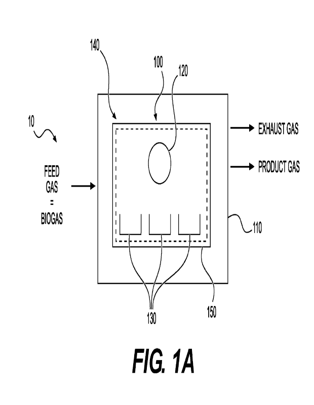
[0062] FIG.1A is a schematic illustration of a system for
processing biogas, according to
certain embodiments of the present disclosure;
[0063] FIG. 1B is a schematic illustration of a system for
processing biogas, according to
certain other embodiments of the present disclosure;
[0064] FIG. 2 is a schematic illustration of a portion of an
exemplary rotary valve for use in
the system, according to certain embodiments of the present disclosure;
[0065] FIG. 3A is a perspective view of a container for use with a system
for processing
biogas, according to certain embodiments of the present disclosure;
[0066] FIG. 3B is a side view of the schematic illustration of the
container of FIG. 3A,
according to certain embodiments of the present disclosure;
[0067] FIG. 3C is an end view of the schematic illustration of the
container of FIG. 3A,
according to certain embodiments of the present disclosure;
[0068] FIG. 3D is a top plan view of the schematic illustration of
the container of FIG. 3A,
according to certain embodiments of the present disclosure;
[0069] FIG. 4A is a side view of a schematic illustration of
another embodiment of the
container of FIG. 3A according to certain embodiments of the present
disclosure;
[0070] FIG. 4B is another side view of the container of FIG. 4A, according
to certain
embodiments of the present disclosure;
[0071] FIG. 4C is a top plan view of the container of FIG. 4A,
according to certain
embodiments of the present disclosure;
[0072] FIG. 5A is an end view of the container of FIG. 3A or 4A, showing PSA
unit modules
according to certain embodiments of the present disclosure;
[0073] FIG. 5B is a schematic illustration of the container of
FIG. 5A.
- 11 -
CA 03164069 2022- 7-7
WO 2021/138743
PCT/CA2021/050012
[0074]
FIG. 5C is a schematic illustration of another embodiment of the container
of FIG.
5A.
[0075] FIG. 6A
is a block flow diagram illustrating a method for processing biogas,
according to certain embodiments of the present disclosure;
[0076]
FIG. 6B is a block flow diagram illustrating a method for processing
biogas,
according to certain other embodiments of the present disclosure;
[0077]
FIG. 7 is a block flow diagram illustrating a method for processing
biogas, according
to certain embodiments of the present disclosure; and
[0078]
FIG. 8 is a block flow diagram illustrating a method for processing
biogas, according
to certain embodiments of the present disclosure.
DETAILED DESCRIPTION
[0079]
The present disclosure is not limited in its application to the details of
construction
and the arrangement of components set forth in the following description or
illustrated in the
drawings. The disclosure is capable of other embodiments and of being
practiced or of being
carried out in various ways. Also, the phraseology and terminology used herein
is for the
purpose of description and should not be regarded as limiting. The use of
"including",
"comprising", or "having", "containing", "involving" and variations thereof
herein, is meant to
encompass the items listed thereafter as well as, optionally, additional
items. In the following
description, the same numerical references refer to similar elements.
[0080]
Broadly, there are provided systems and methods for processing biogas, and
more
specifically systems and methods for purifying or refining biogas. In certain
embodiments, the
present systems and methods can provide processed biogas which can be used as
a pipeline gas
and meeting requirements of such a pipeline gas in terms of methane content
and impurities.
In other words, certain embodiments of systems and methods of the present
disclosure are for
refining a methane content of a biogas. The biogas (also referred to as "feed
gas" in the present
systems and methods) can be any gas that contains carbon dioxide and methane.
For example,
- 12 -
CA 03164069 2022- 7-7
WO 2021/138743
PCT/CA2021/050012
the feed gas call be derived from all anaerobic digester that is used to
digest animal waste, plant
waste, recovered organic municipal waste, dairy waste, solid and liquid
organic matter from a
waste water treatment plant.
100811 In
certain other embodiments, embodiments of the present systems and methods can
also be used to process other gases, such as to purify hydrogen, purify argon,
air separation,
helium recovery or carbon dioxide recovery.
100821 The feed gas may comprise other components in percentage and trace
amounts such
as CH4 %v/ppmv; CO2%v/ppmv; N2 %v/ppmv; 02;%v/ppmv, H20 %v/ppmv; H2S %Vippmv;
H2%V/ppmv NH3 %V/ppmv; Siloxanes %V/ppmv; BTEXN0Cs %V/ppmv; and Terpenes
%V/ppmv.
SYS'I'EMS
Broadly, embodiments of the system of the present technology comprise one or
more pressure
swing adsorption (PSA) units for processing the biogas at least partially
housed in a container.
The PSA unit operates based on adsorption, involving physical attraction of
certain molecules
in the feed gas onto the solid surface of a highly-porous material, followed
by regeneration at
lower pressure, which is based on lower adsorption capacity of that material
at lower pressure.
The pressure swings between high and low. Adsorption phenomena is governed by
adsorption
equilibrium and kinetic theory in certain embodiments. However, without being
limited to any
theory, in certain embodiments of the present technology, kinetics (e.g.
diffusion rate in the
adsorbent) is the limiting / deciding factor. Therefore, in certain
embodiments, the PSA unit /
method may be referred to as kinetic PSA (kPSA). Equally equilibrium
adsorption can be the
driving mechanism.
Pressure swing adsorption (PSA) unit
100831 Referring
initially to FIG. IA, there is illustrated one embodiment of a system 10 for
processing gas, such as biogas, in which a feed gas having a first composition
is processed to
output an exhaust gas having a second composition and a product gas having a
third
composition. In embodiments relating to biogas processing, the third
composition of the
product gas may have a higher relative methane concentration than the first
composition of the
- 13 -
CA 03164069 2022- 7-7
WO 2021/138743
PCT/CA2021/050012
feed gas. The third composition of the product gas may have a lower relative
water and/or
hydrogen sulfide concentration than the first composition of the feed gas. The
second
composition of the exhaust gas may have a higher relative carbon dioxide
concentration than
the first composition of the feed gas. The third composition of the product
gas may have a
higher methane concentration than the first composition of the feed gas. The
third composition
of the product gas may have a lower relative water and/or hydrogen sulfide
concentration than
the first composition of the feed gas.
100841
Broadly, the system 10 comprises at least one pressure swing adsorption
unit (PSA
unit) 100 housed in a container 110. This is also referred to as a
"containerized pressure swing
adsorption system". In certain embodiments, the system 10 may also include a
pre-treatment
assembly 112 and/or a post-treatment assembly 114 (FIG. 1B).
100851
In certain embodiments, the PSA unit 100 includes a rotary valve module
120 for
distributing flow of the feed gas in the PSA unit 100. In certain embodiments,
two PSA units
100 may be arranged in parallel with one another, with each of the two PSA
units treating a
portion of the feed gas flow. The portion may be half or any other fraction of
the feed gas flow.
The system 10 may be modular and configured such that the PSA unit(s) 100 can
be readily
installed and removed from the container 110.
100861
The PSA unit 100 comprises a plurality of beds (also referred to as
"adsorption beds"
and/or "vessels") 130 containing adsorbent material. In certain embodiments,
the PSA unit 100
comprises two or more beds 130 of adsorbent material. The adsorbent material
may be any
suitable material allowing methane recovery from the biogas. The adsorbent
material may be
any suitable material allowing removal of some or all of carbon dioxide,
oxygen and water in
the biogas, and allowing methane molecules to pass through the adsorbent
material. The PSA
unit 100 may also be capable of at least partially removing impurities such as
H20, H2S, volatile
organic compounds (VOCs) and siloxanes from the biogas stream. In certain
embodiments,
some methane may also be adsorbed.
100871
In certain embodiments, the adsorbent material is provided as a layer.
However, any
other configuration of the adsorbent material is possible. In certain
embodiments, there may be
provided a plurality of adsorbent materials of the same or different
configurations. A
- 14 -
CA 03164069 2022- 7-7
WO 2021/138743
PCT/CA2021/050012
combination of layers of adsorbent materials may be provided. In these
embodiments, the PSA
unit 100 may include layers of adsorbent materials.
100881 As noted above, the PSA unit 100 may comprise any number of beds 130 of
adsorbent material. In certain embodiments, there are provided any one of:
four, six, nine,
twelve, eighteen, or twenty-four beds 130 of adsorbent material. In certain
embodiments, the
PSA unit 100 comprises nine beds 130, which comprise identical, adsorbent
material. In certain
other embodiments, one or more of the beds 130 may be different. The beds may
be configured
for the feed gas to enter through the bottom of each bed 130 and for the
product gas to leave
from the top of the bed 130, while the separated contaminants are removed as
the exhaust gas
from the bottom of the bed 130. In certain embodiments, the beds 130 may be
configured to
transfer gas between one another. Any other suitable configuration is also
within the scope of
the present technology. I11 certain embodiments, the PSA unit 100 comprises
twelve beds 130
which are connected via the rotary valve module 120. All the steps occur via
the rotary valve
module 120 in certain embodiments. The rotary valve 120 rotation speed can
control the
product purity and recovery.
100891
Turning now to the rotary valve module 120, broadly, the rotary valve
module 120
can selectively connect different beds 130 of the PSA unit 100 to each other
in use. It may be
configured to permit simultaneous gas flow from one or more of the beds 130 in
use. For
example, in certain embodiments, the rotary valve module 120 is configured to
permit one or
more of the following: feed gas to the beds 130, permit flow between the beds
130, permit flow
out of the beds 130 to the exhaust, permit flow out of the beds 130 as the
product gas. In certain
embodiments, one or more of these steps may Occur concurrently in sequence and
controlled
by the rotary valve module 120. In this respect, the rotary valve module 120
may comprise a
plurality of ports.
100901
In certain embodiments, use of the rotary valve module 120 with the PSA
unit 100
replaces complex and bulky network of piping and multiple solenoid or actuated
valves used
in conventional PSA systems. Furthermore, by using the rotary valve module 120
with the PSA
unit 100, more beds 130 can be used compared to conventional PSA units. Each
bed 130 used
in embodiments of the present technology may be more compact than beds of
conventional
systems because of their increased number. In other words, the use of a rotary
valve module
120 can speed up the rate at which gas can be processed through the PSA system
which reduces
- 15 -
CA 03164069 2022- 7-7
WO 2021/138743
PCT/CA2021/050012
a size of vessels needed for a given gas flow. Faster cycle time translates to
significantly smaller
vessels compared to typical PSA units and can result in a compact unit with a
small footprint.
[0091]
In this respect, depending on the number of beds 130 provided, the rotary
valve
module 120 may comprise a four, six, nine or twelve bed ports, for example. In
certain
embodiments, the number of beds 130 provided can be increased by using two
beds 130 at a
time in parallel connected to the same port of the rotary valve module 120
allowing the rotary
valve 120 to connect to eighteen or twenty-four beds 130. The rotary valve
module 120 may
be arranged to operate two or more beds 130 of the plurality of beds
simultaneously.
[0092]
The rotary valve module 120 has a speed of rotation which can be
controlled
manually, automatically or semi-automatically. In this respect, in certain
embodiments, the
system 10 may further comprise a controller such as a processor of a computing
system,
operatively communicable with at least the PSA unit 100 or the rotary valve
module 120 of the
PSA unit 100 for controlling a valve rotation speed of the rotary valve 120.
The control of the
rotary valve module 120 rotation speed may be responsive to a methane or
biomethane content
of the exhaust gas. The rotary valve 120 rotation speed may control the
product purity and
methane recovery. In this respect, the system 10 may further comprise a gas
analyzer for
analyzing a parameter of the exhaust gas.
[0093]
In certain embodiments, the rotary valve module 120 comprises one or more
rotary
valves. The rotary valve module 120 may include two rotary valves, separated
by a shaft and
operated by a motor. One rotary valve may be connected to feed ends of the
adsorbent beds
130 and the other rotary valve to product ends of the adsorbent beds 130. FIG.
2 depicts a plan
view of a portion of an exemplary rotary valve that can be used within each
rotary valve module
120, which is further described in US 8,272,401, the contents of which are
herein incorporated
by reference. The rotary valve comprises a stator 2 and a rotor which can be
rotated about its
axis relative to the stator. Both the rotor and the stator include a plurality
of ports, such as the
ports 4 of the stator 132. As illustrated in FIG. 2, in certain embodiments,
the rotary valve
comprises nine circular ports 134 spaced equidistantly from each other but
could comprise any
number of ports of any other shape. As the rotor rotates about its axis, the
ports of the rotor and
the stator are brought into and out of alignment, functioning as multiple
valves.
- 16 -
CA 03164069 2022- 7-7
WO 2021/138743
PCT/CA2021/050012
[0094]
The system 10 may include more than one PSA unit 100, each one of the
plurality
of PSA units 100 each having a single rotary valve module 120 for distributing
flow of the
biogas in the given PSA unit 100. The plurality of PSA units 100 can be
arranged in parallel,
with a flow capacity of at least one of the plurality of PSA units 100 being
about half of a
maximum flow capacity of the system 10. In other embodiments, the flow
capacity of at least
one of the PSA units 100 is any other fraction of the maximum flow capacity of
the system 10.
[0095]
In certain embodiments, the PSA unit 100 is configured as a PSA unit
module 140
which can be removably housed within the container 110. In this respect, the
PSA unit module
140 comprises a PSA unit housing 150 sized and shaped to house the beds 130
and the rotary
valve module 120. The PSA unit module 140 may further house one or more of: a
compressor
for compressing the feed gas, and a vacuum pump for applying negative
pressure. In certain
embodiments, the PSA unit module 140 includes a PSA unit 100 without the
rotary valve
module 120.
Container
[0096] Certain non-limiting embodiments of the container 110 are illustrated
in FIGS. 3-5.
Broadly, the container 110 comprises walls 210 (such as two side walls and two
end walls), a
roof 220 and a floor 230 defining an internal storage space 240. The container
110 is configured
to support equipment, such as by housing the equipment within the internal
storage space 240,
or by supporting the equipment on the roof 220 and/or the walls 210.
[0097] In certain embodiments, the container 110 is configured to support the
equipment on
the roof 220 of the container 110. As seen in FIGS. 3A-D, tanks, amongst other
equipment can
be seen supported on the roof 220. In this respect, the container 110 is
configured to provide
access to the roof 220 of the container 110 to a user of the system 10, such
as for maintenance
or the like. In certain embodiments, the container 110 also includes a railing
250 extending
around at least a portion of a perimeter of the roof 230.
[0098] The container 110 includes, in certain embodiments, a supporting
structure 260
removably positionable on the roof 220 of the container 110. The supporting
structure 260 is
configured to be assembled to the roof 220, and the equipment to be placed on
the supporting
structure 260. The equipment can be placed on the supporting structure 260
before or after its
assembly to the roof 220. In this way, the container 110 has a modular
structure enabling the
- 17 -
CA 03164069 2022- 7-7
WO 2021/138743
PCT/CA2021/050012
transportation of the container 110 in two parts: the removeable supporting
structure with the
items of equipment to be stored on the roof 220, and the container 110 and its
contents. The
modularity can best be seen in FIG. 3A.
[0099] In certain embodiments, the container 110 is configured to support the
equipment on
one or more of the walls 210. Brackets 270 or other support units may be
provided for wall
support. For example, brackets 270 are provided on the side wall of the
container 110 in FIG.
3C. In FIG. 3C, for example, a heat exchanger can be seen supported on the
bracket 270 on the
side wall, with fluid conduits extending through the side wall.
[00100] The container 110 includes, in certain embodiments, one or more doors
280 for
accessing the internal storage space 240. At least one of the doors 280 may be
incorporated in
the side wall of the container 110 or the end wall (FIGS. 3B and 3C). At least
one of the doors
may comprise a single door, a double door, or a cargo door.
[00101] The container 110 is made, in certain embodiments of steel, such as
reinforced steel.
However, it will be appreciated that the container 110 may be made of any
other suitable
material. The container 110 may comprise an unmodified or modified shipping
container, such
as a 40 foot high sea container. The container may be configured to support a
load of about
60,000 lb.
[00102] The walls 210, floor 230 and roof 220 of the container 110 may be
configured to fluidly
seal the internal storage space 240.
[00103] Turning now to the container 110, the container 110 may be any
suitable size or shape
for housing the one or more PSA unit(s) 100 or the PSA modules 140. In certain
embodiments,
the container 110 is 2.43 m wide, 2.59 m high, and either 6.06 m long or 12.2m
long. In certain
other embodiments, the height of the container 110 may be 2.89 m high. In
certain other
embodiments, exterior dimensions of the container 110 may be about 12.2 m long
>< about 2.4
m wide x about 3.0 m high, or about 6.1 m by about 2.4 m by about 2.6 m.
External dimensions
and nominal capacities of certain embodiments of the container 110 are set out
in Table 1.
Table 1: Container dimensions and nominal system capacities, according to
certain
embodiments of the present technology
- 18 -
CA 03164069 2022- 7-7
WO 2021/138743
PCT/CA2021/050012
Container dimensions! LxW Nominal capacity
Example 1 15 m x 2.3 m 225 Nm3/h*
(49x8 foot) (140 SCFM**)
Example 2 15 m x 2.3 in 450 Nm3/h*
(49 x 8 foot) (280 SCFM**)
* Normal m3 per hour
** Standard cubic feet per minute
Other sizes and nominal capacities of embodiments of the container 100 and
system 10 are
within the scope of the present technology.
1001041 At least some of the equipment housed or supported by the container
110 may relate
to embodiments of the biogas method or system 10 as described herein. In this
respect, in
certain embodiments, the container 110 is configured to house the one or more
PSA units 100
which may or may not include the rotary valve module 120. In certain other
embodiments, the
container 110 is additionally configured to house all or some components of
the pre-treatment
assembly 112, such as one or more of: a water removal unit, a light recycle
pump, a vacuum
pump, a compressor and an analyzer. In certain other embodiments, the
container 110 is
1 5 alternatively or additionally configured to house components of the
post-treatment assembly
114. In certain embodiments, the container 110 is configured to house one or
more of: a power
and control unit including a processor, a supply of air, air compressor, and a
source of oxygen
(e.g. FIGS. 5B and 5C).
1001051 In certain embodiments, the container 110 is configured to house or
support equipment
relating to another industrial process, such another biogas process. For
example, the container
110 may be configured for treating digester gas from digesters in waste water
plants.
1001061 In certain embodiments, the container 110 may be divided into two or
more
compartments by one or more internal partitions (e.g. as shown in FIGS. 5A-
5C). The
partition(s) may fluidly separate the two compartments from one another. One
compartment
may be configured to house electrical components. One or both of the
compartments may be
environmentally controlled (for temperature, humidity, smoke, etc.). Emergency
shut down
- 19 -
CA 03164069 2022- 7-7
WO 2021/138743
PCT/CA2021/050012
sensors for monitoring the environment may be included within one or more of
the
compartments.
[00107] Developers have discovered that, not only does the ability to support
equipment on the
roof 220 of the container 110 have space saving and transportation advantages,
but surprisingly,
in certain embodiments, it can provide improvements to the industrial process
due to elevation
of certain equipment.
[00108] For example, in certain embodiments, the container 110 is configured
to support one
or more surge tanks 290 on the roof Surge tanks 290 may be included in a
system 10 for biogas
treatment which includes a rotary valve module 120. Such a system 10 may
differ from the
biogas systems described herein. In certain embodiments, the one or more surge
tanks 290 may
be included on a recycle line of the PSA unit 100, and/or on an exhaust line
of the PSA unit
100, and optionally include a blower (FIG. 613). Further description of the
surge tanks 290 arc
included in a corresponding patent application US 63/108,769 entitled "SYSTEM
FOR
RECOVERING METHANE FROM A BIOGAS filed on November 2, 2020, the contents of
which are hereby incorporated by reference in their entirety.
[00109] Surprisingly, in certain embodiments, positioning of the surge tanks
290 in a closer
proximity to the PSA unit 100 may an improve gas recovery rates in biogas
processes, as well
as reducing noise and wear. In certain embodiments, positioning of the surge
tanks 290 on the
roof 220 of the container 110 permits use of a larger surge tank 290 which has
greater gas
recovery advantages.
[00110] The embodiment of the container 100 depicted in FIGS. 4A and 4B
differs from the
container 100 of FIGS. 3A-3D in that there is no equipment on the roof 220.
[00111] Turning to FIGS. 5A-5C, there is depicted another embodiment of the
container 100
of FIGS. 3A-3D in that the one or more PSA units 100 are provided as PSA unit
modules 140
having the PSA unit housings 150. The PSA unit modules 140 are configured to
be removably
placeable in the container 110. The PSA unit modules 140 may be sized and
shaped to be
positioned in a side-by-side configuration in the container 110 as shown in
FIGS. 5A and 5B,
or in any other suitable configuration such as vertically stacked. In this
respect, the system 10
may be considered as a modular system 10 including one or more of the PSA unit
modules
- 20 -
CA 03164069 2022- 7-7
WO 2021/138743
PCT/CA2021/050012
140, at least one of the PSA unit modules including the PSA unit 100 including
the rotary valve
120 housed in the housing 150. The PSA modules 140 may be the same or
different to one
another. For exa140140
[00112] mple, one PSA module may have a higher capacity than the other.
[00113] In certain embodiments, one advantage of such modularity relates to
ease of expanding
or reducing a capacity of the system 10. Indeed, system capacity can be
expanded by simply
providing one or more additional PSA unit modules 140 in its respective
housing 150.
Similarly, system capacity can be reduced by removing the PSA unit module 140
in its housing
150. Such a standardization of a system, rather than bespoke gas processing
plants, translate to
cost savings. In fact, in certain embodiments, a cost of manufacture of a
single biogas
processing plant of the prior art is equivalent to the manufacture of three
systems 10
(containers) of the present technology. In other words, embodiments of the
present system 10
can provide cost efficiencies compared to conventional biogas processing
plants of a magnitude
of about threefold.
[00114] In certain embodiments, another advantage of such a modular system 10
relates to ease
of access to parts of the system 10 for maintenance and repair access. The
container 110 may
be a small space which makes it difficult to get access to all parts of the
equipment. This is
particularly relevant when two PSA units 100 are used. By means of certain
embodiments of
the present technology, access to parts of the system 10, such as the PSA
unit(s) 100, can be
achieved by removal of that PSA unit module 140 from the container 110,
without necessarily
having to remove other components. The PSA unit module 140 can be simply slid
out.
[00115] In certain embodiments, the system 10 is provided with other
components that are
arranged to be housed in the container 110, and that may or may not be part of
the PSA unit
100, the pre-treatment assembly 112 or the post-treatment assembly 114. These
components
include, without limitation, one or more of: a feed gas blower, an air
compressor, a gas
compressor, an oxygen generator, a gas analyzer, a heat exchanger, an
economizer, a heat
transfer unit, electrical switch gear, and a vacuum pump housed on a separate
support for ease
of removal and/or maintenance.
[00116] In certain embodiments, the system 10 includes one or more external
assemblies,
operatively connected to the PSA unit 100, but positioned largely outside of
the container 110.
-21 -
CA 03164069 2022- 7-7
WO 2021/138743
PCT/CA2021/050012
The external assemblies may include one or both of the pre-treatment assembly
112 and the
post-treatment assembly 114 (FIG. 1B) positioned upstream and downstream of
the PSA unit
100, respectively. The pre-treatment and the post-treatment assemblies 112,
114 may include
at least some components that are positioned within the container 110.
Pre-treatment assembly
[00117] The pre-treatment assembly 112, when present in the system 10, is
upstream of the
PSA unit 100 and pre-treats the biogas before it is supplied to the PSA unit
100. The pre-
treatment assembly 112 is arranged to pre-treat the biogas to remove certain
contaminants, such
as one or more of: hydrogen sulfide, volatile organic compounds, siloxanes and
water.
[00118] In certain embodiments, the pre-treatment assembly 112 comprises: a
water removal
unit 300 for removing water from the biogas (also referred to as de-watering)
(FIGS. 6 -8). In
certain embodiments, the water removal unit 300 comprises a water chiller
package 305, such
as a heat exchanger to cool the biogas, such as to a few degrees to above
freezing which can
remove water and heavy condensable components at low pressure.
[00119] In certain embodiments, the pre-treatment assembly 112 also includes a
hydrogen
sulfide removal unit 310 for removing hydrogen sulfide from the biogas (FIGS.
6-8). In certain
embodiments, the hydrogen sulfide removal unit 310 comprises a tower
containing an
adsorbent for removing one or both of hydrogen sulfide and volatile organic
compounds.
[00120] In certain other embodiments of the pre-treatment assembly 112, the
hydrogen
sulfide removal unit 310 may be included after the biogas compression stage,
permitting it to
be operated at higher pressure.
[00121] A blower 320 may be provided for pushing the gas through the pre-
treatment
assembly 112 from the water removal unit 300 to the hydrogen sulfide unit 310.
Post-treatment assembly
[00122] The system 10 may comprise a post-treatment assembly 114 downstream of
the PSA
unit 100 for treating the product gas from the PSA unit 100. The post-
treatment assembly 114
may include one or more of a gas compression unit 330 to compress the
processed gas, a de-
- 22 -
CA 03164069 2022- 7-7
WO 2021/138743
PCT/CA2021/050012
oxygenation unit 340 to de-oxygenate the processed biogas, an exhaust
treatment 350, and a
carbon dioxide recovery unit 360 to recover some carbon dioxide.
METHODS
[00123] Certain methods of biogas processing according to certain embodiments
of the
present technology will now be described with reference to FIGS. 6-8. Certain
embodiments
of the method may comprise a cyclic repetition of one or more of the following
steps:
adsorption / production; de-pressurization; recycle; regeneration /
desorption; equalization, and
pressurization. One or more of these steps may be performed by one or more
components of
the present system 10, such as the PSA unit 100, the pre-treatment assembly
112 and the post-
treatment assembly 114.
Adsorption/Production Step
[00124] In this step, pressurized biogas is fed into the bottom of the bed 130
or beds 130
(adsorption vessel(s)) filled with the adsorbent material, and biomethane is
allowed to
continuously leave from the top of the bed 130. The pressurized biogas may be
pre-treated.
CO2 molecules not only have a higher affinity towards the adsorbent surface,
but also have
smaller kinetic size than the large and bulky CH4 molecules. Consequently CO2
can rapidly be
retained by the adsorbent surfaces and access its inner surface structures.
Improved adsorption
equilibrium and faster kinetics make the adsorbent highly selective towards
CO?, while a large
proportion of CH4 molecules pass through the bed un-adsorbed, resulting in a
purified methane
product.
[00125] In certain embodiments, in which the PSA unit 110 comprises a
plurality of beds
130, the pressurized biogas may be fed to each bed of the plurality of beds
130 sequentially.
The sequence may comprise one bed at a time or groups of beds at the same
time.
De-pressurization Steps
[00126] Before the bed 130 is fully saturated by CO2, the method comprises
switching the
feed to another bed 130 in order to prevent the non-methane components from
"breaking
through" and contaminating the product.
- 23 -
CA 03164069 2022- 7-7
WO 2021/138743
PCT/CA2021/050012
[00127] Pressure is reduced to low pressure to regenerate the CO2 saturated
bed 130. This
pressure reduction process is done in a series of steps. At the end of the
adsorption step, the
rotary valve module 120 connects two designated beds 130, a first bed and a
second bed,
together. This step is called equalization and allows the first bed to
transfer some un-adsorbed
gas to the other bed and retains some methane-rich gas inside the system,
hence increasing the
overall recovery. This step also helps the next bed 130 in the pressurization
process by injecting
high-pressure gas into the bed 130, which results in energy saving by reducing
compressor
duty. The high pressure gas can also be derived from other depressurizing
vessels.
[00128] After the first equalization, additional equalization steps may be
performed by
causing the rotary valve module 120 to connect the bed 130 to other beds in
sequence with
lower pressures in different stages of pressurization. These equalization
steps improve the
process overall methane recovery.
Recycle Step
[00129] At this point the given bed 130 has gone through equalization steps,
and most of the
methane-rich gas has been removed from the given bed 130 and transferred into
other beds.
However, the bed 130 may still contain a considerable amount of valuable
methane. In order
to increase the overall recovery even further, the bed 130 is depressurized to
a predetermined
pressure by causing it to flow to the inlet of the system 10 (recycling). The
predetermined
pressure may be any pressure lower than a pressure of the bed 130, such as but
not limited to
atmospheric pressure. The flow rate of the recycled stream is less than 25% of
the raw biogas
flow rate, so it does not increase the load of the compressor significantly.
The recycled stream
can increase the overall methane recovery by up to about 12% in certain
embodiments.
Regeneration/Desorption Step
[00130] In this step, adsorbed impurities such as CO2, N2, and 02 are released
into the gas
phase under reduced pressure or vacuum conditions applied by a vacuum pump,
for example.
They form a contaminant-rich exhaust stream, which also contains a small
quantity of methane.
This stream is removed from the bed 130 through an exhaust port. The system 10
may be
configured such that when the maximum vacuum is attained, nearly all the
contaminants have
been removed from the adsorbent media of the bed 130. The method may comprise
proceeding
to a subsequent step only when the maximum vacuum is attained.
- 24 -
CA 03164069 2022- 7-7
WO 2021/138743
PCT/CA2021/050012
Pressurization Steps
[00131] A regenerated adsorbent bed 130 needs to be pressurized before going
through
another adsorption cycle. At the end of the regeneration step, the
pressurization process starts
and in a series of steps, the rotary valve module 120 connects the bed 130 to
other beds 130
going through third, second and first equalizations, respectively. In other
embodiments there is
included one or more of first, second, third and fourth equalization steps
depending on the
number of beds 130 in the PSA unit 100. In other embodiments there is included
first, second,
third, fourth and fifth equalization steps depending on the number of beds 130
in the PSA unit
100. This may result in a stepwise increase in pressure within the bed 130.
Equalization steps
take advantage of high-pressure gas available from other beds 130 and reduce
the energy
needed for the compression step of the process. Equalization steps can be
coordinated and
controlled by the rotary valve module 120.
[00132] After the completion of equalization steps, the bed 130 is connected
from the top to
the product line and is pressurized using a small portion of the methane rich
product gas. Then
the rotary valve module 120 connects the bed 130 from the bottom to feed
stream to pressurize
the bed 130 to the final pressure and complete the pressurization step. After
this step the bed
130 is fully regenerated and re-pressurized, and is ready to go through
another cycle.
[00133] In certain embodiments, the PSA unit 100 operates as a single stage
PSA unit.
[00134] A method of processing a biogas according to certain embodiments of
the present
technology broadly comprises supplying the feed gas to one or more embodiments
of the
system 10 as described herein and/or defined in any of the claims. More
specifically, the
method comprises supplying feed gas to the system 10 comprising the container
110, and at
least one PSA unit 100 housed in the container 110, the PSA unit 110 having a
rotary valve
module 120 for distributing flow of the biogas in the PSA unit 110, and
allowing the feed gas
to contact adsorbent material in the PSA unit 110. The adsorbent material is
arranged to permit
the movement of methane therethrough. In certain embodiments, the method
further comprises
one or both of a pre-treatment step executed by the pre-treatment assembly
112, for example,
and a post-treatment step executed by the post-treatment assembly 114, for
example.
Method embodiments of Figures 3-6
- 25 -
CA 03164069 2022- 7-7
WO 2021/138743
PCT/CA2021/050012
[00135] Specific reference is now made to the embodiments illustrated in FIG.
1B, 6A and
FIG. 8 in which the system 10 and/or method includes one or both of a pre-
treatment and a
post-treatment assembly / step. It has been found that in certain
circumstances in order to
convert raw biogas or other fuel gas into biomethane or a renewable natural
gas, a series of
bulk separation, contamination removal and gas conditioning processes are
required that can
be divided into three major steps: a pre-treatment step to remove contaminants
such as water,
H2S, VOC and siloxanes; a post-treatment step to remove CO2 and some 02. In
FIG. 8, at least
some of the components external to the container 110 are indicated as
"optional-.
Pre-Treatment steps
Low-Pressure De-watering
[00136] The biogas is cooled to a few degrees above freezing to condense most
of the water
and heavy condensable components at low pressure, by the water removal unit
300 for
example. The blower 320 can be used to increase the pressure slightly to push
the gas through
the pre-treatment assembly 112. The biogas can then pass through the hydrogen
sulfide
removal unit 310. The hydrogen sulfide removal unit 310 may comprise an
adsorption tower
filled with an adsorbent. The adsorbent may comprise activated carbon,
impregnated activated
carbon, or any other adsorbent for hydrogen sulfide adsorption and which can
remove H2S and
VOCs before the main upgrading (post-treatment) step. Alternatively, the
hydrogen sulfide
removal unit 310 may comprise a hydrogen sulfide treatment unit that can
operate aerobically,
anaerobically, or a combination of aerobically and anaerobically.
Biogas compression
[00137] The PSA unit 100 operates at medium pressure range, so biogas needs to
be
pressurized before being processed in the PSA unit 100. In this respect, the
system 10 may
include one or more compressors such as the compressor 330. In certain
embodiments, oil-
flooded screw compressors may be used as the compressor 330 for biogas
compression.
[00138] Optionally, biogas may, in certain embodiments, first be mixed with a
small stream
of recycled gas from the PSA unit 100 and then compressed in a single-stage,
oil-flooded screw
compressor to a pressure of about 6.9 to about 9 barg (about 100 - 130 psig),
about 4.5 to about
6.9 barg, about 7.6 to about 8.3 barg (about 110-120 psig), or about 120-250
psig. In certain
embodiments, the pressure is between about 3.5 barg to about 18 barg , between
about 4 barg
to about 12 barg, between about 5 barg to about 10 barg, or between about 5
barg to about 10
- 26 -
CA 03164069 2022- 7-7
WO 2021/138743
PCT/CA2021/050012
burg. However, it should be noted that the recycled gas stream mixing is an
optional
embodiment, and in certain embodiments, there is no recycled gas component.
High-Pressure de-watering
[00139] This step follows gas compression in certain embodiments. In general,
two methods
can be used to remove the condensable components: decreasing the temperature
below the dew
point and increasing the pressure above the saturation pressure. In order to
take advantage of
both concepts, a second deep-cooling stage at high pressure may be included in
addition to the
low-pressure cooling at the start of the process, in certain embodiments. This
maximizes the
removal of water and other contaminants such as VOCs, siloxancs and oil vapor
from the
Compressor.
[00140] Compressed biogas is first cooled with an economizer and a cooler, and
then chilled
using a gas / liquid heat exchanger to a few degrees above freezing, which
condenses most of
the remaining humidity from the biogas. Condensed water is then removed. It
contains trace
amounts of H2S, VOCs, siloxanes, and compressor oil. Finally, a re-heater de-
saturates the
compressed biogas to eliminate the possibility of condensate formation in the
subsequent
equipment.
PSA unit treatment steps
[00141] Next, the gas is wholly or partly delivered to the PSA unit 100. In
the cyclic process
described above for biogas, CO2, and other impurities are wholly or partially
removed from the
biogas by the PSA unit 100. In other embodiments focused on purification or
separation of
other gases, other impurities may be wholly or partially removed (such as N2,
02). In yet other
embodiments, the gas is first compressed, hydrogen sulfide removed such as by
an activated
carbon tower, before being passed to the PSA unit 100. In certain embodiments,
the gas may
be reheated, such as using heat from the compression, before being delivered
to the PSA unit
100.
[00142] After the pre-treatment is complete, optionally, the biogas can be
further processed
by removing one or more of: CO2, N2 and 02. In anaerobic digester or anaerobic
digestion
applications, N2 and 02 contamination is minimal (usually <1%), which reduces
the complexity
of the separation and limits it to a single-stage PSA unit CO2 separation with
partial or no N2
- 27 -
CA 03164069 2022- 7-7
WO 2021/138743
PCT/CA2021/050012
and 02 separation. The single-stage PSA unit is to be differentiated from
systems having
multiple PSA units operating in series.
Product compression
[00143] Gas compression may occur either to the feed gas, or as a post-
treatment step to the
product gas. In the latter case, a product compressor, such as the gas
compressor unit 330, may
be used to compress the product gas. The product gas can be delivered at any
pressure
between 5 and 5000 psig.
Examples
Referring to Tables 2-6, certain measured parameters of embodiments of the
present system 10
and methods are depicted. Table 2 depicts example parameters of the feed gas
according to
certain embodiments of the present systems 10 and methods. Table 3 depicts raw
biogas,
product gas and exhaust gas values for two example systems and methods
according to
embodiments of the present technology. Table 4 depicts performance obtained by
certain
embodiments of the present system and method. Table 5 provides an overview of
parameters
in certain embodiments of the present technology. Table 6 depicts feed gas and
product gas
specifications in certain embodiments.
Table 2 feed gas minimum and maximum values for individual parameters (wet
basis)
Parameter Minimum Maximum
(wet basis) (wet basis)
Flow (NCMH) 225 450
Flow (scfm) 139 280
Pressure (barg) 0.004 0.5
Temperature ( C) 4 35
Temperature ( F) 45 87
CH4 (vol /0) 45 70
CO2 (vol /0) 30 65
N2 (vor/o) 0 0.8
02 (V01%) 0 0.1
N2+02( Vol%) 0 0.9
H20 (vol /0) dry 5.25
H2S (ppmv) 0 250
- 28 -
CA 03164069 2022- 7-7
WO 2021/138743 PCT/CA2021/050012
NNIVOC (ppmv) 0 250
The lower pressures are achieved without a compressor, and the higher
pressures are achieved
with the compressor 330.
Table 3. Raw biogas, product gas and exhaust gas values for two example
systems
according to embodiments of the present technology
Example 1 Example 2
Parameter Unit Raw Raw
Product Exhaust . Product
Exhaust
Biogas Biogas
Flowrate NCMH 225 117 94 450 234 189
scfm 140 73 59 280 146
118
Peak capacity NCMH 230 120 97 460 239 193
scfm 143 75 60 287 149
120
Turndown NCMH 90 54 31 180 108 61
scfm 56 34 19 112 67
38
Temperature C 39 20 20 39 20
20
F 102 68 68 102 68
68
Pressure psig 0.3 100 1 0.3 100
1
barg 0.02 6.9 0.07 0.02 6.9
0.07
CH4 vol% 51.2 97.0 1.8 51.2 97.0
1.8
CO2 vol% 42.3 2.2 98.0 42.3 2.2
98.0
N2 vol% 0.4 0.7 0.04 0.4 0.7
0.04
02 vol% 0.1 0.1 0.1 0.1 0.1
0.1
D.P. D.P.
H20 vol% 6.0 -40 F -40 F 0.05
6.0 0.05
H2S PPMV 200.0 2.0 8.0 200.0
2.0 8.0
Total vol% 100.0 100.0 100.0 100.0 100.0 100.0
D.P. - dew point
Table 4. Performance of embodiments of the present system and method
Performance Indicator Biogas plants implementing
embodiments of the
present method and system
Cost Two cost levels depending on feed
gas capacity
- 29 -
CA 03164069 2022- 7-7
WO 2021/138743
PCT/CA2021/050012
Efficiency >95% methane recovery
Electricity consumption (kW) 99
Electrical Usage (kWh/NCM feed 0.22
processed
Feed gas variability Reasonable tolerant to variability
in feed gas
composition and flows
Table 5. Overview of system / method parameters in certain embodiments of the
present
technology
System / Method Parameters Commercial operation
Plant capacity 225 NCMH and 450 NCMH
Process efficiency as methane recovery > 98%
Electricity consumption (kW) <100
Electrical usage (kWh/NCM feed processed) <0.23
Product gas Quality HHV MJ/Nm3 >36
Product dew point C -30
Process availability in 3 month period 98%
Plant automation Automated operation,
including
remote start-up
Time to deploy and commission on site: 2 weeks maximum
Table 6. Feed gas and product gas specifications in certain embodiments
Raw biogas Product
Flow (SCFM) (wet) 50 ¨ 290 25 - 179
Pressure (psig) 0.0 ¨ 0.9 0 - 4000
Temperature ( F) 34 ¨ 104 < 110
CH4 (vol%) (dry) 35 ¨ 70 90 - 98
CO2 (vol%) 29 ¨65 2 ¨ 3.4
N2 (V01%) <0.8 <= 1.6
02 (vol%) <0.3 <= 0.4
H20 Saturated Water dew point < -30 F
H2S (ppmv) 20 <2
HHV (Btu/scf) 860 - 988.7
Wobbc index (Btu/set) 1275 - 1305
- 30 -
CA 03164069 2022- 7-7
WO 2021/138743
PCT/CA2021/050012
[00144] In certain embodiments, at least one or more components of the system
10 are housed
or supported by the container 110, including one or more of the pre-treatment
assembly 140,
compression equipment, and one or two (or more) PSA units 100. There may be
provided a
processor to control the PSA unit(s) 100. In certain embodiments, the
container 110 houses the
pre-treatment assembly 140 with the exception of hydrogen sulfide adsorption
tower(s), if
present.
[00145] Variations and modifications will occur to those of skill in the art
after reviewing this
disclosure. The disclosed features may be implemented, in any combination and
subcombinations (including multiple dependent combinations and
subcombinations), with one
or more other features described herein. The various features described or
illustrated above,
including any components thereof, may be combined or integrated in other
systems. Moreover,
certain features may be omitted or not implemented. Examples of changes,
substitutions, and
alterations are ascertainable by one skilled in the art and could be made
without departing from
the scope of the information disclosed herein.
[00146] It should be appreciated that the invention is not limited to the
particular embodiments
described and illustrated herein but includes all modifications and variations
falling within the
scope of the invention as defined in the appended claims.
- 31 -
CA 03164069 2022- 7-7