Note: Descriptions are shown in the official language in which they were submitted.
WO 2021/124332
PCT/112020/051301
GASEOUS MATTER CAPTURE SYSTEM AND METHOD
FIELD OF THE INVENTION
The present invention relates to the field of gaseous matter capture, and,
more particularly,
but not exclusively, to capturing carbon dioxide directly from the atmosphere
for the purposes of
climate change mitigation and further use of captured gases.
BACKGROUND OF THE INVENTION
Climate change has long been a global concern having a potential enormous
impact on the
global environment and human wellbeing. Human activities such as the
combustion of fossilized
fuels and deforestation, along with derivative phenomena such as accelerated
permafrost thawing,
increase the amount of greenhouse gases in the earth's atmosphere and cause
the global climate to
change. As a result, many concepts were tested and implemented in order to
mitigate the effects
of climate change.
Nowadays, the Carbon Dioxide concentration in the earth's atmosphere is 411
parts per
million (ppm). This amount increases by over 2 ppm per year, due to the
continued emissions in
the multiple and distributed sectors of the world's economy. According to the
Paris Agreement led
by the UNFCCC and signed by most countries in 2015, mankind has to limit the
average
temperature increase to 'welt below' 2 C compared to pre-industrial levels, in
order to avoid
catastrophic consequences. In order to try and predict how to avoid said
potentially catastrophic
2 C increase limit, models vary between allowing for a remaining carbon quota,
but generally aim
at remaining below 430 ppm, whereas 450 ppm indicates an approximate
transition to a high
probability of irreversible effects as one ppm roughly translates to several
Billions of metric tons
1
CA 03158823 2022-5-18
WO 2021/124332
PCT/1L2020/051301
of CO2, this implies the need to remove green-house gases from the atmosphere
in the order of
tens of Billions tons per year.
A variety of carbon dioxide capture methods have been described in the art.
Among them
are scrubbers configured to be implemented in streams of high carbon dioxide
concentrations like
those found in exhausts of power plants, industrial facilities or vehicles..
Although such methods
of capturing carbon from flue gas may provide some mitigation to the
continuous increase in
carbon emissions, they are limited in their applicability, cannot address
carbon emissions from
distributed sources and also cannot address the high carbon dioxide
concentration already
circulating as part of the earth's atmosphere.
The capturing of carbon dioxide directly from the earth's atmosphere using
chemical
processes of different types has been disclosed by several publications, for
example, patent
applications publications US20170106330A1 and US20170028347A1 disclose the
capturing of
carbon dioxide conducted by stationary, terrestrial systems using sodium
hydroxides that later
allows compression of a high purity carbon dioxide stream into liquids or
supercritical liquids.
Other means of chemical and physical capturing and processing of carbon
dioxide have been
disclosed, for example, in patent applications publications W02016185387A1,
AU2008239727B2
and US20140061540A 1_ Patent publications US4963165A and US8702847B2 also
disclose the
capturing, separating, condensing and recycling of carbon dioxide.
Patent applications publication US20170106330A1 discloses a system for
separating and
storing molecules, atoms and/or ions from air, comprising at least one
collecting tank configured
to receive molecules, atoms and/or ions that are separated from ambient air.
The system further
2
CA 03158823 2022-5-18
WO 2021/124332
PCT/1L2020/051301
comprising at least one storing tank for storing the separated molecules,
atoms and/or ions, and at
least one outlet, wherein the air collecting means can be a gas tower or a gas
balloon.
Patent applications publications US20110146488A discloses capturing and
sequestering
significant amounts of carbon dioxide molecules from an incoming air stream by
directing flow
into an airborne cylindrical carbon composite canister, or "Atmospheric Carbon
Dioxide
Mitigation" (ATCOM) canister which has the capacity to capture, sequester, and
then release the
species with negative ionization within a desired high frequency
electromagnetic wave field. The
initial airflow into the ATCOM canister is slowed to a specific flow velocity
as the air stream
travels through a volute chamber with resistance added impellers, and then
into a free flow
chamber where the incoming flow velocity compresses the air volume, allowing
for an osmotic
equality distribution of the concentration of CO2 molecules.
From the state of the art indicated above, one can notice that different
trials and
development are being conducted, although generally these efforts do not
manage to meet the
market requirements in terms of price, mitigation (with regard to carbon
emissions per ton of
carbon dioxide captured) and applicability.
Neither of the publications indicated above do not teach, alone or in
combination, a gaseous
matter capture system, comprising an aerial unit and a non-aerial unit and
configured to transfer
the stored separated gaseous matter from the aerial unit to the non-aerial
unit for further processing
or storage.
There is a need to provide a system and method for capturing gaseous matter
directly from
the atmosphere in an economical, scalable and applicable manner.
3
CA 03158823 2022-5-18
WO 2021/124332
PCT/1L2020/051301
There is a further need to provide a system and method configured to release
storage means
full of compressed gaseous matter for further processing by a non-aerial unit,
thus increasing the
gaseous matter collecting efficiency by allowing to capture more gaseous
matter such as carbon
dioxide mass in a single airborne mission hence reducing regular maintenance
and ground time
intervals.
SUMMARY OF THE INVENTION
The present invention provides a system and method for capturing gaseous
matter directly
from the atmosphere which is economical and highly scalable with regard to any
other available
system and method.
Said system and method may further include using the climatic conditions found
at high
altitude that enable gases' phase transitions at low temperatures and
relatively low pressures in
order to liquefy or solidify gaseous matter such as carbon dioxide, and thus
separate it from the
other gases forming the atmospheric mixture.
Said system and method may further include utilizing high altitude
platform/vehicle such
as a high-altitude balloon configured to capture large amounts of high
altitude gaseous matter such
as CO2, wherein said high altitude CO2 concentration tends not to be diluted
due to the typical
strong winds and resulting advection.
Said system and method may further include transferring the stored separated
gaseous
matter from the aerial unit to the non-aerial unit for further processing or
storage.
4
CA 03158823 2022-5-18
WO 2021/124332
PCT/1L2020/051301
Said system and method may further include increasing the gaseous matter
collecting
efficiency by allowing to capture more gaseous matter such as carbon dioxide
mass in a single
airborne mission hence reducing regular maintenance and ground time intervals.
The following embodiments and aspects thereof are described and illustrated in
conjunction with systems, devices and methods which are meant to be exemplary
and illustrative
and not limiting in scope. In various embodiments, one or more of the above-
described problems
have been reduced or eliminated, while other embodiments are directed to other
advantages or
improvements.
According to one aspect, there is provided a gaseous matter capture system,
comprising at
least one aerial unit configured to be airborne, at least one non-aerial unit,
at least one gas
separation means configured to be carried by the aerial unit, storage means
configured to be carried
by the aerial unit, a controller configured to control the system's operation
and an energy source
configured to enable the system's operation, wherein the at least one gas
separation means is
configured to separate at least one designated gaseous matter from the air,
wherein the at least one
separated gaseous matter is configured to be stored within the storage means
and wherein the aerial
unit is configured to transfer the stored separated gaseous matter to the non-
aerial unit.
According to some embodiments, the at least one gas separation means is
operable while
the aerial unit is airborne at an altitude range of 5-15 km.
According to some embodiments, the gas separation means comprises at least one
pressure
increasing apparatus.
5
CA 03158823 2022-5-18
WO 2021/124332
PCT/1L2020/051301
According to some embodiments, the gas separation means comprises chemical
catalysts
that may be based on sorbents for carbon dioxide and configured to utilize gas
separation
procedure.
According to some embodiments, the gas separation means comprises biological
enzymes
configured to utilize gas separation procedure.
According to some embodiments, the aerial unit is a high-altitude balloon..
According to some embodiments, the aerial unit is configured to be tethered to
the non-
aerial unit.
According to some embodiments, the aerial unit further comprises self-steering
means.
According to some embodiments, the aerial unit is configured to be
retrofitted/integrated
into the propulsion means to an aerial vehicle.
According to some embodiments, the storage means is at least one compressed
gas
container that may be configured to be released from the aerial unit and reach
the non-aerial unit.
According to some embodiments, the non-aerial unit comprises a designated
landing area
configured to capture the at least one compressed gas container.
According to some embodiments, the at least one compressed gas container
comprises
guidance means configured to guide the at least one compressed gas container
from the aerial unit
to the non-aerial unit.
According to some embodiments, the non-aerial unit is configured to utilize
the stored
designated gaseous matter captured by the aerial unit.
6
CA 03158823 2022-5-18
WO 2021/124332
PCT/1L2020/051301
According to some embodiments, the non-aerial unit is configured to be located
on the
ground, on a body of water or on a vessel, wherein a non-aerial unit
configured to be located on a
body of water may further comprise a docking area.
According to some embodiments, the controller is further configured to
generate
navigation conunands in order to control the aerial unit
According to some embodiments, the gas separation means further comprise an
air
compressor configured to increase air pressure flowing within to 6-10 Bar
above the ambient air
pressure.
According to some embodiments, the designated gaseous matter is carbon
dioxide.
According to some embodiments, the airborne aerial unit is configured to
exploit the low
temperatures at high altitudes in order to liquefy or solidify the designated
gaseous matter.
According to some embodiments, the at least one gas separation means carried
by the
airborne aerial unit is configured to exploit high altitude wind in order to
harness an incoming
airflow pressure for the purpose of gas separation.
According to some embodiments, the potential energy stored within the
compressed air
may be further utilized by the gaseous matter capture system_
According to some embodiments, the aerial unit is configured to capture carbon
dioxide by
using a phase transition process at a temperatures range of -100' to -10 and
pressures range of
0.2-10 Bar.
7
CA 03158823 2022-5-18
WO 2021/124332
PCT/I1,2020/051301
According to some embodiments, the energy source is based on solar energy/
wind energy/
prestored power reservoir or configured to power the aerial unit by using a
wired connection.
According to a second aspect, there is provided a method for gaseous matter
capture using
a gaseous matter capture system, comprising the steps of separating at least
one designated gaseous
matter from the air using at least one gas separation means carried by an
airborne aerial unit, storing
the at least one separated gaseous matter within storage means carried by the
airborne aerial unit
and transferring the stored separated gaseous matter to a non-aerial unit.
BRIEF DESCRIPTION OF THE FIGURES
Some embodiments of the invention are described herein with reference to the
accompanying figures. The description, together with the figures, makes
apparent to a person
having ordinary skill in the art how some embodiments may be practiced. The
figures are for the
purpose of illustrative description and no attempt is made to show structural
details of an
embodiment in more detail than is necessary for a fundamental understanding of
the invention.
In the Figures:
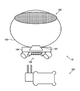
HG. 1 constitutes a schematic perspective view an aerial unit and non anal
unit of a
gaseous matter capture system, according to some embodiments of the invention.
FIG. 2 constitutes a schematic perspective view of the non-aerial unit of a
gaseous matter
capture system, according to some embodiments of the invention.
HG. 3 constitutes a block diagram illustrating possible modules that form an
aerial unit of
a gaseous matter capture system, according to some embodiment of the
invention.
8
CA 03158823 2022-5-18
WO 2021/124332
PCT/IL2020/051301
HG. 4A constitutes a typical phase diagram of CO2 at various temperatures.
HG. 4B constitutes a combo chart depicting sampled CO2 concentrations in the
ambient
air at different altitudes.
HG. 5 constitutes a line graph illustrating the various temperatures and
pressures having
an effect on liquidation or solidification of CO2.
FIGS. 6A & 6B constitute a line graph illustrates the absorption capacities of
sorbents for
carbon capture having high affinity to CO2.
DETAILED DESCRIPTION OF SOME EMBODIMENTS
In the following detailed description, numerous specific details are set forth
in order to
provide a thorough understanding of the invention. However, it will be
understood by those skilled
in the art that the present invention may be practiced without these specific
details. In other
instances, well-known methods, procedures, and components, modules, units
and/or circuits have
not been described in detail so as not to obscure the invention. Some features
or elements described
with respect to one embodiment may be combined with features or elements
described with respect
to other embodiments. For the sake of clarity, discussion of same or similar
features or elements
may not be repeated.
Although embodiments of the invention are not limited in this regard,
discussions utilizing
terms such as, for example, "controlling" "processing," "computing,"
"calculating,"
"determining," "establishing", "analyzing", "checking", "setting",
"receiving", or the like, may
refer to operation(s) and/or process(es) of a controller, a computer, a
computing platform, a
computing system, or other electronic computing device, that manipulates
and/or transforms data
9
CA 03158823 2022-5-18
WO 2021/124332
PCT/1L2020/051301
represented as physical (e.g., electronic) quantities within the computer's
registers and/or
memories into other data similarly represented as physical quantities within
the computer's
registers and/or memories or other information non-transitory storage medium
that may store
instructions to perform operations and/or processes.
Unless explicitly stated, the method embodiments described herein are not
constrained to
a particular order or sequence. Additionally, some of the described method
embodiments or
elements thereof can occur or be performed simultaneously, at the same point
in time, or
concurrently.
The term "Controller", as used herein, refers to any type of computing
platform or
component that may be provisioned with a Central Processing Unit (CPU) or
microprocessors, and
may be provisioned with several input/output (I/0) ports, for example, a
general-purpose computer
such as a personal computer, laptop, tablet, mobile cellular phone, controller
chip, SoC or a cloud
computing system.
The term "Sorbents for carbon capture", as used herein, refers to any material
with higher
affinity to CO2 when compared to other atmospheric gases such as nitrogen and
oxygen and, more
specifically, to diverse range of typically porous, solid-phase materials,
that can accommodate a
wide variety of cations and may include mesoporous silicas, zeolites, metal-
organic frameworks,
etc., wherein these materials have the potential to selectively remove CO2
from large volumes of
air.
The term "Metal¨organic framework (M0Fs)" as used herein, refers to a class of
porous
compounds having low heat capacities and consisting of metal ions or clusters
coordinated
to organic ligands forming ID, 2D, or 3D structures. Because of their small
pore sizes and high
CA 03158823 2022-5-18
WO 2021/124332
PCT/1L2020/051301
void fractions, MOFs are considered a promising potential material for use as
an adsorbent to
capture CO2 and may provide an efficient alternative comparing to traditional
amine solvent-based
methods widely used today. CO2 can bind to a MOF surface through either
physisorption, which
is caused by Van der Waals interactions, or chemisorption, which is caused by
covalent
bond formation. Once the MOF is saturated with CO2, the CO2 would be removed
from the MOF
through either a temperature swing or a pressure swing (a process known as
regeneration). In a
temperature swing regeneration, the MOF would be heated until CO2 desorbs. In
a pressure swing,
the pressure would be decreased until CO2 desorbs.
The term "ZIFs", as used herein, refers to a class of metal-organic frameworks
(M0Fs)
that are topologically isomorphic with zeolites, wherein a particular MOF
named Z1F-8, has a very
high separation factor for hydrogen and carbon dioxide mixtures and a
relatively high specificity
of carbon dioxide over nitrogen. ZIF-8 is also known to be a relatively stable
MOF, thus applicable
over a wide range of temperatures and pressures. ZIFs are composed of
tetrahedrally-
coordinated transition metal ions (e.g. Fe, Co, Cu, Zn) connected by
imidazolate linkers and
having zeolite-like topologies.
The term "inversion layer" as used herein, refers to a layer in the
atmosphere, or as a region
in terms of altitude, in which temperatures tend to stop decreasing with any
further increase in
altitude. While thermal inversion can occur in multiple conditions, it is
common to refer to the
inversion layer as the altitude at which the vertical temperature gradient
reverses, at the top of the
troposphere, sometimes referred to as the tropopause.
According to some embodiments, the present invention discloses a gaseous
matter capture
system comprising a light weight aerial unit configured to be released to the
atmosphere and
11
CA 03158823 2022-5-18
W02021/124332
PCT/1L2020/051301
comprising at least one gas separation means such as a compressor. According
to some
embodiments, said aerial unit may he a high-altitude balloon and may further
comprise controlling,
navigation and steering components. According to some embodiments, said aerial
unit is
configured to capture large amounts of gaseous matter such as carbon dioxide
and to throw it
downwards to a designated non-aerial unit where it may be safely caught.
According to some
embodiments, the aerial unit may be a high-altitude balloon configured for
throwing large
quantities of captured carbon dioxide in order to allow capturing more carbon
dioxide mass in a
single airborne mission hence reducing regular maintenance and ground time
intervals.
According to some embodiments, the separation of the gaseous matter such as
carbon
dioxide from the ambient air can be done using multiple techniques and methods
such as: coolers,
refrigerators, freezers, heat pumps, pressure pumps, compressors, membranes,
separation using
chemical means or catalysts, separation by biological enzymes, etc. Such
techniques and methods
are used to increase the rate at which CO2 is captured from the atmospheric
ambient air.
According to some embodiments, the gaseous matter capture system is configured
to use
the low ambient temperatures and high winds that circulate the surrounding
atmosphere. The
gaseous matter capture system is further configured to prevent dilution of the
carbon dioxide in
the incoming air stream since that, although the air density is lower in the
high troposphere and
the lower stratosphere, the volumetric concentration of carbon dioxide is not
significantly lower
and is almost similar to the levels found at sea level. It is thus applicable
to utilize the above
described carbon capture method at high altitudes above sea level.
According to some embodiments, the gaseous matter capture system is configured
to
collect a gaseous matter directly from the atmosphere (wherein a preferable
gas to be collected
12
CA 03158823 2022-5-18
WO 2021/124332
PCT/1L2020/051301
may be carbon dioxide), for purposes of climate change mitigation and gaseous
matter reuse.
According to some embodiments, the system may be based on carbon dioxide's
phase transition
at low temperatures, such as in ranges of -100 C to -10 C and increased
pressure ranges, such as
between 0.2 Bar to 10 Bar.
According to some embodiments, in order to remove massive amounts of CO2
directly
from the ambient air, without the need for excessive energy input, without the
use of dangerous or
scarce resources, and in a fully scalable manner, the use of high altitude
vehicles equipped with
compressors is suggested.
According to some embodiments, once carbon dioxide has been separated from the
air
flow, it can be stored or utilized further in accordance to various needs or
constrains. For example,
a separated carbon dioxide may be liquefied/solidified and kept in storage
means such as high-
pressure containers, wherein said containers can be made of any known
material, such as
composite carbon fibers, aluminum, polymers etc.
Reference is now made to FIG. 1 which schematically illustrates an aerial unit
100 and
non anal unit 200 of gaseous matter capture system 10. As shown, gaseous
matter capture system
10 may comprise two main units, aerial unit 100 and non-aerial unit 200.
Aerial unit 100 can be,
for example, a high-altitude balloon or any other airborne vehicle, configured
to be flown at high
altitudes, such as altitudes of 5-15km, wherein the standard temperatures at
these altitudes are
typically around -50 C and the air density is approximately 10-30% of those
found at sea level.
According to some embodiments, a high-altitude balloon that operates as an
aerial unit 100,
may be filled with Helium, Hydrogen gas, hot air or any other known substance
used to provide
13
CA 03158823 2022-5-18
WO 2021/124332
PCT/1L2020/051301
aerial lift. According to some embodiments, Aerial unit 100 may be tethered or
untethered to the
non-aerial unit 200.
According to some embodiments, aerial unit 100 may be any known aerial vehicle
or
platform, for example, a powered aircraft (either by internal combustion
engine, jet propulsion,
solar power or electrical power), a gliding aircraft (such as kite, glider
etc.) or an aerostat (such as
an airship, balloon, etc.) According to some embodiments, aerial unit 100 may
be implemented on
an existing aerial vehicle, for example, aerial unit 100 may be retrofitted to
a commercial aviation
plane to be carried upon or implemented with any section of its fuselage,
wings or engines. An
aerial unit 100 retrofitted upon an aerial vehicle may further rely on already
existing systems, for
example, it may use an aircraft's engine built-in compressor as a substitute
to an integrated gas
separation means 102 (disclosed below).
According to some embodiments, gas separation means 102 may comprise a
compressor,
pump or any known pressure increasing device configured to be carried by the
aerial unit 100 and
compress the surrounding air at high flow rates to pressures that are
approximately 5-10 Bar above
the ambient air pressure. According to some embodiments, and as mentioned
above, the separation
of carbon dioxide from the ambient air by the gas separation means 102 can be
achieved by using
various techniques and/or methods such as: refrigeration, heat pumping,
multiple
pumps/compressors, membranal separation, separation using chemical means such
as catalysts,
separation by biological enzymes, etc. Such techniques and methods may be used
to increase the
rate at which carbon is captured from the atmospheric ambient air, reduce the
required energy for
CO2 capturing, etc.
14
CA 03158823 2022-5-18
WO 2021/124332
PCT/1L2020/051301
According to some embodiments, and since strong wind is generally abundant at
high
altitude, the high dynamic pressure caused by said high altitude strong wind
in which the aerial
unit 100 designed to operate, may be exploited for the purpose of separating
CO2 from an airflow
entering separation means 102. For example, gas separation means 102 located
on an aerial unit
100 may use different types of membranes in order to filter the incoming
airflow and produce
filtered air having an increased CO2 concentration with regard to Nitrogen or
other gases'
concentration. Said increased CO2 concentration may be high over an order of
magnitude (x10)
with regard to the CO2 concentration in the ambient airflow, hence, harnessing
the wind for the
sake of said gaseous matter separation may significantly increase the
efficiency of said process by
reducing the need to comperes the incoming airflow.
According to some embodiments, since the gas separation means 102 of aerial
unit 100 are
configured to operate at high altitude, much of the energy generally used to
compress ambient air
at ground altitude is generally unneeded. According to some embodiments, after
being separated
from its CO2, the compressed air may be further utilized by using its
potential stored energy. For
example, the potential energy stored within the compressed air may be used
directly to compress
further airflow or indirectly to power various electrical/mechanical systems,
thus leading to further
energy/weight savings.
According to some embodiments, in order to increase carbon dioxide capture
efficiency,
the aerial unit 100 may utilize multiple gas separation means 102 in parallel,
for example, gas
separation means 102 may be multiple compressors aliened in series/in several
stages in order to
provide an efficient compression and separation of gaseous matter.
CA 03158823 2022-5-18
WO 2021/124332
PCT/1L2020/051301
According to some embodiments, designated substances may be used for CO2
capture or
CO2 separation and may be implemented within gas separation means 102 in order
to increase the
amount of CO2 available for separation. Said substances may be, for example,
MOFs, ZIFs, or
any other known sorbents for carbon capture and may be arranged in the form of
thin films and
produced by various chemical processes such as nano deposition techniques such
as ALD, CVD,
PVD, Glancing Angle Deposition, etc.
According to some embodiments, at least one storage means 106, for example, a
compressed gas tank/s, is/are configured to store the separated gaseous matter
such as CO2 in a
liquid, solid or gas form after it has been extracted from the compressed air
flow.
According to some embodiments, in order to maximize the CO2 extraction
efficiency by
aerial unit 100 and to allow maximum collection of gaseous matter given
limited resources and
constrains and in order to allow for more airborne time before the need of
aerial unit 100 to land,
the gaseous matter capture system 10 may be configured to release full gas
tanks designed to safely
land on a designated non-aerial unit/s or on predefined ground/watery
locations for further
utilization.
According to some embodiments, the gaseous matter capture system 10 further
comprises
a designated mechanism (not shown) configured to enable a controlled release
of at least one
storage means 106 that may be a compressed gas tank. For example, the
controlled release means
may be configured to disconnect storage means 106 after it has been filled
with gaseous matter in
order to eliminate excess weight from the airborne vehicle. According to some
embodiments,
storage means 106 is configured to be released and fall downwards to a pre-
designated non-aerial
unit, where it may be safely caught and collected.
16
CA 03158823 2022-5-18
WO 2021/124332
PCT/1L2020/051301
According to some embodiments, storage means 106 may be a free-falling tank's,
configured to be thrown by/released from the aerial unit 100, using the
aforementioned designated
release mechanism, or alternatively, fall in a guided manner. Storage means
106 may include
utilization of parachutes, gliding wings, propellers, gas injections or jet
thrusters in order to provide
trajectory correction ability or any other known steering/navigation means.
According to some embodiments, controller 104 is further configured to provide
general
operational control of the gaseous matter capture system 10. According to some
embodiments,
controller 104 may be positioned upon the aerial unit 100, upon the non-aerial
unit 200, or may be
located elsewhere, for example, on a remote server or as part of cloud
computing platform.
According to some embodiments, controller 104 is configured to provide
navigation control to
aerial unit 100, wherein said navigation control may be conducted
automatically or manually by a
user monitoring the operation of the gaseous matter capture system 10.
According to some embodiments, the aerial unit 100 may further comprise
propulsive/steering means (not shown) that can be any known propulsive
component configured
to provide a controlled aerial deployment of the aerial unit 100. According to
some embodiments,
controller 104 may control the propulsive/steering means that may be jet
thrusters, rocket
propulsion, flaps, propeller of any sort or any other known means of
propulsion_
According to some embodiments, the gaseous matter capture system 10 further
comprises
communications means (not shown) configured to provide a reliable and fast
communication track
between the aerial unit 100 and the non-aerial unit 200. For example, a
communication system that
may be controlled by the controller 104 may provide navigation commands to the
aerial unit in
17
CA 03158823 2022-5-18
WO 2021/124332
PCT/1L2020/051301
accordance with various needs or restrains and may be operated either
automatically or manually
by a user monitoring the operation of the gaseous matter capture system 10.
According to some embodiments, the gaseous matter capture system 10 further
comprises
an energy source 108 that may be a power reservoir/battery, a hydrogen
reservoir (that may
simultaneously be used for lift purposes), solar panels/paints/sheets, wind
turbines (in order to take
advantage of the surrounding strong wind), nuclear power generators, thermal-
nuclear power
sources in conjunction with thermoelectric elements, etc. According to some
embodiments, a
tethered wire connected to the ground, the non-aerial unit 200 or to another
airborne vehicle may
provide the energy needed for the operation of aerial unit 100. According to
some embodiments,
the energy sources used to provide power to the gaseous matter capture system
10 are configured
to be carbon neutral or close to it, in order not to contradict the main
purpose of carbon dioxide
extraction.
According to some embodiments, aerial unit 100 may be configured to be
deployed in a
relative position that has the ability to provide constant or near constant
energetical availability, or
has the ability to provide aerial unit 100 with improved gaseous matter
capturing conditions. this
can be achieved by adaptively changing the altitude/position of aerial unit
100 in order to utilize
different wind directions or solar radiation conditions. According to some
embodiments, in order
to change the relative deployment of aerial unit 100, propulsion and/or
navigation and steering
means may be used as previously disclosed.
According to some embodiments, the final product of the gaseous matter capture
system
10 may be high purity carbon dioxide intended for either storage or reuse in
applications such as
agriculture, food industry, research, synthetic near emission neutral fuels
manufacturing, etc.
18
CA 03158823 2022-5-18
WO 2021/124332
PCT/1L2020/051301
Reference is now made to FIG. 2 which schematically illustrates a non-aerial
unit 200 of
gaseous matter capture system 10 (previously disclosed). As shown, a
designated landing area 202
that may be any kind of capturing platform (such as a trampoline), is
configured to provide a safe
area for high velocity, large mass falls. The fast falling storage means 106
may land upon the
landing area 202 to be further collected by any mechanical, robotic or manual
means (not shown).
According to some embodiments, the non-aerial unit 200 may include a
designated facility
204 configured to provide either maintenance requirements for aerial unit 100
and/or processing
of the at least one storage means 106 after it has been loaded with gaseous
matter and captured by
the landing area 202.
According to some embodiments, the non-aerial unit 200 may be located on the
ground or
on a body of water floating platform, alternatively, the non-aerial unit 200
may be located upon a
moving platform such as any kind of marine vessel or terrestrial vehicle.
According to some
embodiments, After the capturing of storage means 106 by the landing area 202
and the delivery
of storage means 106 to the designated facility 204, industrial procedures
that may be either
chemical and/or mechanical may utilize the collected gaseous matter for
further storage or use.
According to some embodiments, non-aerial unit 200 may further comprise
docking area
206 configured for either marine vessels or terrestrial vehicles, in order to
enable the transfer of
the captured gaseous matter to another location.
Reference is now made to FIG. 3 which illustrates a block diagram disclosing
possible
modules that form aerial unit 100. As shown, energy module 300 may be a power
reservoir such
as a battery, hydrogen-based fuel cell, solar panel/paint/sheet, wind turbine,
nuclear generator or
19
CA 03158823 2022-5-18
WO 2021/124332
PCT/1L2020/051301
any other power source that does not emit greenhouse gasses or generate
reduced levels of
greenhouse gasses.
According to some embodiments, control module 302 is further configured to
provide
general operational control of the gaseous matter capture system 10 and may
comprise a controller
positioned upon the aerial unit 100, upon the non-aerial unit 200 (not shown),
or may be located
elsewhere, for example, on a remote server or as part of cloud computing
platform. According to
some embodiments, control module 302 is configured to generate
navigation/steering commands
in order to control aerial unit 100, wherein said navigation/steering control
may be conducted
automatically or manually by a user monitoring the operation of the gaseous
matter capture system
10. According to some embodiments, control module 302 is configured to monitor
the various
parameters and operations that are part of the gaseous matter capture system
10's activity.
According to some embodiments, gas separation module 304 is configured to
enable the
separation of gaseous matter such as carbon dioxide from the ambient air which
may be done using
multiple techniques and methods such as: single/multiple pumps or compressors
(or any known
pressure increasing device), membranes, separation using chemical means or
catalysts, separation
by biological enzymes, etc.
According to some embodiments, gaseous matter storage module 306 is configured
to
store a liquefied/solid or high pressurized gaseous matter such as carbon
dioxide in at least one
high-pressure container (storage means 106 previously disclosed), wherein said
container may be
a free-falling container configured to be thrown by/released from the aerial
unit 100, using the
aforementioned designated release mechanism, or, alternatively, fall in a
guided manner.
According to some embodiments, said high-pressure container may include
utilization of
CA 03158823 2022-5-18
WO 2021/124332
PCT/1L2020/051301
parachutes, gliding wings, propellers, gas injections, jet thrusters or any
other known
steering/navigation means in order to provide trajectory corrections ability_
According to some embodiments, navigation module 308 is configured to provide
navigation abilities to the aerial unit 100 and may comprise designated
navigation components
such as GPS, altitude/velocity sensors, etc. in order to determine the exact
location, height and
relative position of the aerial unit 100. The navigation module 308 may
further utilize a database
regarding the wind regime at a certain location and altitude in order to adapt
aerial unit 100's
operation to changing weather conditions. According to some embodiments,
navigation module
308 may be a separated module of may be integrated within control module 302.
According to some embodiments, propulsion module 310 is configured to propel
the aerial
unit 100 to a desired location/altitude, wherein the propulsion of aerial unit
100 may be conducted
using jet thrusters, rocket propulsion, flaps, propellers of any sort or any
other known means of
propulsion.
Reference is now made to FIG. 4A which illustrates a phase diagram depicting a
carbon
dioxide's phase transition at relatively low temperatures and relatively high
pressures_
According to some embodiments, in order to liquefy the gas at a temperature of
approximately -55 C, the required pressure should be approximately 6
atmospheres. Due to the
said relatively high liquefaction pressure, gas liquification performed at
high altitude may
represent a challenge for a carbon capture procedure. As shown, the separation
of carbon dioxide
can be done by liquefaction or solidification. According to some embodiments,
reaching any point
below the triple point temperature of approximately -56 C and having
sufficiently high pressures,
will result in carbon dioxide solidification_ Conversely, increasing the
pressure at temperatures
21
CA 03158823 2022-5-18
WO 2021/124332
PCT/1L2020/051301
above the triple point, for example by applying pressures of 6-10 Bar, will
result in the liquefaction
of carbon dioxide.
According to some embodiments, any combination of temperature and pressure
within the
limits that enable carbon dioxide liquefaction/solidification may be used
during the operation of
gaseous matter capture system 10.
According to some embodiments, since in high altitude the air density is
approximately
one third of the ambient air at sea-level, at least one stage of compression
may be used in order to
increase the incoming air pressure from said typical pressure at high altitude
(0.2-0.8 Bar) in order
to reach the range enabling carbon dioxide solidification/liquefication. The
required increase in
pressure may be multiplied by a ratio of 3 to 50 at the end of all compression
stages in order to
reach said typical transition pressure of 6-10 Bar.
According to some embodiments, when said pressure levels are reached, and
given an
appropriate temperature (approximately -55 C), a liquefaction of the CO2
contained within the
processed incoming air is likely to follow. Alternatively, further reducing
the temperature by 40 C
-70 C while exposing the incoming air to sufficiently high pressure will
mainly result in
solidification of the CO2 contained within the incoming air.
According to some embodiments, pressure or temperature changes may be done
during a
single compression/separation stage or during multiple stages. According to
some embodiments,
when using multiple compression/separation stages as part of the process of
carbon dioxide
capturing disclosed above, the coefficient of performance in cooling that
represents some of the
energetic efficiency, may be higher.
22
CA 03158823 2022-5-18
WO 2021/124332
PCT/1L2020/051301
Reference is now made to FIG. 4B which illustrates a combo chart depicting
sampled CO2
concentrations in the ambient air at different altitudes (9-101cm) and various
temperatures. As
shown, the volumetric concentration of CO2 remains almost the same at high
altitudes, namely
slightly under 400 ppm when compared to 411 at sea level. This may be due to
the fact that the
strong winds provide constant airflow and prevent dilution of CO2.
According to some embodiments, the high altitude that aerial unit 100 is
configured to be
located at, represents a tradeoff between low temperatures that allow the use
of less energy
consumption to reach CO2 phase transition, along with low overall pressures,
which increase the
energy consumption needed to reach a desired pressure in order to achieve CO2
phase transition
by either liquefaction or solidification. As noted above, the CO2
concentration within the ambient
air at different altitudes remains approximately similar, and does not
significantly change the
efficiency of the CO2 separation process.
According to some embodiments, and as previously shown, compressing the
incoming air
entering the separation means 102 located on aerial unit 100 at high altitude
in order to reach
pressures of 6-10 bar results in CO2 separating from the incoming airflow and
stored in a
liquid/solid form inside storage means 106. Considering the gas molar
volumetric concentration
(22.4 liters per mole) in standard conditions, in high altitude where the
temperatures range is
approximately -50oC and the pressure is about 0.25 bar, the gas molar
volumetric concentration is
-70 liters per mole (22.4 L/mole, multiplied by (223 C /273 C) for the
temperature correction and
by (101.3KPa/26.5KPa) for the pressure correction results in 70 Umole).
According to some embodiments, at a concentration of 400 ppm CO2, and given a
molar
mass of 44 Wmole, there is a need to compress 70*2500 (2500 being the
reciprocal of 400 ppm)
23
CA 03158823 2022-5-18
WO 2021/124332
PCT/1L2020/051301
liters to get to one mole, (or 44 grams). According to the above, in order to
produce one ton of
CO2, there is a need to compress approximately 4 million cubic meters of
ambient air_
Nowadays, simple and inexpensive compressors reach flow rates measured at
several cubic
feet per minute, or several liters per second. According to that, in order to
reach a level of a metric
ton per day would require several compressors in parallel_
According to some embodiments, it is possible to compress the air travelling
at a typical
high-altitude wind of 1001an/h through an orifice having a certain diameter,
in order to reach high
capacity, for example, 4 million m3 of flow rate within less than a day.
According to some embodiments, in order to introduce an overall solution to
climate
change, and assuming that each aerial unit 100 is able handling around one
metric ton of CO2
captured per day, a hypothetical gaseous matter capture system 10 will need to
be comprised of 54
million aerial units 100 in order to capture all excess CO2 introduced into
the atmosphere in 2018.
Considering that each aerial unit 100 has an annual price tag of $100K, the
complete solution of
an annual global CO2 emissions capture will cost around $5,000B. this
estimation is not only far
lower than any known alternative, but significantly lower than the expected
economic damage
associated with climate change. For reference, the International Panel on
Climate Change (IPCC)
stated that it needs $13,000B to reverse the increasing trend of carbon
emissions and lower it by
10 Billion Tons of CO2. Meaning over twice the cost for less than half the
result.
Reference is now made to FIG. 5 which illustrates a line graph depicting
temperature
differences affecting phase transition of CO2 based on standard US atmospheric
data. More
particularly, the line graph represents the difference in temperatures
affecting the initiation of
24
CA 03158823 2022-5-18
WO 2021/124332
PCT/1L2020/051301
phase transition of captured CO2 in accordance with the decrease in
temperatures associated with
increased altitude and lower/higher pressures.
According to some embodiments, at the inversion layer, (not shown, typically
at altitudes
of 11-13 kilometers above sea level, but potentially varying beyond these
numbers in equatorial
or polar regions), the required temperature difference decreases along all 3
lines, and hence the
inversion layer represents the ideal altitude for performing high altitude gas
separation. According
to some embodiments, the ambient temperature at said inversion layer is
approximately -50 C, and
the ambient pressure is approximately 0.3 Bar. This means that to separate CO2
by solidifying it,
a reduction of approximately 40 C is required as seen in FIG. 4 showing the
freezing point of CO2
is approximately -90 C at 0.3 Bar.
According to some embodiments, and as part of the assumption that the ideal
height for a
gas separation process is at the inversion layer or its vicinity, there are
some additional parameters
that may be taken into account. Due to the increased pressure of the ambient
air found in said
inversion layer, various methods of gaseous matter separation using physical
and chemical
separation procedures may be enabled. For example, the use of molecular sieves
such as Metal
Organic Frameworks MOF, Zeolites or other designated substances may benefit in
terms of gas
separation efficiency from higher pressures occurring at the inversion layer
or its vicinity.
According to some embodiments, the temperature differences required at a given
altitude
in order to perfortn gas separation procedure according to the standard US
atmosphere data are
disclosed:
According to some embodiments, an estimated calculation of either cooling the
air to CO2
freezing temperature or compressing it to liquid/solid form is provided as
follows: Cooling
CA 03158823 2022-5-18
WO 2021/124332
PCT/1L2020/051301
incoming air as part of the operation of the gaseous matter capture system 10
requires low air
temperature with sufficient CO2 mass. For example, To cool mcoz = 100Kg, by
approximately
40 K lower than the ambient air temperature, will require Mtor car * (40 K),
where
cir-0.71K1 /KG, and thus the energy cost is 7 = 106KJ, or in a period or over
a 12 hours day,
160KW. In addition, the enthalpy of sublimation (latent heat) is -590KJ/Kg,
meaning that an
additional 1.5KW are required for the phase transition, though this may be
considered negligible
compared to the total required cooling energy.
According to the second law of thermodynamics, the cooling efficiency is
limited such that
in order to remove -160KW of heat from the certain mass of air, and giving an
ideal coefficient
re
of performance of CoP =¨ '--- 4.5 (given a freezing temperature of -90 C, or
183 K, and a
Th¨Tc
starting temperature of -50 C, or 223 K, put into the equation as Tc for the
lower temperature and
Th for the higher temperature), the suggested calculation may, for every watt
used for heat
removal, remove approximately 4.5W from the cooled air by a single stage
cooling at a maximal
temperature difference, wherein multiple cooling stages will increase the
efficiency of said cooling
process in accordance with a decrease in temperature differences. Assuming
that the average
multiple stage cooling requires approximately 2W of power, the result is a
required energy of
-80KW.
According to some embodiments, the above-mentioned power requirements may be
achieved by harnessing the surface area of areal unit 100. For example, and
using a technology of
commercially available plastic based solar energy films, a power generation
density of 100Wp/m2
may be achieved by an aerial unit 100 having approximately 10-meter radius and
approximately
200m2 of surface area available at a given moment for power generation. Said
surface area covered
26
CA 03158823 2022- 5- 18
WO 2021/124332
PCT/1L2020/051301
with solar energy films may produce approximately 40KW of power that
represents marginally
sufficient energy at very high COPs (coefficient of performance).
According to some embodiments, the air processed by the areal unit 100 may be
cooled
down to the freezing temperature of CO2 and the captured CO2 may be stored in
storage means
106_ CO2 may be frozen by lowering its temperature to a range of -80 C to -100
C depending on
the surrounding air pressure. Since the ambient temperature at high altitudes
where the areal unit
100 is configured to operate is around -50 C, the potential cooling component
of areal unit 100
can work typically at a Carnot efficiency of -3.5 to -6.4 [COP<Tc/(Th-Tc) when
the air pressure
is lower and resulting phase transition is at -100 C (thus putting the numbers
in units of K into
the equation for COP, as 173 K for the lower temperature and 223 K for the
higher temperature),
the resulting COP is - 173/(223-173)=3.46. and when the air pressure is higher
and resulting
required temperature is -80 C or 193 K - 193/(223-193)=6.43].
According to some embodiments, in order to overcome the latent sublimation
heat that
may be produced as part of the air-cooling procedure, there is a need to
invest at least 2001 per
each gram of CO2, meaning that for a rate of one gram per second, there is a
need to remove 200W
of heat in order to overcome the produced latent heat. In accordance to the
above, the upper limit
of CO2 freezing rate (given a 1KW power input) would be 17.5g per second
(756Kg over a 12
hours' period), neglecting all other power needs. When dismissing 20% of this
approximate
efficiency as a reasonable assumption, we get that a 1KW of power input is
sufficient to allow
phase transition of approximately 3 grams CO2 per second.
According to some embodiments, further capturing techniques using substances
having
high affinity to CO2, that include, among others, Metal Organic Frameworks
(M0Fs) may be used
27
CA 03158823 2022-5-18
WO 2021/124332
PCT/1L2020/051301
as part of the operation of areal unit 100. Using such techniques will
increase the tendency of CO2
to nucleate on them and require less air volume to be cooled_
Reference is now made to FIGS. 6A & 6B which illustrates a line graph
depicting
absorption capacity of sorbents for carbon capture with high affinity to CO2
according to some
embodiments of the invention_ As shown, FIG. 6A depicts the adsorption
capacity and absorption
dynamics of CO2 in Zeolites with regard to various pressures. FIG. 6B depicts
a particular MOF
compound (ZIF-8) absorption property of CO2 at different temperatures and
pressures. The results
depicted on FIGS. 6A & 6B suggest that when using the aforementioned
materials, the effect of
decreasing temperatures is more prominent than variable pressure values with
regard to the
aforementioned substances' absorbing efficiency of CO2. In other words, the
aforementioned
substances ability to absorb CO2 increases dramatically when the temperature
drops down to the
inversion layer average temperature, as previously disclosed.
According to some embodiments, by using other substances and in other
circumstances,
various pressure swings required to adsorb and desorb a certain separated gas
may be more
prominent. In such cases and in others, deploying areal unit 100 at lower
altitude with increased
ambient temperature and higher air pressure, or alternatively, deploying areal
unit 100 at higher
altitude, typically with similar temperature yet with lower air pressure, may
have a critical effect
on the absorption efficiency of the gas separation process conducted by the
areal unit 100. Hence,
for some applications and embodiments, the gas separation process may be
conducted at ambient
temperature as high as approximately -10 C and at a typical altitude of
approximately 5 km above
sea level. Alternatively, and according to some embodiments, in higher
altitude of approximately
15 km, the pressure may drop to approximately 0_2 Bar while still allow a gas
separation process
28
CA 03158823 2022-5-18
WO 2021/124332
PCT/1L2020/051301
with a benefit of decreasing the required energy for pressure reduction as
part of desorbing
processes_
Although the present invention has been described with reference to specific
embodiments,
this description is not meant to be construed in a limited sense. Various
modifications of the
disclosed embodiments, as well as alternative embodiments of the invention
will become apparent
to persons skilled in the art upon reference to the description of the
invention. It is, therefore,
contemplated that the appended claims will cover such modifications that fall
within the scope of
the invention.
29
CA 03158823 2022-5-18