Note: Descriptions are shown in the official language in which they were submitted.
CA 03141127 2021-11-17
WO 2020/243320
PCT/US2020/034945
PROCESS FOR THE FACILE ELECTROSYNTHESIS OF
GRAPHENE FROM CO2
CROSS-REFERENCE TO RELATED APPLICATIONS
[0001] This application claims the benefit of U.S. Provisional Nos.
62,938,135, filed on
November 20, 2019, 62/890,719, filed on August 23, 2019, and 62/853,473, filed
on May
28, 2019, the entire contents of each of which are incorporated herein by
reference.
FIELD OF THE INVENTION
The present invention relates to the production of graphene from CO2 through
electrolysis and exfoliation processes. The exfoliating step produces graphene
in high yield
than thicker, conventional graphite exfoliation reactions. CO2 can be the sole
reactant used to produce the valuable product as graphene. This can
incentivize
utilization of CO2, and unlike alternative products made from CO2 such as
carbon
monoxide or other fuels such as methane, use of the graphene product does not
release this greenhouse gas back into the atmosphere.
BACKGROUND OF THE INVENTION
[0002] Graphene has unique properties that are useful for a variety of
applications.
However, the synthetic costs and the challenge to isolate the graphene product
in its native
two dimensional structure lead to the high current cost of graphene, valued at
approximately
Si million per ton. See Price and Market of Materials, Carbon XPrize Standards
Data
Summary Set, Draft V1.2, (Sept. 12, 2017)).
[0003] Graphene has a high surface area, high thermal and electrical
conductivity,
.. strength, surface tailorability, and high charge carrier conductivity that
makes it uniquely
suitable for energy storage and electronics. See, e.g., Coro et al., Front.
Mat. Sci., 2019, 13,
1
CA 03141127 2021-11-17
WO 2020/243320
PCT/US2020/034945
23; Agudosi et al., Grit. Rev. Mat. Sci., 2019, 1040-8436, 1; Bai et al.,
Electrochem.
Energy Rev., 2019, doi.org/10.1007/s41918-019-00042-6; and Zhang et al., Adv.
Sci., 2017,
1700087, 4.
[0004] The ability of graphene to carry plasmons allows it to strongly
interact with light
in a non-linear fashion and act both as a transducer and transmitter in
optoelectronics.
Graphene's 2D honey-comb lattice sp2 crystal structure possess extremely high
intrinsic
charge mobility (250,000 cm2/Vs), a high specific surface area (2630 m2/g),
high thermal
conductivity (5000 W/mK), high Young's modulus (1.0 TPa), and high optical
transmittance
(97.7%).
[0005] Methods to produce graphene include thermal annealing (see, e.g., Li
et al., J.
Nanomat., 2011, 2011, 319624), unzipping nanotubes (see, e.g., Tanaka et al.,
Sci. Rep.,
2015, 5, 12341), solvothermal and thermal decomposition (see, e.g., Singh et
al., Int. J.
Nanosci., 10, 39; Berger et al., J. Phys. Chem. B, 2004, 108, 19912), ball-
milling and
chemical exfoliation (see, e.g., Del Tio-Castillo et al., Nano Res., 2014, 7,
963; Liu et al.,
.. Chem. Eng. J., 2019, 355, 181), and chemical vapor deposition (CVD) (see,
e.g. Shukla et
al., Appl. Phys. Rev., 2019, 6, 021331; Azam et al., ECS J Solid State Science
Technology,
2017 6(6) M3035; Lee et al., RSC Adv, 2017, 7, 15644; and Zhang et al.õ Adv.
Sci., 2017,
1700087, 4).
[0006] Chemical vapor deposition (CVD) is a popular method to produce
graphene
from a variety of organometallics or other carbon sources using transition
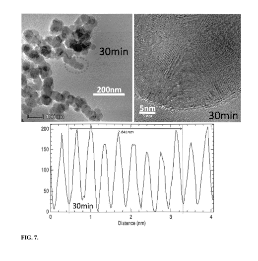
metal catalysts.
However, conventional CVD can have a massive carbon footprint of over 600
tonnes of
CO2 per tonne of nano-carbon produced (see, e.g. Khanna et al., J. Ind.
Ecology, 2008, 12,
394).
[0007] In a 2003 paper investigating processes detrimental to Li-ion
battery anodes, it
was noted that electrochemical alkali ion intercalation could lead to peeling
off of layers
from a graphite anode (see, e.g., Buqa et al., US DOE Tech Rep. [5_6]ETDE-CH-
0301, 2003,
63; also see Spahr et al., J. Electrochem. Soc., 151, 2004, 181).
[0008] In 2007, the observation of one-atom thick graphene layers by
electrochemical
exfoliation was observed (see, e.g., Penicaud et aL, Compos. Sci. Teehnol.,
67, 2007,
2
CA 03141127 2021-11-17
WO 2020/243320
PCT/US2020/034945
795; Man sour et al., Carbon, 45, 2007, 1651; and Valles et al., J. Am. Chem.
Soc., 130,
2008,15802).
[0009] Electrochemical exfoliated graphene prepared from graphite is of
increasing
interest today, and is often mechanistically interpreted as an anodic process
in which
intercalated ions between the graphite layers are oxidized, forming gases
which break the
weak interlayer Van der Waals bonds, and release thin single or multi-layered
graphene
sheets into the electrolyte (see, e.g., Hashimoto et al., Electrochem. Comm.,
104, 2019,
106475; Xia et al.. Nanoscale, 11, 2019, 5265; Bakunin etal., Inorg. Mat.:
Appl. Res., 10,
2019, 249; and Khahpour et al., Appl. Energy Mai., 2, 2019, 4813). In 2017, it
was observed
.. that compression of graphite flakes prior to exfoliation, such as using
graphite powder
confined by wax coating could increase the yield of graphene (see, e.g.. Wang
et al., Appl.
Mat. Interfaces, 9, 2017, 34456).
[0010] A low carbon footprint carbon nanomaterial may be produced from a
molten
carbonate by electrolysis, at low cost and using CO2 as a reactant, for
example as a C2CNT
(CO2 to Carbon Nanotube) synthesis. However, technical challenges have
prevented scale-
up of the process and the nanomaterial remains scarce. While examples of
carbon nanotubes
(CNTs) prepared by C2CNT synthesis have been termed "straight," each example
of
synthesized, grouped, CNTs shown was visibly entangled, and twisted or hooked,
although
less twisted than CNTs denoted "tangled". Entangled and twisted CNTs tend to
agglomerate
and are it is difficult therefore to disperse them homogeneously in a
composite. In the
C2CNT synthesized examples "straight" referred specifically to CNTs containing
less sp3
bonding amongst carbons defects, and "tangled" CNTs contain more sp3 defects.
Example
processes for producing carbon nanomaterials from molten carbonates by
electrolysis are
disclosed in, for example, Licht et al., J. CO2 Utilization, 2017, vol. 18,
335-344; Nano
Lett., 2015, vol. 15, 6142-6148; Materials Today Energy, 2017, 230-236; Data
in Brief,
2017, vol. 14, 592-606; Scientific Reports, Nature, 2016, vol. 6, 1-10; ACS
Cent. Sci., 2015,
vol. 2, 162-168; RSC Adv., 2016, vol. 6, 27191-27196; Carbon, 2016, vol. 106,
208-217;
Energy Conyers. Manag., 2016, vol. 122, 400-410; J. CO2 Utilization, 2017,
vol. 18, 378-
389; J. CO2 Utilization, 2017, vol. 18, 335-344; J. Phys. Chem. Lett.,. 2010,
vol.1, 2363-
2368; J. Phys. Chem. C, 2009, vol. 113, 16283-16292; J. CO2 Utilization, 2019,
vol. 34,
303-312; Adv. Sustainable Syst., 2019, vol. 3, 1900056; and Mater. Today
Sustainability,
2019, vol. 6, 100023; U.S. Patent Nos. 9,758,881 and 9,683,297, U.S.
Publication No.
3
CA 03141127 2021-11-17
WO 2020/243320
PCT/US2020/034945
2019/36040, and International Publication Nos. WO 16/138469, WO 18/093942, and
WO
18/156642.
[0011] There remains, however, a need for a convenient and facile low
cost, low carbon
footprint synthesis of graphene.
SUMMARY OF THE INVENTION
[0012] The present invention describes a novel facile electrosynthesis of
graphene at
low cost from CO2. The process involves (i) performing electrolysis between an
electrolysis anode and an electrolysis cathode in a molten carbonate
electrolyte to generate
carbon nanomaterial on the cathode; and (ii) electrochemically exfoliating the
carbon
nanomaterial from a second anode to produce graphene.
[0013] The electro-synthesized carbon platelets are nano-thin, promoting
higher
graphene yields than observed using thicker, conventional graphite exfoliation
processes. CO2 can be the sole reactant used to produce the graphene product.
Utilization of CO2 as the sole reactant produces graphene as a low carbon
footprint
product. This incentivizes utilization and consumption of CO2 and, unlike
alternative
products made from CO2 such as carbon monoxide or other fuels such as methane,
use of the graphene product does not require combustion and does not release
this
greenhouse gas back into the atmosphere. The cost of the electrochemical
processes
described herein is low and carbon dioxide is consumed in the formation of the
graphene.
Prior to the work described herein, it was considered that graphene could only
be mass
produced with a high carbon footprint and at high cost. CO2 electrolysis in
molten carbonate
production of carbon platelets readily scales upward linearly with the area of
the electrolysis
electrodes, facilitating larger scale synthesis of graphene.
[0014] The graphene produced by the processes described herein typically
exhibits a
relatively small lateral dimension (on the order of about 2 to 8 p.m). This
lateral size is
beneficial, for example, for the use of graphene as a lubricant, in battery
anodes, and in
graphene admixture applications. Larger lateral dimensions, however, may be
expected with
further variations in the electrochemical growth parameters, including, for
example,
4
CA 03141127 2021-11-17
WO 2020/243320
PCT/US2020/034945
electrolysis duration, current density, temperature, electrode and electrolyte
composition,
and would expand the utility of the molten carbonate electrolysis processes
described
herein.
[0015] Electrosynthesized carbon platelets and other non-CNT graphene
layered
morphologies (such as carbon nano-onions) comprising nano graphene layers in
unique
arrangements may be synthesized by the processes described herein. The
inventor has
discovered the molten carbonate electrosynthesis of two classes of carbon nano-
products. A
first class is formed when a transition metal nucleating agent is included in
the electrolysis
and produces carbon nanotubes and carbon nanofibers. In the present invention,
a second
class is formed when transition metal nucleating agents are suppressed or
excluded from the
electrolysis, yielding unique nano structures including, for example, nano-
platelets, nano-
onions and nano-scaffolds. Each of the nano-structures described herein
contains layered
graphene and may be exfoliated to form graphene plates.
[0016] Without being bound to any particular theory, the present inventor
theorizes that
carbon nanotubes are thermodynamically more stable and grow more readily than
other
graphene layered nanomaterial products. One ramification of this stability is
that CNTs
display the highest material strength of any material measured to date. See
e.g., Yu, et al.,
Science, 287 (2000) 637-640 and Chang et al., ACS Nano 4 (2010) 5095-5100.
Hence,
CNTs provide a low energy route to a specific carbon nanomaterial product.
[0017] Nanotube growth in molten carbonate is electrocatalytically
facilitated by
transition metal nucleation. When the nucleation is disrupted by, for example,
suppression,
exclusion and/or inhibition, alternative carbon nano morphologies are observed
to occur. In
order to support the dominant growth of unique graphene layered carbon nano-
nano-
scaffolds, an experimental set of conditions have been identified that
discourage the
transition metal nucleation route. For example, several electrolysis
conditions are described
herein that reliably and consistently inhibit CNT nucleation and promote
growth of other
graphene layered based carbon nano-materials, even in the presence of the
transition metal
nucleation agents, such as Ni, Cr and Fe.
[0018] The first is the direct cathodic deposition exclusion of
transition metals that can
be in the electrolysis system (e.g., the deposition of transition metals onto
the cathode is
5
CA 03141127 2021-11-17
WO 2020/243320
PCT/US2020/034945
inhibited, suppressed or prevented). For example, this can be achieved by
selecting
electrolytic conditions which suppress the solubility of transition metal
nucleating agents in
the electrolyte. The lowered solubility minimizes their concentration in the
electrolyte or
near the cathode surface to inhibit their diffusion and inhibit the
development of nucleation
seeds required for CNT growth. Examples of these physical chemical conditions
include,
for example, (i) the use of nucleating metals, such as iron, in binary
carbonates (i.e., a
mixture of carbonates such as lithium carbonate in combination with potassium
and/or
sodium carbonate, instead of pure lithium carbonate) in which the nucleating
metals are less
soluble, and (ii) metal cation concentrations which are in equilibria balance
with oxides; an
increase in one, diminishes the solubility of the other, and therefore
addition of oxide to the
carbonate electrolyte will diminish the solubility and availability of the
transition metal
nucleating agents.
[0019]
Other physical chemical conditions to favor layered graphene morphologies over
CNTs include: (i) a decrease in the electrolysis temperature, (ii) a decrease
in the
concentration of lithium in the molten carbonate electrolyte replaced by an
increase in larger
than lithium species, and with decreased lithium concentration even at higher
temperatures,
and (iii) conditions of higher electrolysis current density. Consistent with
these
observations are the mechanistic implications inhibiting nucleation that a
decrease in
temperature will decrease the rate of carbonate mass transport to a point
source for
nucleation, which will have a greater inhibiting effect than a wide area
diffusion to a
growing nano carbon structure (i.e., less material is provided for reduction
and carbon
growth). A larger cation than lithium will face a larger energy barrier when
attempting to
permeate the nucleation site and growing CNT walls to provide needed charge
compensation during the ongoing growth process. Similarly, the greater mass
transport
required at higher current density will favor the two-dimensional diffusion
consistent with
the scaffold's largely planar growth, rather than the point source diffusion
consistent with a
nucleation point growth process. Each of these techniques can be used alone or
in any
combination to inhibit, suppress, or prevent transition metal nucleation.
[0020]
According, in one aspect, the present invention relates to a method for
producing
a graphene carbon nanomaterial. In one embodiment, the method comprises:
6
CA 03141127 2021-11-17
WO 2020/243320
PCT/US2020/034945
(i) performing electrolysis between an electrolysis anode and an
electrolysis
cathode in a molten carbonate electrolyte to generate carbon nanomaterial on
the cathode;
and
(ii) electrochemically exfoliating the carbon nanomaterial (for example,
from a
second anode) to produce graphene.
[0021] In one embodiment of any of the methods described herein, step (i)
is performed
without a transition metal on or adjacent to the surface of the cathode.
[0022] In one embodiment of any of the methods described herein, the
electrolysis
anode and molten carbonate electrolyte in step (i) do not include a transition
metal. In
another embodiment of any of the methods described herein, the electrolysis
anode,
electrolysis cathode, and molten carbonate electrolyte in step (i) do not
include a transition
metal that is molten above the electrolyte melting point, such as zinc, tin,
lead, cadmium,
mercury or aluminium.
[0023] In another embodiment, the electrolysis is performed in the
absence of an oxide,
such as an alkali metal oxide (e.g., lithium oxide).
[0024] In one embodiment of any of the methods described herein, the
electrolysis in
step (i) is performed in the absence of a transition metal. In one embodiment
of any of the
methods described herein, the electrolysis in step (i) is performed in the
absence of a
transition metal other than zinc.
[0025] In one embodiment of any of the methods described herein, step (i)
comprises
(a) heating a carbonate electrolyte to obtain a molten carbonate
electrolyte;
(b) disposing the molten carbonate electrolyte between an electrolysis
anode and
an electrolysis cathode in a cell; and
(c) applying an electrical current to the electrolysis cathode and the
electrolysis
anode in the cell to electrolyze the carbonate and generate carbon
nanomaterial (e.g., carbon
nanoplatelets) on the electrolysis cathode.
7
CA 03141127 2021-11-17
WO 2020/243320
PCT/US2020/034945
[0026] In one embodiment of any of the methods described herein, step
(ii) comprises
performing electrolysis where the electrolysis cathode from step (i) having
the carbon
nanomaterial is used as an anode to produce graphene.
[0027] In one embodiment of any of the methods described herein, the
electrolysis
cathode having the carbon nanomaterial is cooled prior to performing the
exfoliation.
[0028] In one embodiment of any of the methods described herein, step
(ii) comprises
(a) placing the cathode having carbon nanomaterial from step (i) from the
electrolysis
cathode as an exfoliation anode in an electrochemical cell containing an
exfoliation cathode
and an exfoliation electrolyte, (b) applying an electrical voltage between the
exfoliation
anode and the exfoliation cathode to exfoliate graphene from the exfoliation
anode, and (c)
optionally, collecting graphene exfoliated from the exfoliation anode.
[0029] In one embodiment of any of the methods described herein, the
electrolyzed
carbonate in step (i) is replenished by addition of carbon dioxide.
[0030] In one embodiment of any of the methods described herein, the
source of the
.. added carbon dioxide is one of air, pressurized CO2, concentrated CO2, a
power generating
industrial process, an iron generating industrial process, a steel generating
industrial
process, a cement formation process, an ammonia formation industrial process,
an
aluminum formation industrial process, a manufacturing process, an oven, a
smokestack, or
an internal combustion engines.
[0031] In one embodiment of any of the methods and systems described
herein, the
electrolysis cathode comprises stainless steel, cast iron, a nickel alloy such
as, but not
limited to, C276 (UNS N10276 - a nickel-molybdenum-chromium alloy containing
tungsten), Inconel (nickel-chromium based superalloys) (available from
Special Metals
Co. of New Hartford, NY, USA) or Nichrome (nickel-chrome alloy), or a material
that
resists corrosion in the presence of the molten carbonate electrolyte, such
as, for example,
alumina ceramic, or any combination of the foregoing.
[0032] In one embodiment of any of the methods and systems described
herein, the
electrolysis anode comprises iridium, platinum, a material that is
electrocatalytically active
8
CA 03141127 2021-11-17
WO 2020/243320
PCT/US2020/034945
towards carbonate oxidation while resisting corrosion in the presence of the
molten
carbonate electrolyte, or any combination of the foregoing.
[0033] In one embodiment of any of the methods described herein, the
electrolysis
cathode is coated with zinc, e.g., stainless steel coated with zinc.
[0034] In one embodiment of any of the methods described herein, in step
(i), electrical
current is applied with stepwise increases, or any other manner of gradual
current increases.
For example, in certain embodiments of any of the methods described herein,
the
electrolysis current is applied for about 3 to about 30 minutes first at, for
example, about
0.01, then at about 0.02, then at about 0.04, then at about 0.08 A/cm2,
followed by a longer
duration, higher constant current density, such as, e.g., about 0.1, about 0.2
or about 0.5
A/cm2.
[0035] In another embodiment of any of the methods described herein, the
carbon
nanomaterial growth comprises carbon nanoplatelets.
[0036] In another embodiment of any of the methods described herein, the
carbon
nanoplatelets comprise less than about 125 graphene layers, such as less than
about 100
graphene layers, less than about 75 graphene layers, less than about 50
graphene layers, less
than about 25 graphene layers, less than about 10 graphene layers or less than
about 5
graphene layers.
[0037] In another embodiment of any of the methods described herein, the
carbonate
electrolyte comprises an alkali metal carbonate, an alkali earth metal
carbonate, or any
combination thereof.
[0038] In another embodiment of any of the methods described herein, the
alkali metal
carbonate or alkali earth metal carbonate is lithium carbonate, sodium
carbonate, potassium
carbonate, rubidium carbonate, cesium carbonate, francium carbonate, beryllium
carbonate,
magnesium carbonate, calcium carbonate, strontium carbonate, barium carbonate,
radium
carbonate, or any mixture thereof.
[0039] In one embodiment of any of the methods described herein, the
molten carbonate
electrolyte comprises lithium carbonate. In another embodiment of any of the
steps for
producing nano-materials, such as nano-platelets, described herein, the molten
carbonate
9
CA 03141127 2021-11-17
WO 2020/243320
PCT/US2020/034945
electrolyte comprises at least about 70, 80, 90, 95, 98, 99, or 100% of
lithium carbonate,
based upon 100% total weight of carbonate salts in the electrolyte.
[0040] In another embodiment of any of the methods described herein, the
molten
carbonate electrolyte further comprises one or more oxides, and/or one or more
oxygen,
sulfur, halide, nitrogen or phosphorous containing inorganic salts.
[0041] In another embodiment of any of the methods described herein, step
(ii) is
performed in the presence of an exfoliation electrolyte, and the exfoliation
electrolyte
comprises an aqueous solution.
[0042] In another embodiment of any of the methods described herein, the
exfoliation
electrolyte comprises an aqueous solution of ammonium sulfate.
[0043] In another embodiment of any of the methods described herein, the
exfoliation
electrolyte comprises a nonaqueous solution, such as for example, a
chlorinated
hydrocarbon, such as, e.g., chloroform, or an alcohol, such as, e.g.,
isopropanol, or any
combination thereof.
[0044] In another embodiment of any of the methods described herein, the
exfoliation
electrolyte further comprises a carbonate dissolving solution.
[0045] In another embodiment of any of the methods described herein, the
exfoliation is
performed by electrolysis between an exfoliation anode and the exfoliation
cathode in an
exfoliation electrolyte, where the exfoliation anode and the exfoliation
cathode are
separated by a membrane, filter, diaphragm or porous separator to isolate the
graphene
produced within the vicinity of the anode.
[0046] In another embodiment of any of the methods described herein, the
graphene
produced comprises less than 10 graphene layers, such as less than 5 graphene
layers. In
another embodiment of any of the methods described herein, the graphene
produced
comprises a single layer of graphene.
[0047] In another embodiment of any of the methods described herein, the
coulombic
efficiency of the process described in step (i) of any embodiment herein is
greater than
about 80%, such as greater than about 85%, greater than about 90%, or greater
than about
CA 03141127 2021-11-17
WO 2020/243320
PCT/US2020/034945
95%. In another embodiment of any of the methods described herein, the
coulombic
efficiency of the process described in step (i) of any embodiment herein is
about 100%.
[0048] In another embodiment of any of the methods described herein, the
electrolysis
reaction described in step (i) of an embodiment herein is performed at a
current density of
between about 5 and about 5000 mA cm2, such as between about 50 and about 1000
mA
cm2, or between about 100 and about 600 mA cm2.
[0049] In another embodiment of any of the methods described herein, the
graphene
carbon nanomaterial has a purity greater than about 80%, such as greater than
about 85%,
greater than about 90%, greater than about 95%, greater than about 97.5% or
greater than
about 99%.
[0050] In another embodiment of any of the methods described herein, the
graphene
carbon nanomaterial exhibits a 2D peak in the Raman spectrum at less than 2720
cm-1. In
another embodiment of any of the methods described herein, the graphene carbon
nanomaterial exhibits a 2D peak in the Raman spectrum between 2679 and 2698 cm-
1. In
yet another embodiment of any of the methods described herein, the graphene
carbon
nanomaterial exhibits a 2D peak in the Raman spectrum at 2679 cm-1.
[0051] One embodiment is a method of forming graphene carbon nanomaterial
comprising (i) heating a carbonate electrolyte to obtain a molten carbonate
electrolyte; (ii)
disposing the molten carbonate electrolyte between an electrolysis anode and
an electrolysis
cathode in a cell; (iii) applying an electrical current to the electrolysis
cathode and the
electrolysis anode in the cell to electrolyze the carbonate and produce carbon
nanomaterial
on the electrolysis cathode, wherein the electrolyzed carbonate is replenished
by addition of
carbon dioxide; (iv) placing the electrolysis cathode on which carbon
nanomaterial has
formed as an exfoliation anode in an electrochemical cell containing an
exfoliation cathode
and an exfoliation electrolyte; (v) applying an electrical voltage between the
exfoliation
anode and (vi) the exfoliation cathode to exfoliate graphene from the
exfoliation anode; and
optionally collecting graphene exfoliated from the cathode of the cell. In one
embodiment,
the electrolysis in step (iii) is performed in the absence of an oxide, such
as an alkali metal
oxide (e.g., lithium oxide).
11
CA 03141127 2021-11-17
WO 2020/243320
PCT/US2020/034945
[0052] Another embodiment refers to a system to produce graphene carbon
nanomaterial, the system comprising:
a furnace chamber to accept carbonate, the furnace chamber being heated to
produce
molten carbonate; and
an electrolysis device having an anode and a cathode to apply electrolysis to
the
molten carbonate,
wherein the system is configured to (i) initially form carbon nanoplatelets on
the
cathode of the electrolysis device, which (ii) subsequently are used as the
anode in an
electrochemical exfoliation process to produce graphene carbon nanomaterial.
In one
embodiment, the carbon nanoplatelets are formed on the cathode in the absence
of an oxide,
such as an alkali metal oxide (e.g., lithium oxide).
[0053] Another embodiment relates to a method for producing carbon nano-
platelets
(e.g., a two dimensional layered graphene product) comprising:
(a) heating a carbonate electrolyte to obtain a molten carbonate
electrolyte,
wherein the molten carbonate may optionally further comprise a metal (such as
zinc) which
is molten at the temperature at which electrolysis is performed step (c);
(b) disposing the molten carbonate electrolyte between an electrolysis
anode and
an electrolysis cathode in a cell; and
(c) applying an electrical current to the electrolysis cathode and the
electrolysis
anode in the cell to electrolyze the carbonate and generate carbon nano-
platelets on the
electrolysis cathode, without the formation of transition metal nucleation
sites on the
cathode. The formation of transition metal nucleation sites may be inhibited,
suppressed or
prevented by any of the techniques described herein.
[0054] In one embodiment, the electrolysis anode and the molten carbonate
electrolyte
do not include a transition metal nucleating agent (e.g., the electrolyte and
anode do not
release transition metal agents which facilitate nucleation of carbon on the
cathode).
[0055] In another embodiment, the cathode (prior to and/or during the
reaction provided
12
CA 03141127 2021-11-17
WO 2020/243320
PCT/US2020/034945
by step (c)) also does not include a transition metal nucleating agent. In yet
another
embodiment, the cathode includes one or more transition metals, but the
transition metals do
not facilitate the formation of nucleation sites for carbon product formation
in step (c) (for
example by adding an oxide to decrease the solubility of the transition metals
in the
electrolyte and at or near the cathode). In another embodiment, the method
further includes
electrochemically exfoliating the carbon nano-platelets (for example, from a
second anode)
to produce graphene.
[0056] Another embodiment relates to a method for producing carbon-onions
(e.g., a
three-dimensional concentric spherical layered graphene product) comprising:
(a) heating a carbonate electrolyte comprising an oxide additive (e.g., an
alkali
metal oxide such as lithium oxide) to obtain a molten carbonate electrolyte;
(b) disposing the molten carbonate electrolyte between an
electrolysis anode and
an electrolysis cathode in a cell, wherein the electrolysis anode and the
molten carbonate
electrolyte do not include a transition metal nucleating agent;
(c) applying an electrical current to the electrolysis cathode and the
electrolysis
anode in the cell to electrolyze the carbonate and generate carbon nano-onions
on the
electrolysis cathode, without the formation of transition metal nucleation
sites on the
cathode.
[0057] In one embodiment, the electrolysis anode and the molten carbonate
electrolyte
do not include a transition metal nucleating agent (e.g., the electrolyte and
anode do not
release transition metal agents which facilitate nucleation of carbon on the
cathode).
[0058] In another embodiment, the cathode (prior to and/or during the
reaction provided
by step (c)) also does not include a transition metal nucleating agent. In yet
another
embodiment, the cathode includes one or more transition metals, but the
transition metals do
not facilitate the formation of nucleation sites for carbon product formation
in step (c) (for
example by adding an oxide to decrease the solubility of the transition metals
in the
electrolyte and at or near the cathode).
[0059] In another embodiment, the method further includes
electrochemically
exfoliating the carbon nano-onions (for example, from a second anode) to
produce
13
CA 03141127 2021-11-17
WO 2020/243320
PCT/US2020/034945
graphene.
[0060] Another embodiment is a system to produce carbon nano-onions
(e.g., a three-
dimensional concentric spherical layered graphene product) comprising:
a furnace chamber to accept carbonate, the furnace chamber being heated to
produce
molten carbonate which comprises an oxide additive (e.g., an alkali metal
oxide, such as
lithium oxide); and
an electrolysis device having an anode and a cathode to apply electrolysis to
the
molten carbonate,
wherein the system is configured to form carbon nano-onions on the cathode of
the
electrolysis device, without the formation of transition metal nucleation
sites on the
cathode.
[0061] In one embodiment, the anode and the molten carbonate electrolyte
do not
include a transition metal nucleating agent (e.g., the electrolyte and anode
do not release
transition metal agents which facilitate nucleation of carbon on the cathode).
[0062] In another embodiment, the cathode (prior to and/or during the
reaction provided
by step (c)) also does not include a transition metal nucleating agent.
[0063] In yet another embodiment, the cathode includes one or more
transition metals,
but the transition metals do not facilitate the formation of nucleation sites
for carbon
product formation during electrolysis.
[0064] In one embodiment, the system is further configured to subject the
carbon
nano-onions to an electrochemical exfoliation process to produce graphene
carbon
nanomaterial (for example, by subsequently using the cathode of the
electrolysis device
as the anode in the electrochemical exfoliation process).
[0065] Another embodiment relates to a method for producing carbon nano-
onions (e.g.,
.. a three-dimensional concentric spherical layered graphene product)
comprising:
(a) heating a carbonate electrolyte comprising an oxide additive to
obtain a
freshly melted carbonate electrolyte;
14
CA 03141127 2021-11-17
WO 2020/243320
PCT/US2020/034945
(b) disposing the freshly melted carbonate electrolyte between an
electrolysis
anode and an electrolysis cathode in a cell, wherein the electrolysis anode
and/or the molten
carbonate electrolyte optionally further comprises a transition metal
nucleation agent;
(c) applying an electrical current to the electrolysis cathode and the
electrolysis
anode in the cell to electrolyze the freshly melted carbonate and generate
carbon nano-
onions on the electrolysis cathode (e.g., without the formation of transition
metal nucleation
sites on the cathode).
[0066] In one embodiment of the methods described herein for producing
nano-onions,
a constant current is applied during the electrolysis.
[0067] In another embodiment of the methods described herein for producing
nano-
onions, the method further includes electrochemically exfoliating the carbon
nano-onions
(for example, from a second anode) to produce graphene.
[0068] Another embodiment relates to a method for producing graphene
carbon nano-
scaffolds, which may be achieved by, e.g., suppressing the concentration of
lithium in the
electrolyte, such as by replacing a portion of the lithium carbonate with a
non-lithium
carbonate, containing a larger than lithium cation (e.g., sodium or
potassium), and
simultaneously inhibiting the formation of transition metal nucleation sites
on the cathode
comprising:
(a) heating a carbonate salt to obtain a molten carbonate electrolyte
enriched in
non-lithium salts;
(b) disposing the molten carbonate electrolyte between an electrolysis
anode and
an electrolysis cathode in a cell, wherein the electrolysis anode and/or the
molten carbonate
electrolyte optionally further comprises a transition metal nucleation agent;
and
(c) applying an electrical current to the electrolysis cathode and the
electrolysis
anode in the cell to electrolyze the carbonate and generate carbon nano-
scaffolds,
wherein if a transition metal nucleation agent is present, inhibiting
activation of the
transition metal nucleation agent during step (c).
[0069] In one embodiment, the suppression of the lithium salt in the
electrolyte is
achieved by conducting the process in an electrolyte comprising a carbonate
salt containing
CA 03141127 2021-11-17
WO 2020/243320
PCT/US2020/034945
less than about 50%, 60%, 70%, 75%, 80%, 90%, or 100% lithium carbonate and
enriched
in non-lithium carbonates (e.g., Na2CO3 or K2CO3, or a combination thereof),
based upon
100% total weight of carbonate salts in the electrolyte. For instance, the
electrolyte may
comprise from about about 10, 20, 30, 40, 50, 60, 70, 80, or 90% lithium
carbonate, based
upon 100% total weight of carbonate salts in the electrolyte. The electrolyte
may contain
from about 10, 20, 30, 40, 50, 60, 70, 80, or 90% of a non-lithium salt (such
as Na2CO3 or
K2CO3, or a combination thereof), based upon 100% total weight of carbonate
salts in the
electrolyte.
[0070] In one embodiment, formation of transition metal nucleation sites
is inhibited by
.. conducting step (c) at a temperature less than about 700 C.
[0071] In one embodiment of the above methods and systems, the cathode
(prior to
and/or during the reaction provided by step (c)) also does not include a
transition metal
nucleating agent. In another embodiment, the cathode includes one or more
transition
metals, but the transition metals do not facilitate the formation of
nucleation sites for carbon
product formation in step (c). In a further embodiment, the electrolysis anode
and the
molten carbonate electrolyte do not include a transition metal nucleating
agent. In another
further embodiment, the electrolysis is conducted at high current density,
such as at least 0.4
A cm-2 or higher to inhibit formation of transition metal nucleation sites.
[0072] Other aspects and features of the present invention will become
apparent to those
of ordinary skill in the art upon review of the following description of
specific embodiments
of the invention in conjunction with the accompanying figures.
BRIEF DESCRIPTION OF THE DRAWINGS
[0073] In the figures, which illustrate, by way of example only,
embodiments of the
.. present invention:
[0074] Figure 1 depicts an exemplary illustration of the method of
electrosynthesis of
graphene from CO2 In Figure 1A, CO2 from the air or flue gas is
electrolytically split to
carbon nanoplatelets by molten carbon electrolysis. In Figure 1B, the
carbonate synthesis
16
CA 03141127 2021-11-17
WO 2020/243320
PCT/US2020/034945
cathode is placed in a cellulose tube containing e.g., aqueous (NH4)2SO4. In
Figure 1C, the
cellulose tube is placed in an (NH4)2SO4 bath and exfoliated.
[0075] Figure 2 is a scanning electron microscopy (SEM) image of the
electrolysis
product formed by splitting CO2 in molten carbonate in the absence of nickel
nucleation and
in the presence of zinc. Figure 2 shows the formation of carbon platelets.
[0076] Figure 3 shows photographs (Figure 3A and 3C, electrodes before
and after
electrolysis, respectively), SEM (Figures 3D and 3E), Raman spectroscopy
(Figure 3F) and
X-ray diffraction (XRD) (Figure 3G) of the electrolysis product formed by
splitting CO2 in
molten carbonate, using a zinc coated stainless steel cathode, illustrating
electrosynthesis of
carbon platelets from CO2. Figure 3B depicts the measured cell potential
during electrolysis.
[0077] Figure 4 shows the solubility of Li2CO3 in water (top graph) and
various
aqueous (NH4)2SO4 solutions (bottom graph) as a function of temperature.
[0078] Figure 5 shows tunneling electron microscopy (TEM) (Figures 5A and
5B, prior
to exfoliation and subsequent to exfoliation, respectively), Raman
spectroscopy (Figure 5C)
and atomic force microscopy (ASM) images (Figure 5D) of a graphene product
prepared
according to the present invention.
[0079] Figure 6 is a SEM image of the electrolysis product formed by
splitting CO2 in
molten carbonate in the absence of in the absence of a transition metal
nucleating
agents and in the presence of lithium oxide. Figure 6 shows the formation of
carbon nano-
onions.
[0080] Figure 7 shows TEM images showing a carbon nano-onion product. The
bottom
of Figure 7 shows the interspatial graphene layer between the individual CNT
walls in the
adjacent SEM, and that the distance between 8 walls is 2.841 nm amounting to
0.255 nm
between layers.
[0081] Figure 8 shows SEM images showing a carbon nano-onion product
subsequent
to extended duration electrolysis.
[0082] Figure 9 shows SEM images of an electrolysis product produced in
various pure
or mixed electrolytes.
17
CA 03141127 2021-11-17
WO 2020/243320
PCT/US2020/034945
[0083] Figure 10 shows the formation of carbon nano-scaffolds. Figure 10A
shows a
scheme of an electrolysis cell. Figure 10B shows the electrolysis electrodes
before and after
the electrolysis. Figures 10C1-1006 show SEM images of the electrolytic
product produced
under conditions of a decrease in electrolysis temperature and a decrease in
concentration of
.. lithium carbonate.
[0084] Figure 11 shows SEM images of the electrolytic product produced
under high or
low current density conditions in various binary carbonate electrolytes at
various
temperatures.
DETAILED DESCRIPTION OF THE INVENTION
[0085] It will be understood that any range of values described herein is
intended to
specifically include any intermediate value or sub-range within the given
range, and all such
intermediate values and sub-ranges are individually and specifically
disclosed.
[0086] It will also be understood that the word "a" or "an" is intended
to mean "one or
more" or "at least one", and any singular form is intended to include plurals
herein.
[0087] It will be further understood that the term "comprise," including
any variation
thereof, is intended to be open-ended and means "include, but not limited to,"
unless
otherwise specifically indicated to the contrary.
[0088] When a list of items is given herein with an "or" before the last
item, any one of
the listed items or any suitable combination of two or more of the listed
items may be
selected and used.
[0089] The term "nanomaterial" generally refers to a material (i) having
at least one
limiting dimension of size less than 1000 nm, but other dimensions in the
material can be
larger (for example, carbon nanotubes with length much longer than 1000
nanometers are
still carbon nanomaterials when their diameter (rather than their length) is
less than 1000
nanometers), (ii) where the structure of the material may be nanometer
dimension building
blocks (e.g., many layers of graphene) repeated to a greater than 1000 nm
size, or (iii)
18
CA 03141127 2021-11-17
WO 2020/243320
PCT/US2020/034945
composed of walls which have a nanoscopic thickness (even if the diameter of
the material
is greater than 1000 nanometers).
[0090] The processes described herein include the synthesis of carbon
nanomaterials
and their subsequent conversion to graphene.
[0091] The present process splits carbon dioxide by electrolysis in molten
carbonate.
Isotopic 13C tracking may be used to follow the consumption of CO2, as it is
dissolved in
molten carbonate and is split by electrolysis to form carbon nanomaterials,
such as carbon
nanoplatelets. CO2 dissolution in molten lithium carbonate is exothermic and
rapid, which
along with heat generated by the electrolysis provides thermal balance during
carbon
.. deposition on the cathode. The process (in the absence of a transition
metal nucleating
agent) where electrolysis is performed with lithium carbonate forms carbon
nanomaterials
(CNM), oxygen and dissolved lithium oxide:
Electrolysis: Li2CO3 CCI\TM 02 Li2O ( 1 a)
[0092] The electrolyte used in the electrolysis step to produce the
carbon nanomaterials
may be pure lithium carbonate (Li2CO3) or may contain lithium carbon with one
or more of
added oxides, added sodium, calcium, or barium carbonates, or added boron,
sulfur,
phosphorus or nitrogen dopants, or any combination of any of the foregoing.
CO2 added to
the electrolyte dissolves and chemically reacts with lithium oxide to renew
and reform
Li2CO3:
Chemical Dissolution: CO2 + Li2O Li2CO3 (2)
[0093] In the processes described herein, carbon nanomaterials, such as
carbon
nanoplatelets, are formed by molten carbonate electrolysis when transition
metal nucleating
agents (e.g., transition metals other than zinc) are excluded. The processes
described herein
may be facilitated by increasing the electrolysis current in a step-wise
manner prior to the
constant current electrolysis:
Electrolysis: Li2CO3 Cplatelets 02 Li2O (lb)
19
CA 03141127 2021-11-17
WO 2020/243320
PCT/US2020/034945
[0094] In one embodiment, to avoid formation of carbon nanotubes (CNT),
the
electrolyte and cathode surface are substantially free or free of transition
metal nucleating
agents, such as nickel or chromium, which can nucleate CNT formation.
[0095] The carbon nanomaterials, such as carbon platelets, are then
converted to
graphene by exfoliation:
Exfoliation (DC voltage): Cplatelets Cgraphene (3)
[0096] In addition to carbon nanomaterial (such as carbon platelet)
formation, the
second product of molten carbonate CO2 electrolysis in Equation 3 is the
evolution of pure
oxygen, 02, during the electrolysis. As illustrated in Figure 1, the net
reaction of Equations
lb, 2 and 3 is CO2 split by electrolysis into graphene and oxygen:
CO2 Cgraphene 02 (4)
[0097] CO2 electrolysis in molten carbonate production of carbon
nanomaterials readily
scales upward linearly with the area of the electrolysis electrodes,
facilitating larger scale
synthesis of graphene. The molten carbonate carbon nanomaterial electrolysis
anode is not
consumed and emits oxygen. The molten carbonate electrolysis does not consume
carbon as
a reactant and uses a no-cost oxide as the reactant to be reduced.
[0098] The carbon nanomaterial product resides on the cathode, which
therefore may be
stacked vertically in a low physical footprint configuration. The carbon
nanomaterial molten
carbonate electrolysis process can operate under relatively mild conditions
(such as 770 C)
in a molten carbonate electrolyte at 0.8 to 2 V potential. The electricity
costs per tonne are
estimated as S360 compared to the known costs of S602 per tonne for aluminum.
These
inexpensive costs provide a significant incentive to use the greenhouse gas
carbon dioxide
as a reactant to produce graphene. The processes described herein provide a
useful path
forward to help break the anthropogenic carbon cycle to mitigate climate
change.
EXAMPLES
Example I
CA 03141127 2021-11-17
WO 2020/243320
PCT/US2020/034945
[0099] Small transition metal clusters, including nickel, chromium and
others, act as
nucleation points to facilitate high yield C2CNT carbon nanotube growth. Zinc,
although
liquid at molten carbonate temperatures, lowers the energy of the initial
carbon deposition.
In the absence of a solid transition metal as nucleating agent (nucleating
point), galvanized
(zinc coated) steel was still shown to be an effective cathode for carbon
growth, but CNTs
were scarce, comprising < 1% of the carbon product. Instead the product, as
shown in
Figure 2, is an impure mix of ultra-thin carbon platelets, other carbon
nanostructures and
amorphous carbon. Figure 2 shows an SEM image of the washed cathode product
from a
nickel free, 90 minute, 1 A constant current electrolysis in 730 C molten
Li2CO3 with 6 m
(6 moles/kg Li2CO3) Li2O (Alfa Aesar 99.5%). The electrolysis used a 5 cm2 Pt
foil anode
and a 5 cm2 0.12 cm diameter coiled galvanized steel wire cathode.
[00100] The noble iridium/platinum anode utilized in this example was
purposely
selected to inhibit carbon nanotube (CNT) formation. This enhances the
observed formation
of the desired graphene product by preventing introduction from the anode,
migration,
reduction and formation of nickel or chromium nucleation sites on the cathode
that favor
formation of alternative CNT products. However, an iridium, platinum or
iridium alloy
anode is not a prerequisite for high yield platelet or graphene growth. The
inhibition of low
levels of nickel migration from a nickel or nickel containing alloy anode or
use of a thin
film (e.g., between about 10 and about 100,000 nm thick, such as between about
50 and
about 10,000 nm thick, or between about 100 and about nm thick) iridium anode
is viable.
The following references describe thin film iridium deposition: Grushina et
al., J. Appl.
Chem. USSR, 2015, 1992, 65; Kamegaya et al., Electrochimica Acta, 1995, 40,
889;
Ohsaka et al., Int. J. Surface Eng. Coatings 2007, 85, 260; Ohsaka et al.,
Electrochem,
Solid-State Lett., 2010, 13, D65; Shuxin et al., Rare Metal Mat. Eng., 2015,
44, 1816;
Lopez et al., Int. J. Electrochem. Sci., 2015, 10, 9933; Allahyarzadeh et al.,
Surface Rev.
Lett., 2016, 23, 1630001; and Sheela et al., Int. J. Surface Eng. Coatings,
2017, 8:5, 191.
[00101] A mixture of nano structures including a large fraction of platelets
forms during
the first few minutes (e.g., 5 minutes) of electrolysis, even in the presence
of nickel.
However, in the presence of nickel with extended electrolysis time (such as,
e.g., 15
minutes), the product quickly resolves into carbon nanotubes. This is the case
with a wide
range of lithiated electrolytes, using a wide range of metal cathodes,
including galvanized
steel and copper, and over a range of electrolysis temperatures from 730 to
790 C. Higher
21
CA 03141127 2021-11-17
WO 2020/243320
PCT/US2020/034945
temperatures, which were not used in this study, increasingly favor the two
electron
reduction of CO2 to CO, and by 950 C the product is pure carbon monoxide.
Example II
[00102] In this example, it is shown that performing the electrolysis in the
absence of
other transition metal nucleating agents, but in the presence of zinc, carbon
nano platelets,
rather than carbon nano-onions (CNOs) or carbon nanotubes (CNTs), form. Zinc
is present
as the surface coating on the (galvanized) steel cathode. The yield of carbon
platelets
observed in Figure 2 increases to 70% when the electrolyte is pure Li2CO3
rather than 6 m
(6 molal) Li2O, and to over 95% when increasing constant current steps (Figure
3B) are first
applied prior to the constant current. Specifically, in this electrolysis,
graphite platelets are
grown on a 5 cm2 galvanized (zinc coated) steel cathode with a 5 cm2 Pt Ir
foil anode in
770 C Li2CO3 when the electrolysis current is increased stepwise for 10 mm.
at 0.05 and
0.10 A, then 5 min. at 0.2 and 0.4 A followed by a constant of 1 A for 2
hours. These
experimental conditions (zinc on the cathode, pure Li2CO3 electrolyte, neither
Ni nor Cr in
the anode, and increasing constant current steps) were chosen to increase the
yield of the
carbon platelets. Replicate experiments produced similar results of over 95%
carbon
platelets yield. The 2-hour constant current electrolysis occurs at 0.2 A cm-
2, consuming
during the 2-hour electrolysis 0.82 g CO2 and producing 0.21 g carbon
platelets. The
potential of the stepped current electrolysis and the electrolysis product are
presented in
Figure 4B. The product purity is over 95%. The remainder includes smaller
particles, which
also contain smaller platelets. X-ray diffraction (XRD) of the product (Figure
3G) exhibits
a sharp peak at 26.3 20, indicative of a high degree of graphitic allotrope
crystallinity.
Raman spectroscopy (Figure 3F) and TEM (Figure 3A), indicates the platelets
have a
relatively low number (25 to 125) graphene layers. Without wishing to be bound
by theory,
the inventor theorizes that by starting with fewer graphene layers compared to
graphite,
these ultrathin platelets electrochemically exfoliate to a higher quality
(thinner) graphene for
an overall production of graphene from CO2 by electrolysis and electrochemical
exfoliation,
in accordance with Equation 5.
[00103] An important feature for the conversion of graphite to graphene is a
red shift in
the Raman spectrum 2D peak compared with graphite (2720 cm-1) (see, e.g., Zhou
et al.,
Mat. Lett., 2019, 235, 153). The 2D-band is highly sensitive to the number of
graphene
22
CA 03141127 2021-11-17
WO 2020/243320
PCT/US2020/034945
layers, with single layer exhibiting a peak at 2679 cm-1, and 1-4 layers
exhibiting a peak at
2698 cm-1. Even prior to electrochemical exfoliation, the ultrathin carbon
platelets produced
by molten carbonate synthesis (Figure 3F) exhibit a significant red shift to
2708 cm-1. In
Figure 3F, the intensity ratio ID/ID, is 1.3, demonstrating that for the whole
range of ID/ID,,
the defect level is always below the benchmark for graphene boundary defects
(ID/ID, = 3.5).
(The ratio ID/ID, represents the intensity ratio for the D peak (1350 cm-1)
and D' peak (1620
cm-1).) The ratio of Raman D or 2D to the G peaks are respectively associated
with the
number of defects and degree of graphitization. In Figure 3F, the intensity
ratio of the
Raman ID/IG peak is a low (0.4), and that of Raman I2D/IG is 0.6, which both
indicate a small
quantity of defects. (The ratio ID/IG represents the intensity ratio for the D
peak (1350 cm-1)
and G peak (1583 cm-1).)
Example III
[00104] In this example, it is shown that lithium carbonate entrapped with the
carbon
platelets produced during the electrolysis described in Example II can be
readily removed
by dissolution in aqueous ammonium sulfate solutions.
[00105] Unlike Na2CO3 and K2CO3 which are highly soluble in water, Li2CO3 has
a low
solubility (30.6, 113 and 1.2 g per 100 g H20, respectively, at 25 C).
Aqueous ammonium
sulfate is one of the few media in which Li2CO3 solubility is enhanced.
[00106] An aqueous medium was investigated capable of both sustaining
exfoliation and
conducive to the dissolution of excess lithium carbonate electrolyte that
congealed on the
cathode during the molten lithium carbon electrolytic production and
extraction and cooling
of the cathode containing the carbon product. These solubility measurements
are
summarized below. Solubility is measured both by incremental addition of
lithium
carbonate (Alfa Aesar) to water, or ammonium sulfate (Alfa Aesar) in water
until
observation of excess lithium carbonate, and by dilution of excess lithium
carbonate until
observation of complete dissolution.
[00107] Interestingly, whereas the aqueous solubility of sodium and potassium
carbonate
are high (30.6, and 113 per 100 g H20 respectively at 25 C) and increase with
temperature
23
CA 03141127 2021-11-17
WO 2020/243320
PCT/US2020/034945
(43.9 / 46, and 140 / 156 g H20, respectively, at 80 / 100 C), the measured
aqueous
solubility of lithium carbonate is low and decreases with increasing
temperature, as shown
in the top trace of Figure 4. The aqueous solubility of lithium carbonate (1.2
g per 100 g
H20 at 25 C) is low compared to the aqueous solubilities of lithium chloride
and lithium
bromide (18.0 g and 17.5 per 100 g H20 respectively at 25 C), and increases
with
temperature (to 112 / 128, and 245 / 266 g H20, respectively, at 80 / 100 C).
[00108] Next, the dissolution of ammonium sulfate in water (without lithium
carbonate)
was verified both at room temperature and approaching the solution boiling
point. See Table
1. These measurements were conducted to verify dissolution, not to establish
ammonium
sulfate solubility limits, which are estimated at 15 % to 20 % higher than the
observed
maximum dissolution at each temperature. The solubility, as measured mass
(grams), of
lithium carbonate soluble in 100 ml of either 1.07, 2.33, 4.06 or 6.64 molal
(NH4)2SO4 is
presented in the lower trace of Figure 4. The 100 C and 108.9 C data in the
lower trace of
Figure 5 are the measured solubility limits of lithium carbonate respectively
in 6.45 or 6.64
.. molal ammonium sulfate. Increasing concentrations of aqueous ammonium
sulfate
considerably enhances lithium carbonate solubility.
[00109] Table 1: Dissolution of Aqueous Ammonium Sulfate Solutions as a
Function of
Temperature
Temperature H20 (g) (NH4)2504 (g) (NH4)2SO4 in water
(moyper L solution) (raol/per kg solution)
(mol/per kg H20)
C 93.3 13.2 1 0.94 1.07
25 C 85.7 26.4 2 1.78 233
25 C 77.1 49.5 3.75 2.7 4.56
100 C 77.1 65.6 3.48 6.45
(64.3; 65.2; 65.6)
108.5 C 77.1. 67.5 3.54 6.64
(66.2; 67.3; 67.5)
20 Example IV
[00110] In this example, it is shown that the carbon platelets formed in
Example II are
converted to graphene by electrochemical exfoliation.
24
CA 03141127 2021-11-17
WO 2020/243320
PCT/US2020/034945
[00111] Securing the electrochemical exfoliation electrode within a
cellulose dialysis
membrane can isolate the graphene product from the bulk electrolyte. The
electrode within
a cellulose membrane assembly is used as the anode in a two-compartment
electrochemical
cell, but rather than using graphite, using the cooled cathode, unwashed
(carbon
nanoplatelet) cathode in 0.1 M (NH4)2504 as shown in Figure 1C. Specifically,
the
carbonate synthesis cathode containing product is cooled and placed in a
cellulose tube
containing aqueous 0.1 M (NH4)2504. The cellulose tube is an inexpensive
premium
commercial cellulose dialysis membrane, (see, e.g.,
https://www.amazon.com/s?k=Premium-Dialysis-Tubing-Regenerated-Cellulose)
listed as a
cutoff of 12-14 kdals, equivalent to 1 to 2 nm pore size. As shown in Figure
1C, the
cellulose tube is placed in an 0.1 M (NH4)2504 bath with a counter electrode.
DC voltage is
then applied that generates gas bursts between the graphene layers,
exfoliating the thin
platelets and producing graphene. As graphene layers are peeled, the cellulose
traps them
within the anode compartment.
[00112] Before exfoliation, the platelets range from 25 to 125 graphene layers
as
measured by TEM (see, e.g., Figure 5A). This is consistent with the measured
Raman
spectrum 2D peak (graphite red shifted) at 2708 cm-1. After exfoliation, the
lateral
dimensions of the exfoliated layers are 3 to 8 um, as measured by SEM (Figure
5B). After
exfoliation, the product is filtered, rinsed and freeze dried to remove water,
then analyzed
by TEM, atomic force microscopy (AFM), and Raman spectroscopy. The exfoliation
product yield is 83% by mass of the original carbon platelets. The product
yield would
likely rise with longer exfoliation times (such as more than 10 hours).
[00113] Raman spectra of sample carbon nano-platelets produced by the C2CNT
technique is shown in Figure 5C top trace and of a sample graphene produced
the C2CNT
technique in Figure 5C bottom trace. The presence of the D'-band is indicative
of the
layered single and multiple (platelet) graphene layers, and the left shift of
the 2-D band
indicates the thin graphene layer.
[00114] An important feature for the conversion of graphite to graphene is a
red shift in
the Raman spectrum 2D peak compared with graphite (2720 cm-1) (see, e.g., Zhou
et al.,
Mat. Lett., 2019, 235, 153). The 2D-band is highly sensitive to the number of
graphene
layers, with single layer exhibiting a peak at 2679 cm-1, and 1-4 layers
exhibiting a peak at
CA 03141127 2021-11-17
WO 2020/243320
PCT/US2020/034945
2698 cm-1. Even prior to electrochemical exfoliation, the ultrathin carbon
platelets produced
by molten carbonate synthesis (Figure 3F) exhibit a significant red shift to
2708 cm-1. In
Figure 3F, the intensity ratio ID/ID, is 1.3, demonstrating that for the whole
range of ID/ID,,
the defect level is always below the benchmark for graphene boundary defects
(ID/ID, = 3.5).
(The ratio ID/ID, represents the intensity ratio for the D peak (1350 cm-1)
and D' peak (1620
cm-1).) The ratio of Raman D or 2D to the G peaks are respectively associated
with the
number of defects and degree of graphitization. In Figure 3F, the intensity
ratio of the
Raman ID/IG peak is a low (0.4), and that of Raman I2D/IG is 0.6, which both
indicate a small
quantity of defects. (The ratio ID/IG represents the intensity ratio for the D
peak (1350 cm-1)
and G peak (1583 cm-1).
[00115] Raman spectra of sample carbon nano-platelets produced by the process
described herein is shown in the Figure 5C bottom and compared to the Raman
spectra of
the sample graphene produced the process described herein in. The presence of
the D'-band
(1620 cm-1) is indicative of the layered single and multiple (platelet)
graphene layers, and
the left shift of the 2-D band indicates the thin graphene layer. Raman
spectra of sample
carbon nano-platelets produced by the process described herein is shown in the
Figure 5C
bottom and compared to the Raman spectra of the sample graphene produced the
process
described herein in. The presence of the D'-band (1620 cm-1) is indicative of
the layered
single and multiple (platelet) graphene layers, and the left shift of the 2-D
band indicates the
.. thin graphene layer.
[00116] In Figure 5C, the Raman 2D peak exhibits a significant red shift from
2708 cm-1
to 2690 cm-1 from platelets (pre-exfoliation) to graphene (post-exfoliation)
product. Both
the platelets (pre-exfoliation) and graphene (post-exfoliation) are red
shifted from graphite
(2720 cm-1). This shift to 2690 cm-1 is indicative of graphene ranging from to
1 to 5
graphene layers thick. Edge TEM cross section of the exfoliation product also
exhibits
graphene ranging from 1 layer (shown in the inset to Figure 5B) to 5 layers
thick. This is
verified by AFM (see Figure 5D). Dispersion of the graphene product for AFM
characterization remains a challenge. Sonication and freeze drying effectively
disperses the
product, but is overly aggressive and converts the graphene from a continuous
flake to
"swiss cheese" like, which has the benefit of providing extra locations for
depth
determination (see Figure 5D). For comparison, using graphite foil as the
exfoliating
reactant, rather than the molten carbonate synthesized carbon nanoplatelets,
in the same
26
CA 03141127 2021-11-17
WO 2020/243320
PCT/US2020/034945
experimental configuration produces multi-layered graphene that is
approximately 5 fold
thicker, and ranges from 6 to 25 graphene layers thick, that exhibits a Raman
2D-band peak
at ¨2703 cm-1, rather than 2690 cm-lobserved for the carbon nanoplatelet
exfoliated product
of Example II.
[00117] It is expected that the graphene products prepared by the processes
described
herein may provide improved structural materials. For example, it was observed
that a key
measurable characteristic correlated to strength is a low defect ratio as
measured by the ratio
of the ordered (G peak (1583 cm-1), reflecting the cylindrical planar sp2
bonding amongst
carbons) as compared to disorder (D peak (1350 cm-1), reflecting the out of
plane sp3
tetrahedral bonding amongst carbons) in the Raman spectra.
[00118] Raman spectroscopy of the graphene products prepared according to the
processes described herein indicates that the exfoliation product exhibits
increased defects
compared to thicker pre-exfoliation platelets formed during electrolysis in
molten carbonate,
but that the defect level remains low and within tolerated levels for
graphene. From Figure
6C, peak ratios for graphene are compared to ratios for the platelets: the
ID/ID, is 1.5 (for the
graphene product, compared to 1.3 for the nano-platelets), again demonstrating
that for the
whole range of ID/ID, the defect level is always below the benchmark for
graphene boundary
defect ratio of ID/ID, = 3.5. The intensity ratio of the Raman ID/IG peak is
0.64 (for the
graphene product, compared to 0.4 for the nano-platelets) and that of Raman
I2D/IG is 0.70
.. (for the graphene product, compared to 0.6 for the nano-platelets), which
both indicate a
small amount of defects.
[00119] The majority of the applied exfoliation voltage is lost through
resistance drop
over the 0.1 M ammonium sulfate solution. This may be avoided by placing the
electrodes
closer together and/or higher ionic strength to lower energy requirements. The
temperature
can be increased and the cellulose membrane can also be modified to minimize
the voltage
drop and also increase the sustainable current density (and rate of
exfoliation).
Example V
[00120] The processes and systems described herein can also be modified and
used to
produce other carbon nanomaterials (CNMs), including graphene, nano-onions,
nano-
platelets, nano-scaffolds and helical carbon nanotubes. It is observed that
each of these
27
CA 03141127 2021-11-17
WO 2020/243320
PCT/US2020/034945
CNMs exhibit unusual and valuable physical chemical properties, such as, for
example,
lubrication (nano-onions), batteries (graphene) and environmental sorbents
(nano carbon
aerogels) prior to addition to structure materials, and enhanced properties
including
improved electrical conductivity and sensing ability for CNM-structural
material
.. composites. In each case, the product may be synthesized to a high
coulombic efficiency of
over 95%, and in most cases the product had a purity over 95%.
Example VI
[00121] In this example, it is shown that performing the electrolysis in the
absence of a
nickel and the near exclusion of any other impurity level transition metal
nucleating agents,
and in the absence of a stepwise current increase, but in the presence of
lithium oxide,
which can serve to decrease solubility of any impurity presence of other
transition metals,
results in the formation of another graphene based morphology consisting of
concentric
spherical layers of graphene and resulting in a high yield of carbon nano-
onions (CNOs),
rather than the carbon nano platelets comprising two planar layered graphene
as observed in
Example II. Zinc is present as the surface coating on the (galvanized) steel
cathode. The
yield of carbon nano-onions shown in Figure 6 is over 95%. Applications for
inexpensive
CNOs include supercapacitors, battery anodes, and solid-lubricants. The
geologic (graphite-
like durability) stability of graphene allotrope carbon materials may provide
a long-term
repository to store atmospheric CO2. SEM, EDS, and TEM characterization
provides
fundamental evidence of the high yield and purity of the CNO synthesis.
Specifically, in
this electrolysis, highly uniform carbon spheroids are grown on a 5 cm2
galvanized (zinc
coated) steel cathode with a 5 cm2 Pt Ir foil anode in 770 C Li2CO3
containing 5.9 molal
Li2O when the electrolysis current is held constant at 1 A (0.2 A/cm2) for 1.5
hours. As
measured by EDS, the carbon content of the product is over 99%, the purity of
carbon
spheroids in the product is over 95%, and the coulombic efficiency of the
electrolysis is
over 95%. Figure 6A shows an SEM trace of the product following 5 minutes, 15
minutes
or 90 minutes of electrolysis. As can be seen, the distinct carbon spheroid
shape is evident
even with an electrolysis duration of 15 minutes or less. Figure 6C presents
an overview
(lower magnification SEM) of the various syntheses presented (at higher
magnification) in
.. Figure 6B. In each case, the product is highly uniform diameter carbon
spheroids. Each of
the spheroids in Figure 6B is in turn formed from clusters of nano-onions.
28
CA 03141127 2021-11-17
WO 2020/243320
PCT/US2020/034945
[00122] Figure 7 shows a TEM of the carbon nano-onion (CNO) product after 30
minutes of electrolysis. The distinctive concentric, shell morphology of
carbon nano-onions
with a 0.35 nm interlayer separation typical of layered graphitic structures
is evident. Not
shown in the figure is that the separated, as well as individual bundled nano-
onions in the
.. spheroids, have an increasing average diameter with increasing electrolysis
time, as
measured by ImageJ SEM automated optical counting software. Respectively after
5, 30,
and 90 minutes of electrolysis, the individual CNOs have an increasing
diameter of 38 10
nm, 66 6 nm and 96 2 nm, while the spheroids (bundled nano-onions) have a
combined
ten-fold higher respective diameter of 400, 600, and 900 nm, as seen in Figure
6B. While
the short duration (5 minutes) electrolysis formed nano-onions have a
distinctive size,
unlike the longer duration syntheses, the product after 5 minutes of
electrolysis does not yet
exhibit the distinctive concentric spherical graphene shells evident in Figure
7.
[00123] As seen in the SEM of Figure 8A, extended electrolysis (15 hours,
rather than
1.5 hours), at lower current density (0.1, rather than 0.2, A/cm2) produces
more of the
carbon nano-onion product, but not a significantly larger size of the carbon
nano-onion
product.
[00124] The SEM traces shown in Figure 8B depict the product of a procedure in
which
carbon nano-onions are formed even in the presence of a transition metal which
has been
inhibited from promoting carbon nucleation. Generally, in an aged lithium
carbonate
electrolyte a high purity, uniform CNT product is obtained during an
electrolysis at a
controlled temperature in the 700 C range, and the degree to which the carbon
nanotube
product is tangled or straight, long or short, or thick or thin can be
controlled by additives to
the lithium carbonate electrolyte, current density, electrolysis duration, and
choice of anode
or cathode material. However, when the electrolyte is not aged, the product
can be a partial
or pure carbon nano-onion product instead. Aging refers to allowing the
electrolyte to sit in
a molten state for a period of several hours to several days prior to use.
Subsequent to
initiation of an electrolysis in a freshly melted solution, it is observed
there is a time, for
example one hour, before CO2 is fully absorbed in the electrolyte. After that
period, CO2 is
fully absorbed up to a rate equivalent to the 4 Faraday per mole CO2 of the
constant current
applied in the electrolysis. It is observed that the activation period for CO2
to be absorbed
during the electrolysis start-up can be shortened by 2 to 3-fold when Li2O has
been added to
the lithium carbonate electrolyte. This period of time appears to correlate
with the necessary
29
CA 03141127 2021-11-17
WO 2020/243320
PCT/US2020/034945
time for the molten carbonate to achieve a steady state concentration of Li2O,
for example
in accord with the equilibrium reaction:
Li2CO3 # CO2 + Li20
[00125] Without wishing to be being bound by any theory, it is proposed that
transition
metal nucleation of carbon nanotube growth is inhibited during this initiation
period of
electrolyte activation. Specifically, an electrolysis is conducted in freshly
melted 770 C
molten Li2CO3 using a Muntz brass cathode and Inconel 718 anode both with
active area of
2450 cm2. The electrolysis is conducted at 0.2 A/cm2 for a duration of 16
hours. As shown
in Fig. 8B, the washed cathode product is pure carbon nano-onions without any
evidence of
carbon nano-tubes.
[00126] Example VII
[00127] In this example, it is shown that performing the electrolysis in a
high
concentration sodium or potassium molten carbonate electrolyte forms an
alternative
graphene product, carbon nano-scaffolds. Rather than a flat, multilayered
graphene platelet
morphology, carbon nano-scaffolds consist of a morphology in which
multilayered
graphene is stacked at sharp angles in an open structure, This open structure
is not only
aesthetically distinct, but exposes a larger surface area of graphene, which
has the potential
to increase activity in graphene capacitor, battery, EMF shielding and
catalytic applications.
Furthermore, the conditions of carbon nano-scaffold growth are distinctive
from the platelet
growth conditions described above. Specifically, unlike the avoidance of
transition metals to
prevent competitive growth of an alternative carbon nanotube product, here (i)
transition
metal ions are permitted, for example as introduced by the anode, and the
molten carbonate
CO2 electrolysis is conducted in (ii) electrolytes and/or at (iii) temperature
conditions that
are specifically not conducive to carbon nanotube (CNT) growth.
[00128] It has been shown (see, e.g., Wu et al., Carbon., 2016, 106, 208)
that
temperatures greater than 700 C are more conducive to CNT growth during
molten
carbonate electrolysis. Here, it is also demonstrated that electrolytes with
an increasing
fraction of Na2CO3 or K2CO3 in a mixed Li2CO3 electrolysis are less conducive
to CNT
growth even in the presence of nucleating transition metals. Figure 9 shows
SEM of the
electrolysis product in various mixed electrolytes compared to that in Figure
9A conducted
CA 03141127 2021-11-17
WO 2020/243320
PCT/US2020/034945
in a pure, 24 hour aged, 770 C Li2CO3 electrolyte subsequent to a 5 hour
electrolysis. Each
of the electrolysis reactions was conducted at a current density of 0.2 A/cm2
with a cathode
of Muntz Brass (an alloy of 60% Cu and 40% Zn) and an anode of Inconel 718 (an
alloy of
50-55% Ni, 17-21% Cr, 2, 4.75-5.5% Nb&Ta, 2.8-3.3% Mo, the remainder Fe and
low
concentrations of Ti, Co, Al, Mn, Cu, Si and C). The addition of 8% LiB02 to
the
electrolyte further improves the morphology, uniformity and purity of the
carbon nanotube
product. For example, addition of 8% LiB02 to the pure Li2CO3 increased the
aspect ratio
(length to diameter) of the CNT product (not shown), and this LiB02 was added
to each of
the mixed electrolytes to improve the lower quality of the CNT product. (As
discussed
below, H3B03 can be partially or completed substituted for LiB 02 after water
is allowed to
leave the system.) The scale bars are 50um for Figures 9A and 9F, 20um for
Figure 9D,
and 10um for Figures 9B, 9C and 9E. As can be seen by comparing Figure 9A to
Figure 9F
at the same scale, there are no CNTs readily observed in the 60% Na2CO3/40%
Li2CO3
electrolysis product, while the product is highly pure CNTs in the 100% Li2CO3
electrolysis
product. The 10% or 20% Na2CO3 electrolysis products contain over 90% CNT,
while 30%
Na2CO3 (not shown), and 50% Na2CO3 exhibit a diminishing yield of CNTs and an
increasing fraction of carbon nanospheres and carbon platelets. CNT aspect
ratio decreases
and the diameter increases with increasing Na2CO3 percentage in the
electrolyte (10%
Na2CO3: ¨ 80nm, 20% % Na2CO3: ¨100 nm, 30% % Na2CO3: ¨200 nm, 50% % Na2CO3:
¨1 pm). For the 20 wt% K2CO3 in Li2CO3, SEM shown Figure 9D and 20 wt% K2CO3
(not
shown) electrolyses, the loss of aspect ratio drop in CNT purity occurs more
rapidly with
increasing K2CO3 weight fraction than the electrosynthesis with increasing
Na2CO3 fraction.
Energy-dispersive X-ray spectroscopy (EDS) tests were employed to probe the
elemental
analysis of products from the mixed electrolyte electrolyses. EDS of both the
20% Na2CO3
and 20% K2CO3 samples are 100% carbon, while the 50% Na2CO3 and 50% K2CO3
spectra
are respectively 97.0 % carbon (and 3.0% Na) and 97.8 % carbon (and 2.2% K);
boron in
the CNTs is below the limits of EDS detection. The calculated thermodynamic
potential for
the reduction of the alkali carbonates increases in the order ELi2CO3 <
ENa2CO3 < EK2CO3 = The
higher voltage of an increasing concentration of the latter salts would
increase the
possibility for reduction of the alkali cation to the alkali metal, rather
than the desired
reduction of carbonate to carbon. The coulombic efficiencies, comparing the
mass of the
product to the applied 4e- per mole of charge, approach 100% (98-100%) for the
three cases
of 100% Li2CO3, 10% Na2CO3, and 20% Na2CO3 electrolyte experiments. Coulombic
31
CA 03141127 2021-11-17
WO 2020/243320
PCT/US2020/034945
efficiency is still high, but decreased in binary lithium carbon electrolytes
containing over
20% of sodium or potassium carbonate. For example, the coulombic electrolysis
efficiency
drops from 95% for 30% Na2CO3 electrolyte to 93% 50% Na2CO3 electrolyte, and
to 90%
for the 60% Na2CO3 electrolyte. Carbonate electrolysis is decreasingly
conducive to a CNT
product in electrolytes containing. > 20 wt% Na2CO3 or > 20 wt% K2CO3.
[00129] In Fig. 10 is shown the distinctive carbon nano-scaffold product when
the
electrolysis is conducted at 670 C, rather than 770 C, in a similar 50%
Na2CO3 / 50%
Li2CO3 electrolyte. While transition metal elements can again be release from
the Inconel
718 anode, and while the Muntz brass cathode is comprised of copper and zinc,
there is no
evidence that the carbon nano-scaffold growth is based transition metal
nucleation. In the
electrolyte 10 wt% H3B03, rather than LiB02, was added as a cost saving
measure. H3B03
can be partially or completed substituted for LiB02 after water is allowed to
leave the
system. A scheme of the electrolysis cell is shown in Fig. 10A, and the
electrolysis
electrodes before and after the electrolysis in Figure 10B. SEM images of the
product is
shown in Figures 10 C1-C6 with various magnifications. In total the
electrolyte consisted
of 250 g of Na2CO3, 250 g of Li2CO3, and 50 g of H3B03. The electrolysis was
conducted at
670 C for 4.0 hours at a constant current of 5 A with 5 by 5 cm electrodes.
Voltage
throughout the electrolysis was consistently 2.0 V, and over 85% of
theoretically calculated
CO2 was converted to carbon. Over 80% of the product was the unusual carbon
nano-
scaffold morphology. The morphology consists of a series of asymmetric 50 to
200 nm
thick flat multilayer graphene platelets 2 to 20 pm long oriented in a 3D
neoplasticism-like
geometry.
[00130] Figure 11 shows SEM of the electrolytic product produced under high
(panels D
through F) and low (panels) G or current density conditions in various binary
carbonate
electrolytes at various temperatures. Figures 11D - 11F show carbon products
with a higher
current density (0.4 A/cm2), at a range of temperatures, with a different
anode, Nichrome C
(61% Ni, 15 % Cr, 24 % Fe, the same cathode, and without any borate additive.
As seen in
Figures 11D and 11E1, there is a significant carbon nano-scaffold product even
at the higher
temperature of 750 C. At this temperature and current density, the product of
the 30%
Na2CO3electrolysis large proportions of both carbon nano-scaffolds and carbon
nano-
onions. Not shown is that carbon nano-scaffolds are also observed in a 70 wt%
Na2CO3
electrolyte, but the structures are smaller and are surrounded by amorphous
carbon. At this
32
CA 03141127 2021-11-17
WO 2020/243320
PCT/US2020/034945
temperature and current density, as seen in Figures 11E1 and 11E2, the product
of the 30%
K2CO3 electrolysis consists mainly of carbon nano-scaffolds and ¨10% very
thick carbon
nanotubes. EDS verifies that the carbon nano-scaffold structures are largely
carbon (98.3%)
with a small amount of potassium (1.7%). The carbon nano-scaffold is observed
at 50 wt%
K2CO3 (not shown), but as seen in Figures 11F1 ¨ 11F3, carbon nano-scaffolds
are not
observed in electrolytes with high wt% of K2CO3 (70% K2CO3/ 30% Li2CO3). In
this
electrolyte, at 570 C the Fl panel product consists of small rounded, carbon
assemblies, at
650 C the F2 panel product consists of coral-like carbon assemblies, and at
750 C the F3
panel product consists of larger, but less defined, coral-like carbon
structures. Carbonate
electrolysis is conducive to a carbon nano-scaffold product in electrolytes
containing 30 to
70 wt% Na2CO3 or 30 to 50 wt% K2CO3 at 650 C or higher (e.g., 750 C or
higher). While
transition metal elements can be included in the electrolysis system that
produces the nano-
scaffold product, there is no evidence that the carbon nano-scaffold growth is
based on
transition metal nucleation. The inset of panel 11D shows that with the high
current density
of 0.4 A/cm2 in a 60/40 wt% Na2/Li2CO3 electrolyte, the nano-scaffold
morphology is still
observed when the temperature is decreased to 660 C. Carbon nano-scaffolds can
also
synthesized at a low current density of 0.1 A/cm2 when the temperature is
decreased further
to 570 C as shown in Figure 11 panel G, although the cross sectional width of
each scaffold
unit is approximately 3-fold smaller than in Figure C1-C6 when synthesized at
high current
density (0.4 A/cm2), higher temperature (670 C) and with more lithium
carbonate (50%) in
the electrolyte.
[00131] Of course, the above described embodiments are intended to be
illustrative only
and in no way limiting. The described embodiments are susceptible to many
modifications
of form, arrangement of parts, details and order of operation. The invention,
rather, is
intended to encompass all such modification within its scope, as defined by
the claims.
33