Note: Descriptions are shown in the official language in which they were submitted.
CA 03139861 2021-11-10
WO 2020/228991 PCT/EP2020/025223
1
Title
Blend of hydrocarbon containing fossil and renewable components and
method for producing such blend
Field of the invention
The present invention relates to the area of hydrocarbon processing in a
refinery and in particular to the area of processing hydrocarbon blends
comprising a first blend component containing a renewable hydrocarbon
component and a second blend component containing petroluem derived
hydrocarbon to form at least part of a final hydrocarbon blend for procesing
in
a refinery with enhanced efficiency.
Background of the invention
Climate changes has forced the international society to set up ambitious goals
for reducing the total emissions of greenhouse gases to target a maximum
temperature increase of 2 C by 2050. About 25% of the total greenhouse gas
emissions comes from transport, which despite gains in fuel efficiency is the
only segment where emissions are still higher than the 1990 levels (i.e. heavy
trucks, maritime and aviation) is the only segment where CO2 emissions keep
rising compared 1990 levels. Whereas emissions from light vehicles and buses
can be reduced by improvements in fuel efficiency, electrification, hybrid
cars,
bioethanol, such options do not exist for heavy trucking, maritime and
aviation,
where emissions keep rising, and are predicted to continue to increase. Hence,
new solutions are required for such transport applications.
Hydrothermal liquefaction (HTL) is a very efficient thermochemical method for
conversion of biogenic materials such as biomass and waste streams into a
renewable crude oil in high pressure water near the critical point of water
(218
bar, 374 C) e.g. at pressures from 150 bar to 400 bar and temperatures in the
range 300 to 450 C. At these conditions water obtains special properties
making it an ideal medium for many chemical reactions such as conversion of
CA 03139861 2021-11-10
WO 2020/228991 PCT/EP2020/025223
2
bio-organic materials into renewable crude oils. Hydrothermal liquefaction is
very resource efficient due to its high conversion and carbon efficiency as
all
organic carbon material (including recalcitrant bio-polymers such as lignin)
is
directly converted to a renewable bio-crude oil. It has very high energy
efficiency due to low parasitic losses, and, unlike other thermochemical
processes no latent heat addition is required as there is no drying or phase
change required i.e. wet materials can be processed. Furthermore
hydrothermal liquefaction processes allows for extensive heat recovery
processes. The renewable crude oil produced has many similarities with its
0 petroleum counterparts and is generally of a much higher quality than
e.g.
biooils produced by pyrolysis that typically comprise significant amount of
heteroatoms such oxygen (e.g. 40 wt c/o) as well as a high water content (e.g.
30-50 wt /0) that makes such bio oils chemically unstable and immiscible in
petroleum, and impose serious challenges for their upgrading and/or co-
processing into finished products such as transportation fuels. Catalytic
hydrodeoxygenation adopted from petroleum hydroprocessing has been
proven to at least partly convert bio oils produced by pyrolysis to
hydrocarbons
or more stable bio oils, but has limitations related to very high hydrogen
consumption due to the high oxygen content, catalyst stability and reactor
fouling according to published studies e.g. Xing (2019), Pinheiro (2019),
Mohan (2006), Elliott (2007).
The quantity and quality of the renewable crude oil produced by hydrothermal
liquefaction depends on the specific operating conditions and hydrothermal
liquefaction process applied e.g. parameters such as feed stock, dry matter
content, pressure and temperature during heating and conversion, catalysts,
presence of liquid organic compounds, heating- and cooling rates, separation
system etc.
As for conventional petrochemical crude oils, the renewable crude oil produced
from hydrothermal liquefaction processes needs to be upgraded/refined such
CA 03139861 2021-11-10
WO 2020/228991 PCT/EP2020/025223
3
as by catalytic hydrotreating and fractionation, before it can be used in its
final
applications e.g. direct use in the existing infrastructure as drop in fuels.
However, despite that the renewable crude oils produced by hydrothermal
liquefaction resembles its petroleum counter parts in many ways they also has
its distinct properties including:
- High boiling point and viscosity due higher oxygen content than
conventional petroleum oils
- Huge difference in boiling point with and without oxygen
- Higher oxygen content than petroleum derived oils results in higher
exotherms during upgrading by e.g. catalytic hydrogenation due to
higher oxygen content
- The renewable crude oil is not fully blendable/compatible with its
petroleum counter parts nor with the partially or fully upgraded oil
resulting from e.g. catalytic treatment with hydrogen.
These distinct properties needs to be taken into account both during operation
of the hydrothermal production process, the direct use of the renewable crude
oil or fractions thereof, and in the upgrading process no matter if it is
performed
by upgrading the renewable crude oil separately or by co-processing it with
other oils such as conventional petroleum derived oils or other oils at
refineries.
For use of the oil or fractions thereof in blends such as refinery input
streams,
either before refinery entry or at a later stage during the refinery process,
comprising blends of fossil hydrocarbons as well as hydrocarbons containing
a renewable component, it is critical that all components are fully compatible
e.g. do not separate during use, storage and/or by dilution with other fuel
blends for use in the same application.
Though such compatibility and improved efficiency and processability is
desirable it is typically not obtained for oils comprising a renewable
component.
CA 03139861 2021-11-10
WO 2020/228991 PCT/EP2020/025223
4
One way of improving the compatibility of the renewable crude oil with the
fossil
counterpart is to deoxygenate the renewable crude oil through
hydrogenation in cases where the oxygen content is high. This will improve the
compatibility but is a very expensive way of achieving the increase in
miscibility.
From Energy & Fuels 2019, 33, p. 11135-11144, (Ying et al), it appears on
page 11135 that bio-oils obtained from a
fast pyrolysis process
are problematic in terms of co-processing with petroleum due to
their immiscibility and very high oxygen content and that this has changed the
focus towards HTL derived bio crude.
From US patent application 2013/0174476 it is known to produce a bio-oil
composition comprising a biomass-derived liquid, at least one petroleum-
derived composition and optionally one or more additives to produce a fungible
bio-oil composition. The biomass-derived liquid is in this previously known
technology a pyrolysis oil, which will have the disadvantages as described
above and further have a high content of water. In the process a significant
amount of residue is produced that reduces the efficiency of the process
significantly.
For process and resource efficiency reasons as well as economic reasons, it
is desirable that as much as possible of the renewable crude oil is converted
into useful and valuable products that can be directly used or further
processed
in the same, and with a minimum of low value residues or waste products
generated.
Objective of the invention
The objective of the present invention is to therefore provide a hydrocarbon
blend comprising a petroleum component as well as a renewable component,
SUBSTITUTE SHEET (RULE 26)
CA 03139861 2021-11-10
WO 2020/228991 PCT/EP2020/025223
not suffering from the efficiency and compatibility issues describes above and
where a minimum of waste or residues are produced.
Description of the invention
5
According to one aspect of the invention the objective is achieved through a
hydrocarbon blend for input to a refinery and comprising a first blend
component containing a renewable hydrocarbon component and a second
blend component containing petroleum derived hydrocarbon to form at least
part of a final hydrocarbon blend for processing in a refinery where the first
blend component is characterized by comprising a hydrocarbon substance
with at least 70 % by weight having a boiling point above 220 C and by having
the characteristics (öd1 ô1 =
(17-20, 6-12, 6-12) and; where the second
p,
blend component is characterised by having the characteristics (6
8h2)
d2, p2,
= (17-20, 3-5, 4-7), where the first blend component is present in the final
hydrocarbon blend in a relative amount of up to 80 wt %.
By providing the first blend component as specified a minimum of residues are
resulting from the hydrocarbon blend and hence an increased efficiency is
achieved.
In an embodiment the first blend component comprises a hydrocarbon
substance characterised by having the characteristics (8d' op , 811, = (17-20,
6-15, 6-12); and a linker characterised by having the characteristics (6d3,
80,
43 ). (17-20, 3-6, 4-6); where the hydrocarbon substance is present in the
first
blend component in a relative amount of 90-99,5 wt%, and, the linker
substance is present in the first blend component in a relative amount of 0.5
to
10 wt.%.
CA 03139861 2021-11-10
WO 2020/228991 PCT/EP2020/025223
6
In an embodiment the linker substance is an oil with a sulphur content of at
least 1% by weight, such as a sulphur content of at least 1.5% by weight,
preferably an oil having a sulphur content of at least 2.0% by weight.
In an embodiment the first blend component containing renewable
hydrocarbon component(-s) comprises a hydrocarbon substance having at
least 70 % by weight with a boiling point above 300 C such as at least 70 %
by weight having a boiling point above 350 C; preferably the hydrocarbon
substance of the first blend component comprises at least 70 % by weight
having a boiling point above 370 C such as at least 70 % by weight of the
first component having a boiling point above 400 C.
In an embodiment the first blend component containing renewable
hydrocarbon component(-s) comprises a hydrocarbon substance having at
least 50 % by weigth with a boiling point above 300 C such as at least 50 %
by weight of the hydrocarbon substance having a boiling point above 350 C;
preferably the first blend component comprises a hydrocarbon substance
having at least 50 A, by weight with a boiling point above 370 C, such as a
first blend component comprising a hydrocarbon substance having at least
50 % by weight of the first blend component with a boiling point above 400
C.
In an embodiment the first blend component containing renewable
hydrocarbon component(-s) comprises a hydrocarbon substance having at
least 10 % by weight with a boiling point above 400 C such as at least 10 %
by weight having a boiling point above 450 C;
In an embodiment the first blend component is present in the final hydrocarbon
blend in a relative amount of up between 10-75 wt. %, where the second blend
component is present in the final hydrocarbon blend in a relative amount of
between 25-90 wt.%.
CA 03139861 2021-11-10
WO 2020/228991 PCT/EP2020/025223
7
In an embodiment the first blend component containing renewable
hydrocarbon component(-s) comprises a hydrocarbon substance having a
water content of less than 1 % by weight, such as water content of less than
0.5 % by weight; preferably the first blend component containing renewable
hydrocarbon component(-s) comprises a hydrocarbon substance having a
water content of less than 0.25 % by weight such as a water content of less
than 0.1 wt %.
In an embodiment the first blend component is characterised by having the
characteristics (5
dl 6, -pi, - 6 hi)
= (17-20, 7-12, 7-12);
In an embodiment the first blend component is characterised by having the
characteristics (5d1 5pi., hi) = (17-20, 7-9, 8.5-10);
,
In an embodiment the hydrocarbon substance in the first blend component
comprising renewable component(-s) is characterised by having the
characteristics (5d , 8p , 8h ) = (18.0-19,5, 6-12, 7-10) and where the linker
substance is characterised by having the characteristics ranges (8,13, 8p3,
43)
= (17-20, 4-6, 4-7).
In an embodiment the first blend component is present in the final hydrocarbon
blend in a relative amount of between 50-75 wt%, where the second blend
component is present in the final hydrocarbon blend in a relative amount of
between 25-50 wt.%, and where further the linker substance optionally is
present in the final hydrocarbon blend in a relative amount of between 0.5 to
5
wt.%.
CA 03139861 2021-11-10
WO 2020/228991 PCT/EP2020/025223
8
In an embodiment the linker substance comprises one or more components
selected from each of the groups 1. Ketones, 2. Alcohols 3. Alkanes, 4.
Aromatics such as toluene, xylene, cresol.
In an embodiment the linker substance comprises or further comprises 25-90
% by weight of ketones, 0.1-40% by weight of alkanes, 1-40 % by weight of
alcohols and 0.1-20 % by weight of toluene and/or xylene and/or creosol.
In an embodiment the viscosity of the hydrocarbon blend at 50 C is in the
range 160-180 cSt, the flashpoint of the hydrocarbon blend above 60 C, the
pour point of the hydrocarbon blend is less than 30 C, and the total acid
number (TAN) is less than 2.5 mg KOH/g.
In an embodiment the first blend component and/or the hydrocarbon
substance is further characterized by having a Conradson Carbon Residue
number of less than 25.
In an embodiment the first blend component and/or the hydrocarbon
substance is further characterized by having a TAN of less than 50 mg
KOH/g such as less than 40 mg KOH/g, preferably the first blend component
and/or the hydrocarbon substance is further characterized by having a total
acid number (TAN) of less than 30 mg KOH/g such as less than 20 mg
KOH/g
-- In an embodiment the first blend component and/or the hydrocarbon
substance is further characterized by:
- a flash point in the range 60 to150 C,
- a pour point below 30 C,
- an ash content of less than 0.1% by weight,
- a Conradson Carbon Residue number of less than 20,
- an acid number of less than 2.5 mg KOH/g
CA 03139861 2021-11-10
WO 2020/228991 PCT/EP2020/025223
9
In an embodiment the hydrocarbon substances of the first blend component
is further characterized by having an oxygen content of less than 15 % by
weight such as an oxygen content of less than 12 % by weight; preferably the
first blend component is further characterized by having an oxygen content of
less than 10 % by weight such as an oxygen content of less than 8 A) by
weight.
In an embodiment the first blend component and/or hydrocarbon substance
has an oxygen content of less than 5 % by weight such as less than 3 % by
weight.
In an embodiment the first blend component is further characterized by
having a viscosity at 50 C in the range of 1000-10000 cSt such as a
viscosity at 50 C in the range 100-1000 cSt.
In an embodiment the hydrocarbon substance of the first blend component is
produced from biomass and/or waste.
In an embodiment the production of the hydrocarbon substance of the first
blend component is performed by a hydrothermal liquefaction process.
In an embodiment the hydrocarbon substance of the first blend component is
produced by:
a. Providing one or more biomass and/or waste materials contained in one or
more feedstock;
b. Providing a feed mixture by slurrying the biomass and/or waste material(-
s) in one or more fluids at least one of which comprises water;
c. Pressurizing the feed mixture to a pressure in the range 100 to 400 bar;
d. Heating the pressurized feed to a temperature in the range 300 C to 450
C;
10
e. Maintaining the pressurized and heated feed mixture in a reaction zone in
a reaction zone for a conversion time of 3 to 30 minutes.
f. cooling the converted feed mixture to a temperature in the range 25 C to
200 C
g. Expanding the converted feed mixture to a pressure of 1 to 120 bar;
h. Separating the converted feed mixture into a crude oil, a gas phase and a
water phase comprising water soluble organics and dissolved salts
i. Optionally further upgrading the crude oil by reacting it with hydrogen in
the
presence of one or more heterogeneous catalysts in one or more steps at a
pressure in the range 60 to 200 bar and a temperature of 260 to 400 C; and
separating the upgraded crude oil into a fraction comprising low boiling
compounds and a first blend component comprising high boiling compounds.
In a further aspect of the invention the objective is achieved through an
intermediate blend component for forming a hydrocarbon blend according to
the present invention, the intermediate blend component comprising a
hydrocarbon substance containing hydrocarbon and a linker substance to form
at least part of the intermediate blend component, where the hydrocarbon
substance is characterised by having the characteristics (6d1, 80, 41) = (17-
2 0 20, 6-12, 7-10) and where the linker substance is characterised by
having the
characteristics (450, 80, 4,3 ) = (17-20, 3-6, 3-6); where the hydrocarbon
substance is present in the intermediate blend component in a relative amount
of between 90-99,5 wt.% and where further the linker substance is present in
the intermediate blend component in a relative amount of between 0.5 to 10
wt.%.
In an embodiment the hydrocarbon substance is present in the intermediate
blend component in a relative amount of up between 95-99.5 wt% and where
further the linker substance is present in the intermediate blend component in
a relative amount of up between 0.5 to 5 wt.%.
Date Recue/Date Received 2022-07-11
11
In a still further aspect of the invention the objective is achieved through a
method of producing a hydrocarbon blend containing a renewable component
according to the present invention, where the method comprises the steps of:
- Providing a first blend component comprising a renewable
component characterized by having the characteristics (8
.- di.;
80, Sh1) = (17-20, 6-10, 6-10) in an amount of up to 80 % by
weight of the final hydrocarbon blend;
- Providing a second blend component characterised by having
the characteristics (8d2 p2, 42) = (17-20, 3-6, 3-6)
- Adding the first blend component to the second blend
component to form the hydrocarbon blend.
In an embodiment the method further comprises the steps of:
- Providing a linker substance having the characteristics (8d3,
80, oh3 ) = (17-20, 3-6, 3-6) in a relative amount of between
0.5 to 10 wt.% of the final hydrocarbon blend;
- Adding the linker substance to the first or to the second blend
component to form an intermediate blend component;
- Adding the second or the first blend component to the
intermediate blend component to form the hydrocarbon blend.
In an embodiment the first blend component and/or the second blend
component and/or the intermediate blend component is heated to a
temperature in the range 70-150 C prior to forming the hydrocarbon blend.
In an embodiment the intermediate blend component comprising the first or
the second blend component and the linker substance is manipulated to form
a homogenous mixture prior to adding the second or the first blend component
to form the hydrocarbon blend.
Date Recue/Date Received 2022-07-11
12
In an embodiment the manipulation to form a homogenous mixture is carried
by stirring the mixture or by pumping the mixture.
In a further aspect of the invention the objective is achieved through a
method
for preparing the production of a hydrocarbon blend according to the present
invention, the method comprising measuring the characteristics (8 8 6 1
.-dl, -pl, -hl)
of a first blend component containing a renewable hydrocarbon component,
measuring the characteristics d2, p2, -h2,
(S S S 1 of a second blend component,
.-- -
determining the compatibility of the first and the second blend component
based on the measurement of the characteristics.
In an embodiment the compatibility is determined to be present based on the
measured characteristics and the first and the second blend components are
accepted for direct mixing.
In an embodiment the first and the second blend component are determined
to be incompatible based on the measured characteristics, where a linker
substance is selected having characteristics ((8d3, 150, 8h3 )) and where the
linker substance is added to the first or the second blend component to
achieve
compatibility.
Brief description of the drawings
The invention will be described in the following with reference to one
embodiment illustrated in the drawings where:
FIG. 1 shows a schematic overview of a continuous high pressure process for
transforming carbonaceous materials into renewable hydrocarbons;
Date Recue/Date Received 2022-07-11
CA 03139861 2021-11-10
WO 2020/228991 PCT/EP2020/025223
13
FIG. 2 shows a process flow diagram of the plant used to produce the oil in
example 1;
FIG. 3 shows a schematic overview of a catalytic upgrading process for
producing a partially upgraded renewable oil in example 2;
FIG. 4 shows a schematic flow diagram of the unit used for upgrading the
renewable crude oil in example 2 and 3;
FIG. 5 shows a schematic refinery process diagram with potential drop in
points for the first blend component and/or the intermediate blend component.
FIG. 6 shows photos of the solvent ranking applied in solubility test;
.. FIG. 7 shows photos of spot tests for evaluation of solubility. (1) shows
two
solvents being fully soluble and (2) shows two solvents which are partially
soluble.
FIG. 8 shows a 3D plot of the Hansen Solubility Parameters for a renewable
crude oil (Oil A) produced in example 1.
FIG 9a and FIG 9b. summarizes the solvents and solvent mixtures to
determine the Hansen Solubility Parameters used to estimate the Hansen
Solubility Parameters of Renewable Crude Oils produced in example 1.
FIG. 10. Summarizes the properties of renewable liquids produced by
hydrothermal liquefaction and upgrading process.
Fig 11. shows a 3D plot of the Hansen Solubility Parameters for the renewable
crude oils: Oil A, Oil B and Oil C produced in example 1.
CA 03139861 2021-11-10
WO 2020/228991 PCT/EP2020/025223
14
FIG 12. shows a 3D plot of the Hansen Solubility Parameters for renewable
crude oil-Oil A (example 1), partially upgraded renewable oil (example 2), and
upgraded renewable oil (example 3)
FIG 13a, FIG 13b and FIG 13c. shows a 3D plot of the Hansen Solubility
Parameters of fossil crude oil, VGO and bitumen compared to renewable crude
oil, partially upgraded oil and upgraded oil respectively.
FIG 14. summarizes the Hansen Solubility Parameters for different Renewable
liquids, fossil oils, VGO and bitumen.
FIG 15a and 15b shows a 3D plot of the Hansen Solubility Parameters of Ultra
Low Sulphur and High Sulphur Fuel Oils compared to Partially Upgraded Oil,
Partially Upgraded Heavy Fraction and Upgraded Heavy Fraction;
FIG 16. shows an example of a low sulphur fuel blend containing a renewable
component according to a preferred embodiment of the invention.
Fig. 17. shows spot test and microscope images of blends between Partially
Upgraded Heavy Fraction (HFPUO) and Marine Gas Oil (MGO) described in
example 14
Fig. 18 shows spot test and microscope images of blends between Partially
Upgraded Heavy Fraction (HFPUO) and High Sulphur Fuel oil (HSFO)
describe in example 15
Description of a preferred embodiment
FIG. 1 shows an embodiment of a continuous high pressure production
process for conversion of carbonaceous materials such as biomass and/or
waste to renewable oil.
CA 03139861 2021-11-10
WO 2020/228991 PCT/EP2020/025223
As shown in FIG. 1, a carbonaceous material in the form of biomass and/or
waste material is first subjected to a feed mixture preparation step (1). The
feed mixture preparation step transforms the carbonaceous material into a
pumpable feed mixture and often includes mechanical means for size
5 reduction of the carbonaceous and slurrying the carbonaceous material
with
other ingredients such as water, catalysts and other additives such as
organics in the feed mixture. In a preferred embodiment of the present
invention, the feed mixture may be preheated in the pretreatment step. Often
the feed mixture is preheated to a temperature in the range from about 100 C
10 to about 250 C in the pretreatment step.
Non limiting examples of biomass and waste according to the present
invention include biomass and wastes such as woody biomass and residues
such as wood chips, saw dust, forestry thinnings, road cuttings, bark,
branches, garden and park wastes and weeds, energy crops like coppice,
15 willow, miscanthus, and giant reed; agricultural and byproducts such as
grasses, straw, stems, stover, husk, cobs and shells from e.g. wheat, rye,
corn rice, sunflowers; empty fruit bunches from palm oil production, palm oil
manufacturers effluent (POME), residues from sugar production such as
bagasse, vinasses, molasses, greenhouse wastes; energy crops like
miscanthus, switch grass, sorghum, jatropha; aquatic biomass such as
macroalgae, microalgae, cyano bacteria; animal beddings and manures such
as the fiber fraction from livestock production; municipal and industrial
waste
streams such as black liquor, paper sludges, off spec fibres from paper
production; residues and byproducts from food production such as pomace
from juice, vegetable oil or wine production, used coffee grounds; municipal
solid waste such as the biogenic part of municipal solid waste, sorted
household wastes, restaurant wastes, slaughter house waste, sewage
sludges such as primary sludges, secondary sludges from waste water
treatment, digestates from anaerobic digestion and combinations thereof.
CA 03139861 2021-11-10
WO 2020/228991 PCT/EP2020/025223
16
Many carbonaceous materials according to the present invention are related
to lignocellulose materials such as woody biomass and agricultural residues.
Such carbonaceous materials generally comprise lignin, cellulose and
hemicellulose.
An embodiment of the present invention includes a carbonaceous material
having a lignin content in the range 1.0 to 60 wt% such as lignin content in
the
range 10 to 55 wt.%. Preferably the lignin content of the carbonaceous
material
is in the range 15 to 40 wt% such as 20-40 wt.%.
The cellulose content of the carbonaceous material is preferably in the range
10 to 60 wt.% such as cellulose content in the range 15 to 45 wt.%. Preferably
the cellulose content of the carbonaceous material is in the range 20 to 40
wt.% such as 30-40 wt%.
The hemicellulose content of the carbonaceous material is preferably in the
range 10 to 60 wt.% such as cellulose content in the range 15 to 45 wt%.
Preferably the cellulose content of the carbonaceous material is in the range
to 40 wt.% such as 30-40 wt.%.
20 The second step is a pressurization step (2) where the feed mixture is
pressurized by pumping means to a pressure of at least 150 bar and up to
about 450 bar.
The pressurized feed mixture is subsequently heated to a reaction temperature
in the range from about 300 C and up to about 450 C.
The feed mixture is generally maintained at these conditions in sufficient
time
for conversion of the carbonaceous material e.g. for a period of 2 to 30
minutes before it is cooled and the pressure is reduced.
CA 03139861 2021-11-10
WO 2020/228991 PCT/EP2020/025223
17
The product mixture comprising liquid hydrocarbon product, water with water
soluble organics and dissolved salts, gas comprising carbon dioxide,
hydrogen, and methane as well as suspended particles from said converted
carbonaceous material is subsequently cooled to a temperature in the range
50 C to 250 C in one or more steps.
The cooled or partly cooled product mixture thereafter enters a pressure
reducing device, where the pressure is reduced from the conversion pressure
to a pressure of less than 200 bar such as a pressure of less than 120 bar.
Suitable pressure reduction devices include pressure reduction devices
comprising a number of tubular members in a series and/or parallel
arrangement with a length and internal cross section adapted to reduce the
pressure to desired level, and pressure reducing devices comprising pressure
reducing pump units.
The converted feed mixture is further separated into at least a gas phase
comprising carbon dioxide, hydrogen, carbon monoxide, methane and other
short hydrocarbons (C2¨ C4), alcohols and ketones, a crude oil phase, a water
phase with water soluble organic compounds as well as dissolved salts and
eventually suspended particles such as inorganics and/or char and/or
unconverted carbonaceous material depending on the specific carbonaceous
material being processed and the specific processing conditions.
The water phase from the first separator typically contains dissolved salts
such as homogeneous catalyst(-s) such as potassium and sodium as well as
water soluble organic compounds. Many embodiments of continuous high
pressure processing of carbonaceous material to hydrocarbons according to
the present invention include a recovery step for recovering homogeneous
catalyst(-s) and/or water soluble organics from said separated water phase,
and at least partly recycling these to the feed mixture preparation step.
Hereby the overall oil yield and energy efficiency of the process is
increased.
CA 03139861 2021-11-10
WO 2020/228991 PCT/EP2020/025223
18
A preferred embodiment according to the present invention is where the
recovery unit comprises an evaporation and/or distillation step, where the
heat for the evaporation and/or distillation is at least partly supplied by
transferring heat from the high pressure water cooler via a heat transfer
medium such as a hot oil or steam, whereby the overall heat recovery and/or
energy efficiency is increased.
The renewable crude oil may further be subjected to an upgrading process
(not shown) where it is pressurized to a pressure in the range from about 20
bar to about 200 bar such as a pressure in the range 50 to 120 bar, before
being heated to a temperature in the range 300 to 400 C in one or more
steps and contacted with hydrogen and heterogeneous catalyst(s) contained
in one or more reaction zones, and eventually fractionated into different
boiling point fractions.
Example 1: Providing a first blend component containing a renewable
component according to a preferred embodiment of the present
invention
Three different renewable crude oils Oil A, Oil B, and Oil C was produced
from Birch and Pine wood using the pilot plant in FIG. 1. The analysis of the
wood chips as received is shown in Table 1 below.
Table 1. Composition of carbonaceous material on a dry ash free basis.
Spruce Pine 50/50 mixture
Element
wt.-%, dry wt.-0/0, dry
C, wt % 50.4 50,2 50.3
H, wt. % 6.1 6.2 6.15
0, wt. % 43.1 43.4 43.25
S, wt. % 0 0 0
N, wt. % 0.2 0.1 0.15
Cl, wt % 0.008 0.007 0.0074
HI IV, Mj/kg 20.2 20.1 20.15
CA 03139861 2021-11-10
WO 2020/228991 PCT/EP2020/025223
19
Feed preparation
The wood chips were sized reduced to wood flour in a hammer mill system
and mixed with recycled water (inclusive dissolved salts and water soluble
organics), recycled oil, catalysts to produce a homogeneous and pumpable
feed mixture. Potassium carbonate was used as catalyst and sodium
hydroxide was used for pH adjustment. It was attempted to keep the
potassium concentration constant during the runs i.e. the potassium
concentration in the water phase was measured and the required make-up
0 catalyst concentration was determined on this basis. Sodium hydroxide was
added in amounts sufficient to maintain the outlet pH of the separated water
phase in the range 8.0-8.5. Further CMC (Carboxy Methyl Cellulose, Mw =
30000) in a concentration of 0.8 wt.% was added to the feed slurry as a
texturing agent to avoid sedimentation in the feed barrel and improve
pumpability.
As neither water nor oil phases was available for the first cycle (batch),
crude
tall oil was used as start up oil and 5.0 wt.% ethanol and pure water
(Reversed Osmosis water, RO water) was used to emulate the water phase
in the first cycle. Multiple cycles (batches) are required before the process
can be considered in steady state and representative oil and water phases
are produced. Approximately 6 cycles are required to produce oil with less
than 10% concentration of the start up oil. Hence, 6 cycles were carried out,
where the oil and water phase produced from the previous cycle was added
to the feed mixture for the subsequent cycle. The feed composition for the
.. 6th cycle run is shown in Table 2 below:
Table 2. Feed mixture composition for 6th cycle run.
CA 03139861 2021-11-10
WO 2020/228991
PCT/EP2020/025223
Pine Spruce MAC Recirc. oil Water Recirc, K
NaOH Total
from 5th cycle contained water
in wood phase from
and 5th cycle
recycled oil
wt. % wt. % wt. % wt. % wt. ./0 wt. % wt. % wt. %
wt. %
dry dry dry
dry
11.1 11.1 0.8 18.2 9,8 45,2 2.3 1.5 100,0
The feed mixture in Table 2 were all processed at a pressure of about 320
bar and a temperature around 400 C. The de-gassed product was collected
as separate mass balance samples (MB) in barrels from the start of each
5 test, and numbered MB1, MB2, MB3, etc. The collected products were
weighed, and the oil and water phases were gravimetrically separated and
weighed. Data was logged both electronic and manually for each batch.
Total Mass Balance
10 The Total
mass balance (MB-rot) is the ratio between the total mass leaving
the unit and the total mass entering the unit during a specific time. The
total
mass balance may also be seen as a quality parameter of the data
generated. The average value is 100.8% with a standard deviation of
15 Oil Yield from Biomass (OY)
The Oil Yield from Biomass (OY) expresses the fraction of incoming dry
biomass that is converted to dry ash free oil. It's defined as the mass of dry
ash free Oil produced from dry biomass during a specific time divided by the
mass of dry biomass entering the unit during the same time. The recirculated
20 oil is
not included in the balance, it's subtracted from the total amount of oil
recovered when calculating the oil yield from biomass. The average oil yield
(0Y) was found to be 45.3 wt.% with a standard deviation of 4.1 wt.% i.e.
CA 03139861 2021-11-10
WO 2020/228991
PCT/EP2020/025223
21
45.3% of the mass of dry biomass (wood+CMC) in the feed is converted to
dry ash free Oil.
Detailed oil analysis
Data measured for the oil is presented in Table 3.
Table 3. Data for 6th cycle oil
Parameter Unit Whole Oil, Light fractions Heavy
fraction
(dehydrated) (160-260 C) (260-344 C)
(344 C)
Yield on Crude, wt % 11.6 21.1
C wt.% (daf) 81.9 80.3 82.3 84.8
H wt.% (daf) 8.7 10.3 9.5 8.0
N wt.% (daf) 0.09 n.a n.a
<0.75
S wt.% (daf) 0.008 n.a n.a
n.a
O wt.% (daf) 10.1 9.4 8.2
8.2
Density, 15 C (Whole kg/1 1.0729
Oil, a.r)
Density, 15 C kg/I n.a 0.9425 1.0236 1.1541
Density, 40 C kg/1 1.0572
Density, 50 C kg/1 1.0503
Density, 60 C kg/I 1.0435
Density, 70 C kg/I 1.0368
HHV (daf) MI/kg 38.6 38.5 37.5 37.7
Kinematic Viscosity, mm2/s 17360 2.996 9812
(150 C)
40 C
Kinematic Viscosity, mrn2/s 1545 1298
(175 C)
60 C
Total Acid Number mg KOH/g 8.8 3.75 8.2 8.2
Strong Acid Number mg KOH/g <0.01
Pour point C 24 -60 -15 140
(maximum)
Flash point C 59 90 146
Moisture content wt.% 0.88
Energy Recovery in the produced Hydrofaction Oil
The Energy Recovery (ERoil) expresses how much of the chemical energy in
the fed wood that are recovered in the oil. It does not take into account the
energy required for heating nor the electrical energy supplied to the unit.
For
CA 03139861 2021-11-10
WO 2020/228991
PCT/EP2020/025223
22
the calculations of recoveries, a High Heating Value (HHV) for the oil of 38.6
MJ/kg were used together with the HHV for the wood mixture given in Table
1. The resulting energy recovery for the 6th cycle oil was 85.6% with a
standard deviation of 7.7 i.e 85.6% of the (chemical) energy in wood fed to
the plant is recovered in the produced oil.
Gas production and gas analyses
Gas is produced in the process of converting biomass into oil. The yield of
gas produced from dry wood in the feed is 41.2 wt.%. The gas is composed
of mainly CO2, CH4 and other short hydrocarbons (C2-C4), H2 and some
lower alcohols. Gas was sampled and analyzed by Sveriges Tekniska
Forskningsinstitut (SP) in Sweden. The analysis of 6th cycle gas is shown in
Table 4 along with heating values of the gas estimated from the gas
composition. Since a HTL process runs at reductive conditions, it's assumed
that the gas is oxygen (02) free and the detected oxygen in the gas origin
from air leaking into the sample bags when filled with gas sample. The gas
composition is corrected for the oxygen (and nitrogen). The calculated
.. elemental composition of the gas is shown in Table 4.
Table 4. Gas composition for the gas produced in the process.
Component Vol.%, a.r Vol.%, air wt.%, air HHV, LHV,
free" free MJ/kG IVIJ/kG
H2 24.00 25.79 1.69 2.40 2.02
02* 0.40 0.0 0.0 0.0 0.0
N2 1.50 0.02 0.01 0.00 0.00
CO2 56.90 61.14 87.27 0.00 0.00
CO 0.30 0.32 0.29 0.03 0.03
CH4 6.70 7.20 3.75 2.08 1.87
Ethene 0.16 0.17 0.16 0.08 0.07
Ethane 2.20 2.36 2.31 1.20 1.10
Propene 0.27 0.29 0.40 0.19 0.18
Propane 0.95 1.02 1.46 0.74 0.68
SUM C4 0.63 0.68 1.25 0.62 0.57
CA 03139861 2021-11-10
WO 2020/228991 PCT/EP2020/025223
23
Methanol 0.41 0.44 0.46 0.10 0.09
Ethanol 0.27 0.29 0.43 0.13 0.12
Acetone 0.26 0.28 0.53 0.17 0.15
Total 94.95 100 100 7.73 6.89
Oxygen (02) in the as received gas (a.r) is assumed to origin from air
contamination of the gas when filling the
sample bag. The produced gas composition is assumed air (Oxygen) free.
Table 5. Elemental gas composition.
Element wt.%
32.0
3.8
0.0
0 64.1
Total 100
* MEK free basis
Example 2: Providing a first blend component containing a renewable
component by upgrading of renewable crude oil
Renewable crude oil ¨ Oil A, B and C ¨ produced from pine wood as described
in example 1 was subjected to a partial upgrading by hydroprocessing as
shown in FIG. 3.
The process was carried out in a continuous pilot-plant unit, using a down-
flow
tubular reactor. Three independent heating zones where used to ensure and
.. isothermal profile in the catalysts bed. Therefore, the reactor allocates
three
sections including pre-heating zone, catalysts bed (isothermal zone) and
outlet
zone. The reactor was filled with a 25% to 50% degraded catalyst with silicon
carbide inert material. A commercial Ni Mo-S catalyst was used.
The catalysts bed was first dried in a nitrogen atmosphere at temperatures in
the range of 100-130 C, and subsequently activated by a pre-sulfiding process
using sulphur-spiked diesel with 2.5 wt.% of Dimethyl Disulfide and hydrogen
flow rate of 24 L/hr at 45 bar and temperature between 25 to 320 C (35/h rate)
for about 40 hours or until sulphur saturation levels were off, i.e. until the
hyperactivity of the catalyst wears off. This was monitored via sulphur
product
CA 03139861 2021-11-10
WO 2020/228991
PCT/EP2020/025223
24
saturation or change in liquid gravity; once the product gravity was stable,
the
renewable crude oil was introduced to the system at the desired flow.
The weight hour space velocity (WHSV) was varied in the range 0.2 to 0.5 hi,
at a constant flow of hydrogen (900 scc H2/ cc of oil), operating pressure of
90
bar and the operation temperature of the isothermal zone containing the
heterogeneous catalyst was 320 C.
The resulting partially upgraded oil quality had the following properties
(table
6).
Table 6: Physicochemical properties of renewable crude oil and partially
upgraded oil
PARTIALLY PARTIALLY
PARTIALLY
RENEWABLE
UPGRADED OIL UPGRADED UPGRADED OIL
CRUDE OIL
OIL II III
Reaction WHSV [h-i] 0.5 0.3 0.2
TAN [mg KOH/ g oil] 62 14.7 5.6 4.3
Density @15.6 C [kg/m3] 1051.1 987.3 972.2 962.3
viscosity @ 40 C [cP] 1146 160 74 48
H/C 1.41 1.50 1.57 1.61
Oxygen [wt.%] 9.5 6.3 2.4 2.1
HHV [MJ/kg] 37.6 41.3 42.0 42.4
Water yield [wt.%] 6.27 6.69 7.37
The results presented in table 6 indicate that decreasing the space velocity
the
water increases while the viscosity, oxygen content and TAN are reduced. This
effect is related to higher reactions rated of decarboxylation/ methanation
and
hydrodeoxygenation/dehydration reactions.
Example 3: Providing a first blend component containing a renewable
component by further upgrading of partially upgraded oil
Partially upgraded oil produces as described in example 2 was subjected to a
further stage of hydro-processing as shown in FIG. 3.
The process was carried out in a continuous pilot-plant unit, using a down-
flow
tubular reactor. Three independent heating zones where used to ensure and
CA 03139861 2021-11-10
WO 2020/228991 PCT/EP2020/025223
isothermal profile in the catalysts bed. Therefore, the reactor allocates
three
sections including pre-heating zone, catalysts bed (isothermal zone) and
outlet
zone. The reactor was filled with a 50% degraded catalyst with silicon carbide
inert material. A commercial NiMo-S catalyst was used.
5
The catalysts bed was first dried in a nitrogen atmosphere at temperatures in
the range of 100-130 C, and subsequently activated by a pre-sulfiding process
using sulphur-spiked diesel with 2.5 wt.% of Dimethyl Disulfide and hydrogen
flow rate of 24 Uhr at 45 bar and temperature between 25 to 320 C (35/h rate)
10 for about 40 hours or until sulphur saturation levels were off, i.e.
until the
hyperactivity of the catalyst wears off. This was monitored via sulphur
product
saturation or change in liquid gravity; once the product gravity was stable,
the
renewable crude oil was introduced to the system at the desired flow.
The weight hour space velocity (WHSV) was 0.3, at a constant flow of
15 hydrogen (1300 scc H2/ cc of oil), operating pressure of 120 bar and
operation
temperature of the isothermal zone containing the heterogeneous catalyst was
370 C. A significant reduction of boiling point and residue is obtained after
hydroprocessing the partially upgraded oil as shown in Table 7. i.e. the
fraction
from the initial boiling point (IBP) to 350 C is more than doubled by the
20 upgrading process, and the residue (BP > 550 C) was reduced from 16.3.%
to 7.9%.
Table 7: Physicochemical properties of renewable crude oil and partially
upgraded oil
PARTIALLY
UPGRADED
UPGRADED OIL
OIL
Reaction WHSV [h-i] 0.3
TAN [mg KOH/ g oil] 14.7 <0.1
Density g 15.6 C [kg/m3] 926 903
H/C 1.64 1.73
Oxygen [wt.%] 0.6 0.0
CA 03139861 2021-11-10
WO 2020/228991 PCT/EP2020/025223
26
HHV [MJ/kg] 43.9 44.3
Water yield [wt.%] 9.7 0.1
IBP-350*C distillate [%] 64 67
Residue 550eC 16.3 7.9
Example 4 Refinery process and potential blending points for first and
intermediate blend components
A conventional refinery process contains several hydroprocessing steps and
separations to ensure high yields of fuels and maximum fossil oil utilization.
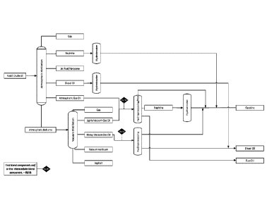
FIG 5 shows a simplified conventional refinery process where the petroleum
crude oil is first fractionated into Naphtha, Jet fuel/kerosene, Diesel oil,
atmospheric gas oil and atmospheric bottoms by atmospheric distillation. Each
of those fractions are submitted to further hydroprocessing stages as needed
to ensure fuel spec compliance. It is desirable to utilize existing
infrastructure
to co-process the first fuel blend component containing renewable
hydrocarbon with the second blend component comprising a refinery stream
i.e. co-processing at existing refineries for pretroleum oil.
Several potential drop in points at the refinery exist. In all cases,
compatibility
of the first blend component is critical to ensure smooth refinery operation
during co-processing, e.g. blend components should not separate during use,
storage and/or by dilution with other blends for use in the same application.
It
has been shown in the prior art that specific fractions (distillates) of
renewable
crude oils (hydrocarbon substance in the present context) can be co-
processed with certain petroleum fractions (second blend component) at least
in relatively small blending ratios with acceptable catalyst deactivation
rates
e.g. Ying (2019). However, the prior art co-processing methodologies typically
also generate significant amount of residues. The residues typically comprises
heavier oil components that are difficult to process further into desirable
higher
value products and therefore constitute a process loss that reduces the
overall
process efficiency. Such residues in prior art processes may be generated as
CA 03139861 2021-11-10
WO 2020/228991 PCT/EP2020/025223
27
a result of blending petroleum derived compositions with the renewable crude
oil and separating the noncompatible part (i.e. the residues) whereby the
first
blend component typically comprises a lighter fraction of the original first
blend
component or as a result of fractionation of the renewable crude oil into a
lighter distillate fraction and a heavier residue fraction.
For the hydrocarbon blends according to present invention the amount of
residues is minimized or eliminated i.e. the overall process efficiency is
improved. As a consequence the hydrocarbon blends according to the present
invention will typically have higher amount of higher boiling components that
can be processed into higher value products having a low carbon foot print
compared to conventional petroleum derived products due to the high amount
of renewables
A particularly attractive drop in point for the intermediate blend component
according to the invention or blending point resulting in a hydrocarbon blend
according to the the present invention is blending with gas oil and/or vacuum
gas oil prior to hydroprocessing as will further be illustrated by the
solubility
profiles exemplified in the following. As the compatibility of the hydrocarbon
blends according to the present invention is improved, further advantages,
such as enhanced processability e.g. less tendency to reactor clogging, less
catalyst deactivation, generally smoother and robust refinery operation and
higher ratios of the first fuel blend component, may be obtained by the
hydrocarbon blends according to the present invention. All of these are
important decision factors for a refinery to introduce unconventional first
blend
components containing renewable components into refineries.
Example 5: Hansen Solubility Parameters
Hansen Solubilty Parameters (HSP) is a methodology for describing the
solubility, blendability and stability of various solvents and substances and
is
widely used in e.g. the polymer and paint industries. A good description of
the
28
methodology is given in C.M. Hansen, "Hansen Solubility Parameters ¨ A
Users Handbook", Second Edition, CRC Press, Taylor & Francis Group, LLC.
(2007).
The methodology takes three types of molecular interactions into
consideration: AEd for dispersion (related to van der Waals forces); AE0 for
polarity (related to dipole Moment) and, AEI, for hydrogen bonding, (Eq.1).
The
total solubility parameter (Or), is obtained by dividing equation 1 by the
molar
volume yields (Eq.2).
AE = AEd + AEp + AE,, (Eq.1)
0 = gi + (V, + og, (Eq.2)
As described by Hansen, these three parameters can be illustrated in a 3D
diagram as a fixed point for pure solvents and as a solubility sphere for
complex mixtures samples. The center of a solubility sphere corresponds to its
Hansen Solubility parameters and its radius (R0), or so-called interaction
radius, determines the boundary of suitable solvents, which are normally
contained within the sphere, with the insoluble solvents located on the
outside
of the sphere. Hansen Solubility Parameters is based on "like dissolves like"
principle in which the Hansen Solubility Parameter distance metric measures
likeness, which means solvents with similar values of OD, Op, and OH
parameters are likely to be compatible.
When a solubility profile is determined on complex mixtures, there are two
parameters that should be included in the study, the distance between
materials (Ra) in the sphere plots and the relative distance of one solvent or
mixture of two or more solvents from the centre of the sphere (RED number).
Ra can be determined by volume or weight additivity of the respective
Date Recue/Date Received 2022-07-11
CA 03139861 2021-11-10
WO 2020/228991 PCT/EP2020/025223
29
parameters (Eq. 3), and the RED number corresponds to the ratio between Ra
and the sphere radius (Ro) (Eq.4)
Ra2 =4(8
dl 6d2)2 (8p1 (5p2)2 (8h1 42)2 (a1.3)
RED = (Eq.4)
The relative distance RED is equal to 0 when the solvent and the sample under
investigation have the same Hansen Solubility Parameters; compatible
solvents or mixture thereof will have RED values less than 1 and, the RED
value will increase gradually with the reduction of solubility in between
solvent
and solute.
Determination of Hansen Solubility Parameters
The Hansen Solubility Parameters for renewable crude oils Oil A, Oil B, Oil C
produced in example 1 and upgraded renewable oils from example 2 and 3as
well as different fossil crude oils and boiling point fractions were
determined
using the solvents and procedures described below.
Materials
For comparison purpose, solubility profiles of a fossil crude oil was
determined.
For the solubility tests, the following solvents acquired from commercial
chemical suppliers were used: 1-propanol (_>_99.5%), 1-butanol (99.8%), 2-
butanone (99.0%), 2-heptanone (98%), acetaldehyde (99%), acetyl
chloride (_.99.9%), acetone (_>_99.9%), acetonitrile (_>_99.9%), acetylacetone
(99%), 1-Butanethuil (99%) cyclohexane (99.5%), cyclopentanone
(.99%), diethyl ether (.99.0%), ethyl acetate (99.8%), furfural (.98 /0),
hexanal (97%), hexane (97.0%), isopropyl acetate (98%), lactic acid
solution (_.85%), m-cresol (99%), methanol (.99.9%), pentane (.99 /0),
phenol liquid (89.0%), tetrahydrofural (99.9%), toluene (99.8%) Sigma-
CA 03139861 2021-11-10
WO 2020/228991 PCT/EP2020/025223
Aldrich. Tetrahydrofurfuryl alcohol (99%), 1-methylimidazole (99%), 2,6
dimethylphenol (99%), dimethyl disulfide (99.0%), glycidyl methacrylate
(.?.:97.0 /0), trirolyl phosphate (90%) Aldrich. 2- methoxyphenol
anisole
(99%), dichloromethane (99.5%), propylene oxide (99%) Alfa Aesar.
5 Glycerol and ethylene glycol (general use) BDH. Hydrogen peroxide (USP-10
volume) Atoma.
Procedure for the estimation of the Hansen Solubility Parameters
The Hansen Solubility Parameters of the oils studied were determined by a set
10 of solubility tests and HSP model described in in C.M. Hansen, "Hansen
Solubility Parameters ¨ A Users Handbook", Second Edition, CRC Press,
Taylor & Francis Group, LLC. (2007), and HSPiP software writen by Abbott S.
& Yamamoto H. (2008-15).
15 Initially, 20 organic solvents were mixed with the oils in question at
ambient
temperature and classified as "good" (i.e. soluble), "partially soluble" or
"bad"
(i.e. insoluble) solvents based on the observed and measured degree of
solubility.
20 As the solubility parameters of the oils studied were unknown, the set
of
solvents used for the first screening had a wide range of Hansen Solubility
Parameters. After the initial solubility tests were completed and a first
approximation of HSP achieved, solvents with Parameters closer to those of
the oil studied were selected in order to increase the precision of the Hansen
25 Solubility Parameter model. A pseudo-3-D representation (sphere) of the
Hansen Solubility Parameters was built from the initial results using the
HSPiP
software is shown in FIG 8.
In this representation, the "good" solvents are placed inside or on the
surface
30 of the sphere, while partially soluble or insoluble solvents are placed
outside
the sphere. Once the initial Hansen Solubility Parameters are determined for
CA 03139861 2021-11-10
WO 2020/228991 PCT/EP2020/025223
31
the oil studied, the software estimates the relative distance (RED) by
equation
5. RED is the ratio of the modified difference between the solubility
parameters
of two substances, Ra (i.e. samples under study and a solvent), and the
maximum solubility parameter difference, which still allows the sample to be
dissolved in the solvent, Rm.
F(5D2-5pi)2+(8P2-46P1)2 (81/2-48H1)21
RED = Ra2 = _______________________ 2 Eq. (5)
Rm- Rm
Thus, the relative distance RED is equal to zero (RED = 0) when the solvent
and the sample under investigation have the same Hansen Solubility
Parameters. Red is equal to 1 (RED = 1) when the HSPs of the solvent are
placed on the surface of the sphere, and RED is greater than 1 (RED > 1)
when the sample is insoluble in the solvent, or the solvent is a poor solvent.
Once the approximate Hansen Solubility Parameters and RED values are
estimated for the oil in question, the precision of the model can be
increased.
This is achieved by performing solubility tests with a new set of solvents or
mixtures of solvents selected based on their RED values as predicted by the
HSPiP software. Hansen Solubility Parameters of both tested solvents and
mixtures should be placed on the surface and near to the center of the 3D
sphere model. After the model is refined, the software HSPiP can be used as
a prediction tool of suitable solvents depending on the function required;
i.e.
bridge of solubility, emulsion breaker, precipitation of insoluble material on
a
determined chemical. A list of solvents and solvent mixtures used is
presented in FIG 9a/9b,
The solubility tests were performed in a set of conical glass tubes with cap,
by
placing approximately 0.5 g of one sample and 5 ml of a solvent or mixture.
The solubility tests were performed in triplicate. The tubes were kept under
sonication for 5 hours and allowed to rest overnight at room temperature.
CA 03139861 2021-11-10
WO 2020/228991 PCT/EP2020/025223
32
Subsequently, the contents of each tube were visually inspected and classified
in 5 categories as: soluble(1): when there is no observable phase separation
or solid precipitation in the glass tubes; partially soluble (2-4) when big
solids
or a lump of oil appears, indicating that the sample is not completely
dissolved
in the solvent or the mixture; and, not soluble (0) are those mixtures that
have
well-defined phases. The degree of partial solubility ranges from 2 to 4, with
2
indicating the highest relative solubility FIG. 6 illustrates examples of each
of
the solubility categories.
Due to the dark color of the samples, it is difficult to visually distinguish
between the categories soluble (1) and partially soluble (2) so these samples
were marked "uncertain". To assess the solubility of these "uncertain"
samples,
the "spot test" method was used as a more precise blend
stability/compatibility
indicator. This method is widely used to assess the compatibility of marine
fuel
blends and has been used e.g by Redelius [P. Redelius, "Bitumen solubility
model using hansen solubility parameter," Energy and Fuels, vol. 18, no. 4,
pp. 1087-1092, 2004] for Hansen Solubility Parameter analysis. The spot test
was performed by placing a drop of each "uncertain" solution on a filter
paper,
and evaluated based on the criteria of the spot test method given in P.
Products, and R. S. Sheet, "Cleanliness and Compatibility of Residual Fuels
by Spot Test," vol. 4, no. Reapproved 2014, pp. 2014-2016, 2016: If a uniform
color spot is formed as shown in FIG. 7 a the mixture is considered fully
soluble
(i.e. category 1), whereas if two separate concentric spots are formed as
shown in FIG. 7b, the solvent is considered partially soluble (i.e. category
2).
Example 6: Hansen Solubility Parameters for renewable crude oils.
The Hansen Solubility Parameters and solubility profiles of the renewable
crude oils produced by hydrothermal liquefaction in example 1 (Oil A, B and
C) were determined using a total of 36 solvents and 23 solvent mixtures. The
results are summarized in FIG.8a/8b. The 3D representation of the HSPs for
Oil A (Fig. 8) has a good fit of 0.965 with 24 solvents placed inside the
sphere
CA 03139861 2021-11-10
WO 2020/228991 PCT/EP2020/025223
33
and 33 solvents outside the sphere. The score and RED values for each
solvent are shown in FIG. 8a/8b. The solvents with a RED value equal to 1 are
located on the surface of the sphere, those with values less than 1 are
located
inside of the sphere and those with values greater than 1 are located outside
of the sphere. Thus, the closer the RED value is to 0, the closer the solvent
or
mixture is to the center of the sphere. To estimate the correlation between
Hansen Solubility Parameters for the renewable crude Crude Oils, the
parameters for Oil B and Oil C were also determined. In this case 11 solvents
were enough for the HSP determination as shown in FIG. 9a/9b.
The three renewable crude oils, Oil A (6D: 19.19, Op: 14.52, OH: 11.61,
Ro:9.3),
Oil B (OD: 18.36, Op: 10.43, 6H: 10.06, Ro: 6.7), and Oil C (OD: 18.13, Op:
9.59,
OH: 9.25, Ro: 6.8) have similar solubility profiles and can be visualized in
Fig.
11. However, Oil A has higher polarity and stronger hydrogen bonding
interactions than oils B and C. Comparing the parameters for the three
biocrudes, it can be seen that they are similar with the only exception being
that Oil C was partially soluble in 1-Methyl imidazole while oils A and B were
soluble as seen in Fig. 9a. The difference in the Hansen Solubility Parametrs
for the renewable crude oils under study can be associated with the biomass
feedstock used to produced each oil, i.e. Birch in Oil A; Pine EW in Oil B and
Oil C , and processing conditions as described in example 1.
Example 7: Hansen Solubility Parameters for partially upgraded and
upgraded oil
The Hansen Solubility Parameters Score and RED values obtained for partially
upgraded renewable oils in the example 2 are summarized in Fig. 8a/8b and
Fig 9.
As shown in Fig 9a/9b a total of 18 solvents were used to determine the
Hansen Solubility Parameters of the partially upgraded renewable oil II from
example 2 (OD: 17.95, Op: 10.96, 6H: 9.96). A 3D representation of the Hansen
CA 03139861 2021-11-10
WO 2020/228991 PCT/EP2020/025223
34
Solubility sphere for the partially upgraded from example 2 is shown in FIG.
11. The Hansen Solubility Sphere has a fit of 0.883, excluding 1 outlier
solvent.
15 solvents were used to determine the Hansen solubility profile of the
upgraded renewable oil following the methodology described in example 3.
The Hansen Solubility Sphere of the upgraded oil is visualized in Fig 11 and
has a fit of 1.000 and the Hansen Solubility Parameters: 6D: 17.36, op: 8.01,
6H: 7.59.
As seen from figure 12, the Hansen Solubility Parameters and radius of
solubility were different for biocrude, partial upgraded and upgraded oil
which
indicates the effect of upgrading process on solubility properties. The
renewable crude oil (Oil A) has a strong polarity, high disperse interaction
and
a strong hydrogen bonding interaction. After one step of upgrading (partial
upgrading) including hydrogenation, full deoxygenation and mild cracking of
the renewable crude oil, the so-called partial upgraded oil exhibited
considerable reduction in polarity, hydrogen bonding interaction and radius of
solubility. This can be attributed to the fact that the presence of oxygen,
heteroatonns and metals highly contributed to the polarity parameter. In fact
the more upgraded the crude oil, the lower the values of the three Hansen
.. Solubility Parameters and this can be clearly visualized when comparing the
solubility profile of the renewable crude oil and partially upgraded oil with
a
fully upgraded oil. The latter exhibited lower dispersion, polarity and
hydrogen
bonding interaction as well as lower radius of solubility.
The RED value of the partially upgraded oil in the solubility sphere of the
biocrude oil, is rather low (0.524) suggesting full solubility. However, the
RED
value of the upgraded oil (RED = 0.934) is close to the solubility limit of
RED
> 1 showing poor solubility in the biocrude. Therefore the solubility between
biocrude and upgraded oil is inversely proportional to the degree of upgrading
thereof.
CA 03139861 2021-11-10
WO 2020/228991 PCT/EP2020/025223
Example 8: Compatibility of upgraded renewable oil with petroleum
crude oils
Compatability of the renewable oil with petroleum oils are important for many
practical applications of the renewable oil e.g. for co-processing in
petroleum
5 refeneries and for transport in pipelines.
A Hansen Solubility Parameter analysis was used to test compatibility of
upgraded renewable oil with Vacuum Gas Oil ¨ VG0, bitumen and petroleum
crude such purposes. The results are shown in Fig. 14 and visualized in Fig.
10 13a, 13b and 13c. As seen from the figures, the petroleum crude oil, VG0
and
bitumen has differences in polarity and hydrogen bonding parameters
compared to the upgraded renewable oil. However, the solubility profiles also
show that there are areas of overlapping in between their Hansen Solubility
Parameter spheres. Furthermore, the center of the sphere of the petroleum
15 crude oil is placed in the boundary limit of solubility of upgraded oil
i.e. RED =
0.981, which not only increases the solubility ratio between the upgraded
biocrude and the petroleum crude oil, but also indicates that after a deep
hydrotreatment, the upgraded biocrude solubility profile becomes very close to
the solubility profile of the petroleum crude oil, which means that after
20 upgrading the renewable crude oil via hydroprocessing, the upgraded oil
present simillar properties compare to the fossil crude oil.
Example 9: Co-processing biocrude and/or partially upgraded renewable
oil with petroleum crude oils
25 To assess co-processing of renewable crude oil and/or partially upgraded
renewable oil with petroleum crude oil and heavy petroleum crude oil fractions
such as Vacuum Gas Oil (VGO) the solubility profiles of a petroleum crude oils
were determined. A total of 21 solvents were used to determine the Hansen
Solubility Parameters of the fossil crude oil (öD: 18.47, op: 6.67, 6H: 3.58)
and
30 VG0 (6D: 19.1-19.4, 6P: 3.4-4.2, 6H: 4.2-4.4). Its 3D representation has
a great
fit of 1.000 with a radius of solubility of 5.6 and 5.8, respectively FIG. 13
a, b
CA 03139861 2021-11-10
WO 2020/228991 PCT/EP2020/025223
36
and c show the spheres of solubility profiles obtained for renewable crude
oil,
partial upgraded, fossil crude oil, VG() and Bitumen (6D: 18.4, op: 4.0, 6H:
0.6;
Ro: 5.76). Bitumen Hansen solubility parameter were determined by Redelius,
"Bitumen Solubility Model using Hansen Solubility Parameters, Energy and
Fuels, vol. 18, no .4, pp. 1087-1092, 2005.
Even though the disperse interaction parameters of the biocrude, fossil crude
oil, VG() and bitumen are similar, there is a considerable difference in the
polarity and hydrogen bonding interaction parameters. The RED values of
fossil oil, VG0 and Bitumen in the solubility sphere of biocrude are 1.248,
.. 1.415 and 1.506, respectively. These RED values are above the limit of
solubility RED 1 showing only partial solubility in the biocrude (FIG
12a).
This was confirmed by blending laboratory tests in proportions from 5 to 50
wt.% of biocrude in petroleum crude oil. The same behavior was observed
when comparing the Hansen Solubility Parameters of partially upgraded oil
with petroleum crude oil, VG0 and bitumen, where the difference in the
polarity
and hydrogen bonding interaction parameters is high. The RED values of fossil
oil, VG() and Bitumen in the solubility sphere of partially upgraded oil are
above the limit of solubility RED ?: 1 (1.282, 1.534 and 1.611, respectively),
showing partial solubility in the partially upgraded oil at room temperature.
The
solubility of mixtures of partial upgraded biocrude and petroleum crude oil,
bitumen or vacuum residue is improved by increasing the temperature. The
experimental tests show that mixtures of partial upgraded biocrude and
petroleum oil or heavy derivated fraction in the ratio of 9:1 become soluble
and
compatible by spot test analysis when the mixtures are heated to a
temperature in the range 70-130 C. Hence, the first blend component
comprising a renewable hydrocarbon and the linker substance, and the second
component is in an advantageous embodiment of the present invention both
heated to a temperature of 70-150 C such as 80 to 120 C prior to manipulating
them to form a homogeneous mixture. For a selection of linker substances
that fulfill all the above solubility and usability criteria, various linker
substances
such as solvent combinations were screened on the HSPiP software to identify
CA 03139861 2021-11-10
WO 2020/228991 PCT/EP2020/025223
37
suitable mixtures that do not exceed the solubility limit Le. RED < 1. Through
the testing of a number of solvents and mixtures; it was blending tests
confirmed that the addition of 2 wt.% of Toluene or the blend MEK/m-cresol
(70:30) increase the solubility of biocrude and Bitumen. Although the mixture
were not fully compatible at room temperature, it becomes compatible by spot
test analysis when the blend is heated to 150 C.
Example 10: Hansen Solubility Parameters of fractions of renewable
crude oil and upgraded renewable oil
Compatibility of fractions of raw biocrude, partially upgraded oil and
upgraded
oil with its fossil counterparts is important to evaluate those blends in
process
such as recirculation in renewable oil hydroprocessing and co-processing with
petroleum fractions and/or other bio-oils. Therefore, the Hansen Solubility
Parameters of the fractions listed below were determined by methodology
described in example 4. The upgraded fractions were obtained by distillation
of the partially upgraded and upgraded oils were produced as described in
examples 2 and 3. Figures 15a and 15b shown the 3D representation of the
Hansen solubility profile of the upgraded heavy fractions.
Table 8: Hansen Solubility Parameters fractions of raw biocrude, partially
upgraded oil and upgraded oil
op OH
Sample Ro
[M PAv2] [M PAv2] [MPA1I2]
Renewable
crude oil
18-19.5 8-13 7-10 5-9
fraction IBP-
530 C
Heavy
fraction - 17-19 7.5-12 7-10 5-9
PUO
CA 03139861 2021-11-10
WO 2020/228991 PCT/EP2020/025223
38
Heavy
Fraction - 17-19 7-9.5 7-10.5 4-8
UO
PUO: Partially Upgraded Oil
UO: Upgraded Oil
As seen from figure 15a and 15b, the Hansen Solubility Parameters and radius
of solubility becames simillar to fossil fuels i.e. Ultra Low Sulphur Fuel Oil
¨
ULSFO and High Sulphur Fuel Oil - HSFO.
Example 11: Compatible diluents, viscosity reducing agents and storage
stability enhancers for renewable crude oils
Fully compatible synthetic diluents or viscosity and/or density reducing
agents
for the renewable crude oil are desirable for many practical applications
including diluents to improve fluidity of the renewable crude oil, enhance
separation efficiency during the production process e.g. by solvent/diluent
assisted separation of the renewable crude oil or to improve the storage
stability of the crude oils.
Using the solubility profile of the biocrude, a list of solvents were selected
that
fit within the sphere of "Oil A" Hansen Solubility Parameters solubility
profile.
These solvents were selected as suitable to compose the desired "synthetic
lights" mixture.
This list of solvents was further narrowed using the following criteria: a)
low-
toxicity, b) ease of separation from the renewable crude oil e.g. by boiling
point,
c) non-complex geometry, d) solvents that do not contribute increasing the
oxygen content of the biocrude, e) solvents that do not contain other
heteroatoms (i.e. Nitrogen, sulfur, chloride, etc.) or metals that can
contribute
to the deterioration of the quality of the biocrude f) local availability of
solvents
and g) cost.
CA 03139861 2021-11-10
WO 2020/228991
PCT/EP2020/025223
39
A light fraction with a cut off boiling point of 130 C was from renewable
crude
oil A produced in example 1 produced in a rotary evaporator. The families of
compounds that represent the major volume percentages of the renewable
crude light fraction were established based on the gas chromatography
analysis of the renewable crude oil light, i.e. Substituted benzenes: 15
vol.%,
C4-C6 ketones: 50 vol.%, alkanes: 24 vol.% and alcohols: 11 vol.%.
Based on this approach, a mixture containing methyl ethyl ketone, alkanes
(e.g. octane, nonane), p-xylene and/or toluene, and 1-butanol and/or propanol
was identified as suitable to emulate the light ends of the renewable crude
oil
as "synthetic lights".
Table 9. HydrofactionTM crude oil lights end identification and mixtures
examples
Family
Composition Proposed Mixture composition [vol.%]
[v o I .1)/0] solvents 1 2 3
Substituted 15 10 10
p-xylenea
benzene
C4-C6 ketones 50 MEK 50 40 25
AI kanes 24 Octane 24 30 35
Alcohols 11 1-butanol 11 20 30
RED -Biocrude 1.43 1.43 1.45
1.47
a p-xylene may be substituted by toluene, or by a solvent mixture of
toluene/xylene 50%/50%
Table 10. HSParameters of pure solvents and mixture examples
_______________________________ 8H ____ 6p __________ 8H
Solvent
[MPa1t2] [MPaia] [MPa1t2]
p-xylene 17.8 1 3.1
MEK 16 9 5.1
Octane 15.5 0 0
1-butanol 16 5.7 15.8
Mixture composition 1 16.3 5.3 4.8
Mixture composition 2 1 6.0 4.6 5.5
Mixture composition 3 16.0 4.1 6.3
The volume percentages of each solvent in the selected mixture are shown in
table 9. The initial value of RED score (1.53) of Hansen Solubiilty Parameters
CA 03139861 2021-11-10
WO 2020/228991 PCT/EP2020/025223
of a similar mixture (table 9) was obtained using the volume concentration of
the lights obtained by GC-MS.
Table 9 further show some volume concentrations of the solvent mixture that
5 have similar RED values, which means that all the mixtures proposed are
close
enough to the behaviour of the real light mixture from the renewable crude oil
and the Hansen Solubility Parameters for the individual solvent and the
combined linker substance I shown in table 10.
10 Example 12: Co-processing biocrude and/or partially upgraded
renewable crude oil with fossil crude oils using linker substances
For a selection of solvents that fulfill all the above solubility and
usability
criteria, various linker substances such as solvent combinations were
screened on the HSPiP software to identify suitable mixtures that do not
15 exceed the solubility limit i.e. RED < 1.
Through the testing of a number of solvents and mixtures; it was confirmed
that 1) the addition of 2 wt.% of Toluene or 2 wt % of the blend MEK/m-cresol
(70:30) increase the solubility of biocrude and Bitumen. Although the mixture
20 were not fully compatible at room temperature, it becomes compatible by
spot
test analysis when the blend is heated to 150 C. 2) Biocrude and Vacum Gas
Oil (VGO) blend become compatible by the addition 2 wt.% of solvent mixtures
with HSP of about op: 15.6, op: 8.3, ow 9.4. e.g Acetone (60 wt. /0)+ Propanol
(30 wt.%)+ pentane (10 wt.%). 3) Partially upgraded oil and VG0 blends are
25 compatible in a proportion up to 25% of Partially upgraded oil without
the use
of linkers.
Example 13: Linker substances for blending of renewable oil with marine
fuels to produce low sulphur marine blends
30 Blending tests were performed in order to test the solubility of low
sulphur
marine fuel blendstocks with renewable liquids (crude oil, partially upgraded
CA 03139861 2021-11-10
WO 2020/228991 PCT/EP2020/025223
41
renewable oils and the 350-F C boiling fractions from the same oils) using
concentrations in the range of 2 to 50 wt.% of renewable liquids. The tests
showed only partial solubility of the renewable liquids with low sulfur marine
fuel blendstock (RMG 180 Ultra Low sulphur fuel oil according to the IS08217
(2012) standard), at any of the blending ratios tested. Obviously, such blend
stock has compatibility issues that lead to precipitation, separation, and/or
sedimentation of the insoluble components, etc. if used directly in blends
with
other marine fuels. Hence, a renewable blendstock not suffering from such
compatibility issues are highly desirable.
A Hansen Solubility profile analysis was performed in order to identify a
linker
substance that will enable the blending of liquids in marine fuels. As
visualized
in Fig. 15a and 15b, there is overlapping of the sphere of solubility for each
oil,
which means that although their Hansen Solubility Parameters are different
and the RED distance between their centre of solubility is greater than 1,
they
are partially soluble.
The identified potential mixtures of solvents that may acts as linker
substances
are mainly composed of sulfur-containing solvents, ketones, alkanes, and
alcohols as well as aromatic compounds like toluene, xylene, and creosol.
Example 14: Low sulphur fuel blend comprising a first fuel blend
component containing a renewable component
Based on the solubility profiles described in example 13 first fuel blend
components containing a renewable component were produced from the
heavy fraction of upgraded renewable crude oil having a boiling point of
350-F C and the Hansen Solubility Parameters (op: 17-18.5, op: 7-9.5, oH: 7-
10.5; Ro: 4-8), and a linker substance comprising RMG380 high sulphur fuel
oil (HSFO) with the Hansen Solubility Parameters (OD: 18-19.7, Op: 3-6, ow 3-
6; Ro: 4-6) and a sulphur content of 2.49% by weight in concentrations from 0
to 10 wt. /0.
CA 03139861 2021-11-10
WO 2020/228991 PCT/EP2020/025223
42
The first fuel blend components with the different linker substance
concentrations up to 10% by weight were mixed with a second fuel component
comprising ultra low sulphur fuel oil (ULSFO) according to the ISO 8217 RMG
180 ultra low sulphur specification having Hansen Solubility Parameters (6D:
18-19.7, 6p: 3-6, 6H: 3-4.5; Ro: 4-6.5).
As expected, the first fuel blend component without the linker substance was
found to be incompatible when mixed the upgraded heavy fraction with two
marine fuels (i.e.ultra low sulphur and high sulphur marine fuels) in
proportions
of 5 to 50 wt.% of upgraded renewable fraction. However, for first fuel blend
components comprising 2% by weight or higher of the high sulphur linker
substance the blends were found to be compatible. It was further found that
the low sulphur fuel blend remained compatible at all ratios by dilution with
the
ultra low sulphur fuel oil (ULSFO) e.g. ultra low sulphur fuel oil can be
added
to the same tank as the low sulphur fuel blend according to the present
invention without any compatibility issues.
An example of the properties of a low sulphur fuel blend according to the
present invention is shown in Fig. 16 for a blend of 62 vol. /0 first fuel
component containing a renewable component (Steeper HF, 350 C boiling
point fraction).
Example 15: Low sulphur blend of a first fuel blend component
comprising the heavy fraction of partially upgraded oil (3 wt.% Oxygen)
and Marine Gas Oil
Blending tests were performed using of a first fuel blend component
comprising the heavy fraction (Boiling point 350+ C) from example 10 with an
oxygen content of 3 wt.% and a second fuel blend component comprising
marine gas oil (MGO) according to the ISO 8217 DMA standard. The heavy
CA 03139861 2021-11-10
WO 2020/228991 PCT/EP2020/025223
43
fraction had the Hansen Solubility Parameters (OD: 17-19, op: 7.5-12, OH: 7-
10; Ro: 5-9) and Marine Gas Oil (MGO) had the Hansen Solubility Parameters
(OD: 18-19.7, Op: 3-6, OH: 3-5; Ro: 4.5-6.5). As the RED centers of
solubilities
are higher than 1 why the blends is expected to be only partially soluble
without
a linker substance according to the present invention. As seen from spot tests
and microscope tests in Fig. 17 this was also observed in the blending test
for
ratios of 50 wt% Heavy Fraction from partially upgraded renewable oil
(HFPUO)/50 wt % Marine Gas Oil (MGO)and 25 wt % HFPUO/75 wt % MGO.
Example 16: Low sulphur blend of a first fuel blend component
comprising the heavy fraction of partially upgraded oil (3 wt.% 0) and
high sulphur fuel oil (HSFO)
Blending tests were performed using of a first fuel blend component
comprising the heavy fraction (Boiling point 350-F- C) from example 10 with an
oxygen content of 3 wt.% and a second fuel blend component comprising
marine gas oil (Ultra Low Sulphur Fuel Oil) according to the ISO 8217 DMA
standard. The heavy fraction had the Hansen Solubility Parameters (OD: 17-
19, Op: 7.5-12, OH: 7-10; Ro: 5-9) and High Sulphur Fuel Oil had the Hansen
Solubility Parameters (OD: 18-19.7, Op: 3-6, OH: 3-6; Ro: 3-6). As the RED
.. centers of solubilities are close to 1, the blends were expected to be
soluble
or compatible without a linker substance according to the present invention.
As seen from spot tests and microscope tests in Fig. 18 this was also
observed in the blending test for ratios of 50 wt.% Heavy Fraction of
Partially
Upgraded Oil (HFPUO)/50 wt% High Sulphur Fuel Oil (HSFO) and 25 wt.%
HFPUO/75 wt.% HSFO meaning that the HSFO is a suitable linker substance
to achieved the main objective of this invention, obtained a low sulphur fuel
blend of a first fuel blend component containing a renewable hydrocarbon
component as described in example 15.