Note: Descriptions are shown in the official language in which they were submitted.
CA 03108086 2021-01-29
WO 2020/069558 PCT/AU2019/051014
"Processing of Lithium Containing Brines"
Field of the Invention
[0001] The present invention relates to a method for the processing of
lithium
containing brines.
[0002] More particularly, the method of the present invention is intended
for use
in the production of a lithium bearing solution suitable for further
processing by
electrolysis. In turn, it is particularly intended that the processing by
electrolysis of
the lithium bearing solution provides a lithium hydroxide monohydrate product.
[0003] The present invention further relates to the production of a lithium
hydroxide monohydrate and/or lithium carbonate that is/are of battery grade.
Background Art
[0004] The current process employed by brine producers requires first the
conversion of lithium containing brine to lithium carbonate, requiring
treatment with
sodium carbonate (soda ash) to precipitate the lithium carbonate. This lithium
carbonate is then causticised using hydrated lime. This process is known to be
expensive and it employs complicated process unit operations. The lithium
carbonate produced in this manner by brine producers, using the soda ash
reaction
on a lithium chloride solution, produces technical grade lithium carbonate.
The
technical grade lithium carbonate in turn needs to be further purified using
an
expensive bicarbonation circuit.
[0005] Lithium containing brines obtained from solar brine ponds typically
contain
a number of impurities, present at what are considered by operators as high
levels.
As such, these lithium containing brines are not considered suitable for
electrolysis.
[0006] The method and product of the present invention have as one object
thereof to overcome substantially one or more of the above mentioned problems
associated with the methods and products of the prior art, or to at least
provide
useful alternatives thereto.
1
CA 03108086 2021-01-29
WO 2020/069558 PCT/AU2019/051014
[0007] The preceding discussion of the background art is intended to
facilitate an
understanding of the present invention only. This discussion is not an
acknowledgement or admission that any of the material referred to is or was
part of
the common general knowledge as at the priority date of the application.
[0008] Throughout the specification and claims, unless the context requires
otherwise, the word "comprise" or variations such as "comprises" or
"comprising", will
be understood to imply the inclusion of a stated integer or group of integers
but not
the exclusion of any other integer or group of integers.
[0009] Throughout the specification and claims, unless the context requires
otherwise, the term "battery grade lithium carbonate" refers to a product
having a
purity of about 99.5% or higher. Similarly, the term "battery grade lithium
hydroxide"
refers to a product having a purity of about 99% or higher.
[0010] The term brine, or brines, or variations thereof, is to be
understood to
include a solution of alkali and/or alkaline earth metal salt(s) in water, of
a natural or
possibly industrial source. The concentrations of the various salts can vary
widely.
The ions present in brines may include a combination of one or more of a
monovalent cation, such as lithium, multivalent cations, monovalent anions,
and
multivalent anions.
Disclosure of the Invention
[0011] In accordance with the present invention there is provided a method
for the
processing of lithium containing brines, the method comprising the method
steps of:
(i) Passing a lithium containing brine to a filtration step to remove
sulphates;
(ii) Passing a product of step (i) to a first ion exchange step to remove
divalent
impurities;
(iii) Passing a product of step (ii) to a second ion exchange step to remove
boron impurities;
2
CA 03108086 2021-01-29
WO 2020/069558 PCT/AU2019/051014
(iv) Passing a product of step (iii) to an electrolysis step to produce
lithium
hydroxide; and
(v) Passing a product of step (iv) to a crystallisation step that in turn
provides a
lithium hydroxide monohydrate product.
[0012] In one form, the present invention further comprises passing a spent
liquor
from the crystallisation step (v) to a carbonation step (vi) in which the
spent liquor is
reacted with carbon dioxide forming lithium bicarbonate. The thus formed
lithium
bicarbonate is preferably then heated in a heating step (vii) to precipitate
lithium
carbonate.
[0013] In a further form, the present invention further comprises the
washing,
drying and micronising of the precipitated lithium carbonate.
[0014] Preferably, the filtration step (i) utilises nano-filtration. Still
preferably, the
filtration step removes sulphates from the lithium brine to a level of less
than 1 gpl.
[0015] Preferably, the ion exchange step (ii) removes divalent impurities
selected
from the group of calcium, magnesium, strontium, and barium. Still preferably,
the
ion exchange step (ii) removes the divalent impurities from the lithium brine
to a level
of less than 0.1 ppm.
[0016] Preferably, the ion exchange step (iii) removes boron impurities
from the
lithium brine. Still preferably, the ion exchange step (iii) removes boron
impurities
from the lithium brine to a level of less than 0.1 ppm.
[0017] Preferably, the crystallisation step (v) utilises high vacuum low
temperature multiple effect crystallisation techniques and apparatus.
Brief Description of the Drawings
[0018] The present invention will now be described, by way of example only,
with
reference to the accompanying drawings, in which:-
3
CA 03108086 2021-01-29
WO 2020/069558 PCT/AU2019/051014
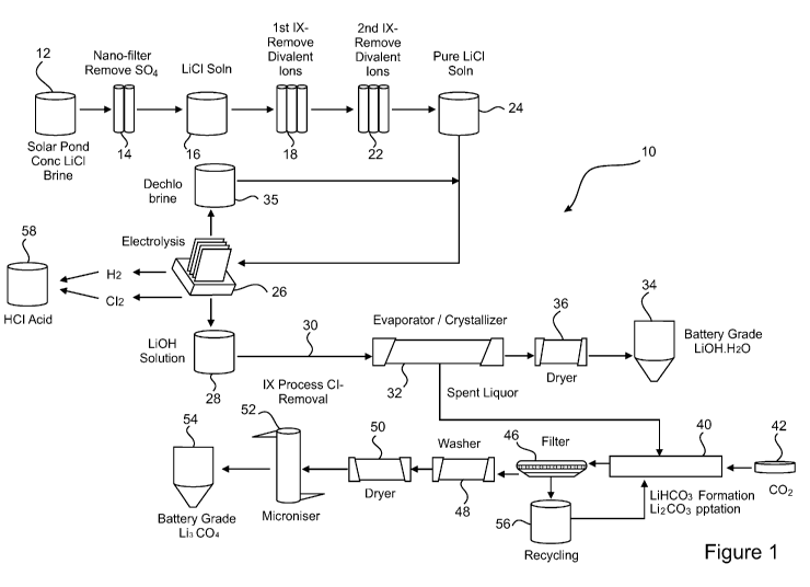
Figure 1 is a flow-sheet of a method for the processing of lithium containing
brines, the method being in accordance with one embodiment of the
present invention;
Figure 2 is a series of breakthrough curves for alkaline earth metals
present in the lithium brine passed to the first ion exchange step of the
method of Figure 1;
Figure 3 is an expanded view of the breakthrough curves of Figure 2;
Figure 4 is a series of breakthrough curves for boron removal in a second
ion exchange step;
Figure 5 is a schematic of the electrolyser constructed for the tests of
electrolysis;
Figure 6 shows the 5 cell stack used in the investigations of electrolysis,
with particular reference to the electrical connections to the DC power
supply;
Figure 7 shows the expansion characteristics of several ion-exchange
membranes, measured in 2% NaOH and 2% LiOH solutions;
Figure 8 shows the primary electrode reactions and the transport of
hydroxyl ions leading to current inefficiency in membrane cells during
electrolysis;
Figure 9 is a table of the specification of the lithium hydroxide monohydrate
product that can be obtained using the method of the present invention;
and
Figure 10 is a table of the specification of the lithium carbonate product
that
can be obtained using the method of the present invention.
4
CA 03108086 2021-01-29
WO 2020/069558 PCT/AU2019/051014
Best Mode(s) for Carrying Out the Invention
[0019] The present invention provides a method for the processing of
lithium
containing brines, the method comprising the method steps of:
(i) Passing a lithium containing brine to a filtration step to remove
sulphates;
(ii) Passing a product of step (i) to a first ion exchange step to remove
divalent
impurities;
(iii) Passing a product of step (ii) to a second ion exchange step to remove
boron impurities;
(iv) Passing a product of step (iii) to an electrolysis step to produce
lithium
hydroxide; and
(v) Passing a product of step (iv) to a crystallisation step that in turn
provides a
lithium hydroxide monohydrate product.
[0020] The method of the present invention, in one embodiment thereof, further
comprises passing a spent liquor from the crystallisation step (v) to a
carbonation
step (vi) in which the spent liquor is reacted with carbon dioxide forming
lithium
bicarbonate. The thus formed lithium bicarbonate is then heated in a heating
step
(vii) to precipitate lithium carbonate. The precipitated lithium carbonate is
then
washed, dried and micronised.
[0021] The filtration step (i) utilises nano-filtration and removes
sulphates from the
lithium brine to a level of less than 1 gpl. The ion exchange step (ii)
removes
divalent impurities selected from the group of calcium, magnesium, strontium,
and
barium to a level of less than 0.1 ppm.
[0022] The ion exchange step (iii) removes boron impurities from the
lithium brine
to a level of less than 0.1 ppm.
[0023] The crystallisation step (v) utilises high vacuum low temperature
multiple
effect crystallisation techniques and apparatus. Evaporators are classified by
the
CA 03108086 2021-01-29
WO 2020/069558 PCT/AU2019/051014
number of effects. For example, a single-effect evaporator uses steam to
provide
energy for vaporisation. The vapour product is condensed and removed from the
system. Similarly, in a double-effect evaporator, the vapour product off the
first
effect is used to provide energy for a second vaporisation unit. In turn, the
cascading of effects can continue over many stages. Multiple-effect
evaporators can
remove much larger amounts of solvent than is possible in a single effect. In
a
multiple effect arrangement, the latent heat of the vapour product from one
effect is
used to heat the following effect.
[0024] In Figure 1 there is shown a flow-sheet representing a method 10 for
the
processing of lithium containing brines, the method 10 being in accordance
with one
embodiment of the present invention.
[0025] The method 10 comprises the method steps of:
(i) Passing a lithium containing brine 12 to a filtration step 14 in which
sulphates are substantially removed;
(ii) Passing a product 16 of step (i) to a first ion exchange step 18 to
substantially remove divalent impurities;
(iii) Passing a product 20 of step (ii) to a second ion exchange step 22 to
substantially remove boron impurities;
(iv) Passing a product 24 of step (iii), comprising a substantially pure
lithium
chloride solution, to an electrolysis step 26 to produce a lithium hydroxide
solution 28; and
(v) Passing a product 30 of step (iv) to a crystallisation step 32, from which
a
battery grade lithium hydroxide monohydrate 34 is obtained, by way of a
drying step 36.
[0026] A dechlorinated brine 35 from the electrolysis step 26 may be recycled
to
the product 24 of step (iii) as further feed to the electrolysis step 26.
6
CA 03108086 2021-01-29
WO 2020/069558 PCT/AU2019/051014
[0027] The method 10 of the present invention, in one embodiment thereof,
further
comprises passing a spent liquor 38 from the crystallisation step (v) 32 to a
carbonation step (vi) 40, in which the spent liquor 38 is reacted with carbon
dioxide
42 forming lithium bicarbonate. The thus formed lithium bicarbonate is then
heated
in a heating step (vii) 44 to precipitate lithium carbonate. The precipitated
lithium
carbonate is filtered 46, then washed 48, dried 50 and micronised 52. These
steps
provide a battery grade lithium carbonate 54.
[0028] Liquid from the filtration 46 of the lithium carbonate precipitated
in the
heating step 44 is recycled 56 to the carbonation step 40.
[0029] The filtration step (i) 14 utilises nano-filtration and removes
sulphates from
the lithium brine 12 to a level of less than 1 gpl. The first ion exchange
step (ii) 18
removes divalent impurities selected from the group of calcium, magnesium,
strontium, and barium to a level of less than 0.1 ppm.
[0030] The ion exchange step (iii) 22 removes boron impurities from the
lithium
brine to a level of less than 0.1 ppm.
[0031] The electrolysis step 26 produces, in addition to the lithium
hydroxide
solution 28, both hydrogen and chlorine gas. The hydrogen and chlorine gases
are
catalytically combined to produce hydrochloric acid 58.
[0032] The crystallisation step (v) 32 utilises high vacuum low temperature
multiple effect crystallisation techniques and apparatus.
[0033] The method of the present invention may be further understood with
reference to the following non-limiting example.
EXAMPLE 1
[0034] A typical solar dried brine composition is provided in Table 1 below
together with some typical physical characteristics thereof.
7
CA 03108086 2021-01-29
WO 2020/069558 PCT/AU2019/051014
Table 1 ¨ Brine Composition and Characteristics
Item %
Lithium Chloride 30.0
Sodium Borate 0.05
Calcium Chloride 0.01
Potassium Chloride 0.80
Sodium Chloride 3.50
Magnesium Chloride 0.04
Sodium Sulphate 0.34
Water 65.26
SG 1.17
pH 8.90
[0035] Sulphates in the typical brine from a solar dried pond operation,
predominantly present as sodium sulphate, are recorded at 0.34% (3.40 g/L).
The
Applicant has determined that the maximum allowable sulphate present as sodium
sulphate for electrolysis should not exceed 1 g/L. The Applicant has
determined that
nano-flitration is the preferred mechanism to remove sulphate ions. Two
membranes, both from Dow, Dow N9OTM membrane and Dow XUS290504TM were
found to be very successful in removing sulphate ions to an acceptable level.
The
results are provided below. The best performance was observed by Dow
XUS29OSO4TM membrane. Dow XUS29OSO4TM membrane performed better in
rejection rate, however at a lower reflux rate.
[0036] A simulated brine was filtered through 0.4 pm glass fibre filter
prior to
analysis to remove fines and particulate matter (NTU un-filtered brine ¨ 6.42;
filtered
¨ 0.20 NTU). The nano filtration (NF) membranes were wetted in ultrapure water
for
24 hours prior to use. A dead end filtration cell from Sterlitech HP47SOTM was
rinsed
with ultrapure water and assembled with the wetted membrane in the correct
orientation. The filtration system was assembled on a magnetic stirrer plate
(set to
300 rpm) and connected to a size G nitrogen gas cylinder. The mass of the
filtrate
was recorded every second and converted to a flux rate (L.min-1.m-2) by
incorporating the membrane surface area and solution density.
8
CA 03108086 2021-01-29
WO 2020/069558 PCT/AU2019/051014
[0037] Ultrapure water was passed through the membrane until a stable flux was
observed. Simulated brine (150 mL) was added to the cell reservoir and
filtered until
a minimum of 10 mL of filtrate was collected. The filtrate collected was
sampled for
ICP-OES analysis (1 mL aliquot), acidified with 200 pL of HCI and 200 pL HNO3
and
diluted to 10 mL volume with 2% HNO3.
[0038] The Dow membranes were prepared by cutting a 150 mm cross-section of
the membrane module. Each membrane was unwound where a 300 mm strip of flat
sheet membrane was obtained. Five 47 mm discs were cut and placed immediately
in ultrapure water. The remaining membrane section, as well as the unused
membrane module, were wetted with sodium metabisulfite (50 ppm as S02) and
stored at 4 C for future use.
[0039] Brine samples were analysed using a Perkin Elmer 8300DVTM ICP-OES
fitted with an ESI SC-4DXTM autosampler and PrepFAST 2TM sample handling unit
for online internal standardisation and auto-dilution of samples and
calibration
standards. Purified nitric acid was used for the preparation of all standards
and
blank solutions used throughout the analysis.
[0040] Instrument calibration was performed using multi-element standards
prepared in-house from Inductively Coupled Plasma Mass Spectrometer (ICP-MS)
grade single element stock solutions (High Purity Standards, Charleston, USA).
Method robustness, accuracy and precision was verified by continuing analysis
of a
number of Certified Reference Materials (CRM's) covering a range of common
matrices and analyte concentrations (N 1ST, Gaithersburg, MD, USA, United
States
Geological Survey, Reston, VA, USA).
[0041] All brine samples were analysed in 1:10 and 1:10,000 dilution to
report the
entire suite of elemental composition.
[0042] Table 2 below depicts that both Dow N9OTM as well as Dow XU5290504TM
membrane are suitable for removing sulphates to an acceptable level. Dow
XU5290504TM membrane performed better in rejection rate however at a lower
ref lux rate.
9
CA 03108086 2021-01-29
WO 2020/069558 PCT/AU2019/051014
Table 2- Sulphate Removal Results
DOW N90 (Flux 0.06 L/min/m2) 20 bar
Mg Ca S B
Filtrate (mg/L) 25.6 23.36 108.3 7.697 48490 7999 3126 0.4072
Rejection (Y()) 67.7 26.6 86.5 70.8 1.6 8.0
13.1 47.2
DOW XUS290504 (Flux 0.03L/min/m2) 20 bar
Mg Ca S B iiiiiiintiMMUNaggniCuomSrmi
Filtrate (mg/I-) 20.39 16.11 44.35 8.299 49920 7246 2598 0.263
Rejection ( /0) 77.1 45.3 94.3 70.3 2.2 16.9 26.6
64.6
[0043] LiCI containing brine solution obtained after the nano-filtration
step, was
now within acceptable levels of sulphates, but still contained impurities
including
alkaline earth metal cations, for example Ca, Mg, Sr, Ba, and also B. The
levels of
these remaining impurities was considered to be too high for electrolysis.
Hence,
the aqueous solution of LiCI brine post nano-filtration was passed through ion
exchange (IX) columns to remove all these impurities to a level of <0.1 ppm
(100
ppb). Based on the nano-filtration experiment described above, the average
composition of the simulated post nano-filtration lithium brine aliquots is
presented in
Table 3 below.
Table 3- Composition and pH of Post Nano-Filtration Brine
Concentration (mg/L)
Element
Target Simulated Post Nano-Filtration Brine
Li 48490 48460
Na 7999 9306
3126 4054
Mg 25.6 21.05
Ca 23.36 18.21
Sr 0.047 0.030
7.697 8.514
108.3 112.1
pH 8.9 -9.5
CA 03108086 2021-01-29
WO 2020/069558 PCT/AU2019/051014
[0044] Lanxess MDS TP208Tm and TP 260TM resins, both weakly acidic
macroporous cation exchange resins with chelating iminodiacetic acid groups
and
aminomethylphosphonic groups, respectively, were employed successfully in
removing alkaline earth metal ions to an acceptable level at <100 ppb.
[0045] Brine samples were analysed, and instruments calibrated, as
described
above in respect of the analysis of the samples post nano-filtration.
[0046] For quantification of the analytes of interest (Mg, Ca, Sr, Ba, B),
a 1:10
dilution was used; for Li quantification, 1:10,000 dilution was needed. All
brine
samples were analysed in 1:10 and the Stock and Treated Bulk solutions were
also
analysed as 1:10,000 dilution to report the Li content; Li was not measured
for
intermittent column samples.
[0047] Figure 2 shows breakthrough curves for the alkaline earth ions
present in
the lithium brine.
[0048] It was apparent that in general the effectiveness of the MDS TP208Tm
resin
was greater than MDS TP260Tm resin. In more detail, it was recorded that
barium
had the least affinity for the resin exchange sites for both resins evaluated.
Strontium was second least favoured, followed by magnesium and finally calcium
ions. An expanded view of the breakthrough curves is shown in Figure 3 in
order to
allow inspection of whether the target concentration of 0.1 mg/L was achieved.
[0049] The LewatitTM MK 51 resin, used as the second ion exchange step,
showed consistent removal performance for both softened brines (brines post
the
first ion exchange step) treated. As shown in Figure 4, MK51 removed 98% of B.
Similar to the softening resins, the MK51 resin initially met the <0.1 mg/L
boron
target concentration, but ultimately exceeded this after 25-30 BV of
treatment. The
breakthrough profile for boron was typical of the "slippage" phenomena in
resin
beds. As such, MK51 resin performance was expected to benefit from operational
improvements such as increased bed depth and bed diameter.
[0050] This further purified LiCI solution was now safely electrolysed to
produce
Li0H, and Cl2 and H2 gases are produced as by-products. The Cl2 and H2 gases
11
CA 03108086 2021-01-29
WO 2020/069558 PCT/AU2019/051014
are combined catalytically to produce HCI acid. Electrolysers typically may
consist
of an alternating series of anode and cathode plates with selective semi-
permeable
membrane between each anode and cathode. Direct current (DC) delivered to the
electrolysers flows from the anode through the brine in the anode compartment
through the membrane to the LiOH in the cathode compartment, and into the
cathode.
[0051] The electrolyser constructed for the tests was a filter press type
cell, a
schematic of which is shown in Figure 5. In this cell, the anode and cathode
were
sandwiched with an ion-exchange membrane placed in-between them, the gap
between the anode and membrane, and the cathode and membrane being dictated
by the gasket thickness. The cell body was made of PlexiGlass (Cast Acrylic)
and
the gasket material being a 0.060 thick peroxide cured EPDM with 60 Durometer
hardness to achieve 0.012 - 0.015 compression from the torqueing, made by
Prince
Rubber and Plastics Co., Inc. The anode was a Ti substrate coated with
RuO2/1r02
coating, analysing 40% TiO2/30% Ru02/30%1r02, the RuO2 and 1r02 loadings being
3.45 and 4.34 g/m2 respectively; the standard electrode potential (SEP) being
1.12
V at 4.6 kA/m2 in 3M NaCI solutions. The cathode used was a Pt/Sn Activated Ni
mesh from Chlorine Engineers Corporation.
[0052] The 5 cell stack used in the investigations is shown in Figure 6,
with
particular reference to the electrical connections to the DC power supply.
[0053] The cell stack was assembled by stacking the 5 individual cells in
series on
tie rods and tightening each one of these rods by 0.009"/gasket squeeze using
a
torque wrench, and confirming by measuring the reduction of 0.09" over the
width of
the stack. Each cell was stacked in the order: Anode chamber /Anode/ Gasket/
Membrane/ Gasket/ Cathode/ Cathode chamber. Fluorine grease was applied to the
gasket behind the membrane towards the chamber/membrane.
[0054] The brine containing 300 gpl LiCI was heated to 50-70 C and pumped to
the bottom of the anode chamber and the depleted brine along with the chlorine
gas
exited the cell to a depleted brine tank, which was purged with nitrogen. A
Cl2 + N2
stream was then scrubbed with NaOH twice to dissolve the chlorine gas as
Na0C1,
which was neutralised with NaHS03 for disposal. The gas from the caustic
scrubber
12
CA 03108086 2021-01-29
WO 2020/069558
PCT/AU2019/051014
was analyzed for 02 using a Teledyne TM oxygen meter, 32OPTM which uses a
microfuel cell, before it was vented.
[0055] A 1-3% Li0H, diluted from the 5-9% product LiOH using distilled water
(DI
water), was fed to the bottom of the cathode compartment. The product caustic
exited the cell to the catholyte recirculation tank and then to the LiOH
product tank.
The entire catholyte loop was purged with N2 so that the hydrogen generated in
the
cell was swept and diluted to less than 4 volume %. The weight and the volume
of
product caustic from the cell were continuously measured for current
efficiency
calculations.
[0056] The expansion characteristics of several ion-exchange membranes were
measured in 2% NaOH and 2% LiOH solutions to allow selection of the membrane
for LiCI electrolysis, based on the magnitude of expansion in NaOH and KOH
solutions, which is inversely proportional to the cathode efficiency.
[0057] Results
are presented in Table 4 below, and Figure 7, and show all the
membranes to expand more in LiOH solutions than in NaOH solutions, indicating
potentially lower current efficiency for LiOH vs. Na0H. The lowest expansion
in
LiOH solutions was exhibited by N324 and N-424 membranes, which are sulfonic
acid based. The membrane used in this investigation was N-424.
Table 4- Expansion of IX Membranes
N-324 N-4241 N-5511' 90209': N-2
Lritirit Alta ari2) 100 100 ot-1 la) v,:x3 la)
2% Na OH 105.34 IO8.08 11.2.22 114.56 116.87
117.04
2% LOH 10g.02 1.12.5g 115.81 11 L3 121..12
121.67
Lar expansim NaOH 2.3 396 5.93 7.03 8..10 8.18
Liristartw 1,-totl. in LOH 4..41 6.11. 7.62 835 10.05
1030
l'nektubrant wt:rt.. so.aktd i thtcauc soktio t 25C for 20 In.,
Then, they -were rinsed h Di ,,,,:atef and the area measured with calpels.
a: all Siit3s.c. acid; 13: Suiknic at:id with different reinbilzenrat; c:
Suilianic,,Catboxylicacid
13
CA 03108086 2021-01-29
WO 2020/069558 PCT/AU2019/051014
[0058] The electrolyser was assembled by stacking the cell components with
N424 membranes, pre-treated by first soaking them in 2% LiOH for 24 h at room
temperature, and torqueing the tie-rods to achieve a tight seal without any
leaks.
The shiny side of the membrane was placed towards the cathode side.
[0059] The anode and cathode compartments were first filled with 2% LiCI and
2%
Li0H, respectively. LiCI brine was pumped through the anode chamber and weak
LiOH through the cathode chamber as the cell was energized. The membrane was
initially conditioned by increasing the load at increments of 1.25 kA/m2/0.5h
to a final
load of 5kA/m2. The anolyte and catholyte flow rates were set based on the
charge
and material balance of the system. During shut-downs, the anolyte and
catholyte
concentrations were slowly lowered from the operating values of -300 gpl LiCI
and
3-4% Li0H, respectively, to 2% LiCI and 2% Li0H.
[0060] The cell stack was generally operated over a period of 6 to 8 hrs. The
parameters measured during the cell operation were: cell voltage, feed and
depleted
anolyte and catholyte concentrations, and temperature in the anode and cathode
compartments.
[0061] To avoid chlorine excursions in the laboratory environment, the
chlorine
generated from the cell was purged with N2 into a closed tank. The exit gases
containing chlorine were reacted in two 30% NaOH scrubbers in series before
passing it through the 02 meter. The C12-free, oxygen containing N2 was then
vented
in to the fume hood.
[0062] Chloride concentrations were determined by density measurements, from
the relationship at 30 C:
X= -205.2893 + 162.897d + 105.8709d2 - 63.0451 d3
[0063] where d = density and X = Wt% LiCI, complemented randomly by
volumetric analysis using AgNO3 with sodium chromate indicator. The anolyte
samples used were treated with hydrogen peroxide to remove all the dissolved
chlorine species, prior to titrations and density measurements.
14
CA 03108086 2021-01-29
WO 2020/069558 PCT/AU2019/051014
[0064] The depleted chloride levels measured in this set-up gave falsely low
chlorine efficiency values because all the dissolved chlorine species formed
from the
reaction of chlorine with the back-migrated LiOH were reduced to chloride
ions,
when the anolyte sample was treated with H202.
[0065] LiOH concentrations were determined by weighing the amount of LiOH and
its volume collected over a given time, and also by analysing the amount of
LiOH in
the feed and exit streams by titration with HCI using 1% phenolphthalein
indicator.
[0066] % oxygen in the exit gas following chlorine scrubbing was determined
using a portable oxygen analyser, TeledyneTm Model 32OPTM. From the total
volume
of gas flow, the volume of 02 generated during electrolysis was calculated.
[0067] LiOH current efficiency was calculated from the amount of LiOH produced
during electrolysis using Faraday's law. Chlorine efficiency was calculated
from the
measured % 02 in the cell gas. The theoretical basis for these calculations is
as
follows.
[0068] The components of chlorine (1-1C12) and caustic (nLi0H) current
efficiency,
based on charge and material balances around a membrane cell, are as follows.
nct, = I ¨ 110,
= 1 ¨
a,
[0069] 'to, refers to the current efficiency for oxygen generation, to
the
current efficiency for the formation of CI03-, OCI- and HOCI and dissolved
chlorine in
the anolyte, and to the current efficiency for the hydroxyl ions
transported to
the anolyte. Chlorine and caustic efficiencies will be same if the feed brine
is neutral
and when there are no active chlorine species in the anolyte. Caustic
efficiency is
equal to process chlorine efficiency, defined as the chlorine efficiency when
all the
chlorine values from the anode side, i.e. gaseous chlorine, dissolved
chlorine,
chlorine values in HOCI, OCI-, and chlorate, are recovered.
CA 03108086 2021-01-29
WO 2020/069558 PCT/AU2019/051014
[0070] When all the active chlorine species are recovered:
= I ¨110,
[0071] When all the chlorine species are reacted, the current efficiency
for chlorine
or the %02 can calculate using the relationship:
%02
%C12 ¨ ____________
[0072] Figure 8 depicts the primary electrode reactions and the transport
of
hydroxyl ions leading to current inefficiency in membrane cells.
[0073] The current efficiency values calculated based on LiOH analysis were
found to be consistent with the process efficiency values based on oxygen
analysis.
The efficiency for LiOH generation decreases with increasing concentration of
LiOH,
and increases with increasing current density. The caustic current efficiency
with
N424 membranes was higher than the values reported with N982 membranes, and
higher at 50 C than at 90 C, the maximum efficiency realized being 80% at 4%
LiOH, at 5 kA/m2 and an operating temperature of 50 C.
[0074] Based on this data, the energy consumption to produce 1 ton of Li0H.H20
at 5 kA/m2 is - 3800 D.C. kWh/ton, at a caustic efficiency of -80% and a cell
voltage
of 4.7 V, which may be compared to the theoretical energy consumption of 1425
D.C. kWh/ton at 100% efficiency. The high energy consumption was largely
because of a higher cell voltage of 4.66 V vs. the expected value of 3.8V
(based on
NaOH system) rather than being due to low efficiency. The Applicants
determined
this to be within the expected range.
[0075] In general, the electrochemical reactions may be expressed as set
out
below. Chlorine gas is evolved, and depleted brine is discharged, in the anode
16
CA 03108086 2021-01-29
WO 2020/069558 PCT/AU2019/051014
compartment. Cooled recycled LiOH is fed to the cathode where hydrogen gas is
evolved and strengthened LiOH is discharged. The chemical reactions occurring
are
as follows.
2LiCI = 2Li + Cl2 + 2e-
2H+ +20H- + 2e- = H2 + 20H-
2Li+ +20H- = 2LiOH
[0076] The impurities present in the brine solution, such as NaCI and KCI,
also
undergo electrolysis, and are accumulated in the catholyte.
2NaCI = 2Na + Cl2 + 2e-
2H+ +20H- + 2e- = H2 + 20H-
2Na+ +20H- = 2NaOH
2KCI = 2K+ Cl2 +2e-
2H+ +20H- + 2e- = H2 + 20H-
2K+ +20H- = 2KOH
[0077] Chlorine and hydrogen gases are catalytically combined to produce HCI
acid. This HCI acid may be recycled in HCI acid leaching of the concentrate,
if
appropriate and available.
H2 Cl2 = 2HCI
[0078] Multiple effect low temperature and high vacuum crystalliser systems
are
now be employed for the production of high purity 'battery grade' lithium
hydroxide
monohydrate (Li0H.H20) crystals. LiOH liquor along with impurities such as
NaOH
and KOH produced by electrolysis of LiCI is pre-heated in the vapour pre-
heater.
Low pressure steam is then introduced to cause evaporation of water.
17
CA 03108086 2021-01-29
WO 2020/069558 PCT/AU2019/051014
[0079] Concentrated LiOH solution containing solid monohydrate crystals are
collected and pumped to a concentrator unit and then fed to centrifuge. The
mother
liquor overflows from the concentrator unit and centrifuge is collected in
mother
liquor collection tank. The spent liquor after centrifuging Li0H.H20 crystals
is used
to produce lithium carbonate by carbonation of this liquor. The crude Li0H.H20
crystals are re-dissolved into deionized water, and recrystallised. This
produces
high purity battery grade Li0H.H20.
[0080] In the centrifuge, wash water is applied and collected along with
mother
liquor which is recycled. Wet monohydrate crystals are fed to the dryer unit
where
hot air is passed to dry the wet crystals. Medium pressure steam is used to
heat the
air.
[0081] LiOH spent liquor from the crystallisation unit is used to convert
into lithium
carbonate. Condensed CO2 gas is bubbled through the LiOH liquor at 90 C where
lithium bicarbonate is first produced which decomposes to produce lithium
carbonate. Lithium carbonate thus obtained is filtered, washed, dried and
pulverized
to the desired particle size and packed. The reaction taking place is as
follows.
LiOH + CO2 = LiHCO3
2LiHCO3 + Heat = Li2CO3 + CO2+ H20
[0082] The slurry is fed to a centrifuge. The mother liquor which overflows
from
the concentrator unit and centrifuge is collected in mother liquor collection
tank.
Lithium carbonate is formed along with carbonates of Na and K, which remain in
the
solution.
[0083] In the centrifuge, as above for Li0H.H20, wash water is applied and
collected along with mother liquor which is recycled. Wet Li2CO3 crystals are
fed to
the dryer unit where hot air is passed to dry the wet crystals. Medium
pressure
steam is used to heat the air.
[0084] After drying, lithium carbonate is micronised to the desired
particle size as
may be specified.
18
CA 03108086 2021-01-29
WO 2020/069558 PCT/AU2019/051014
[0085] The specifications of the lithium hydroxide monohydrate and lithium
carbonate products that can be obtained using the method of the present
invention
are provided in Figures 9 and 10, respectively.
[0086] As can be seen from the above description, the method of the present
invention provides a method by which brines solution may be processed to
provide a
lithium bearing solution that is suitable for further processing by
electrolysis, without
the need for initial conversion of the brine to lithium carbonate and
subsequent
causticisation by hydrated lime. The need for a bicarbonation circuit in the
production of lithium carbonate is also avoided.
[0087] Modifications and variations such as would be apparent to the
skilled
addressee are considered to fall within the scope of the present invention.
19