Note: Descriptions are shown in the official language in which they were submitted.
Membrane Filtration Device for Pressurized Liquid Mixtures Featuring Plastic
Container
The invention relates to a device for filtering and separating liquid mixtures
using a
membrane, comprised of a pressure-tight container in which the membrane is
received in a
pressure-tight manner, as well as at least one intake for the mixture and at
least one outlet for
the permeate separated from the mixture by the membrane, and at least one
outlet for the
retentate.
A device of this type is known from EP-A-3 437 724. This document is merely
one example
of the existing comprehensive prior art in the field of devices for filtering
and separating
pressurized liquid mixtures with a membrane. These devices are used in all
fields in which
liquid mixtures, i.e. liquids composed of numerous components or substances,
or gaseous
mixtures, need to be separated into their components. These devices are used,
e.g. for
removing salt from saltwater, i.e. where it is necessary to generate drinking
water from
saltwater. These devices are also used for separating so-called seepage water
and separation
thereof into its components, if this seepage water escapes into landfills, for
example, and can
readily contaminate the environment, because components of the seepage water
are
hazardous to health or even toxic. Lastly, these devices are also used in
industry to clean and
separate process water obtained in the production of chemical products, which
can likewise
pollute the environment or communal wastewater systems. Nearly all liquid
mixtures, such as
those specified above, can be separated or filtered with these membrane-
supported methods,
wherein different membrane- based separation methods, e.g. nanofiltration,
ultrafiltration,
and reverse osmosis, or mixtures thereof, can be used, depending on the nature
of the liquid
mixtures that are to be separated, depending on the liquid mixture that is to
be separated and
the associated configuration of the membranes that are used.
All of these separating methods using the device according to the invention
have in common
that the transportation of the liquid mixtures that are to be separated must
take place via or
through the membrane at very high pressures, e.g. in a range exceeding 120
bar.
Consequently, the device must be robust enough that it can withstand these
pressures during
the conveyance of the liquid mixture that is to be separated by the device, or
the membrane,
because a loss of pressure while the device is operating will lead to a
complete failure of the
device. Without possibilities for quick repairs, e.g. on marine facilities, or
with devices that
1
Date Recue/Date Received 2021-07-05
are difficult to access, this can have fatal consequences, such that it is of
primary importance
that the ongoing operational safety of the container for the device is
ensured, in that the
membrane, regardless of the type of membrane (spiral wound membranes or flat
membranes)
remains pressure-tight when it is exposed to these extremely high mixture and
feed pressures.
For these reasons, previous containers have been made out of relatively thick-
walled,
tempered steel, the specific weight of which is known to be very high, wherein
the steel also
ensures that the container cannot become chemically corroded by the components
of the
mixture, thus ensuring ongoing protection against corrosion. In addition to
the weight, the
tempered steel used so far for the containers is very expensive, and also very
expensive to
work with.
In industrial or commercial facilities, installations are necessary with the
device according to
the invention, which have numerous devices that are installed in ships or
exploration
platforms in the ocean, resulting in extremely high masses or extremely high
weights due to
the materials the containers are made of, e.g. tempered steel, not to mention
the high costs for
the materials associated therewith.
The object of the present invention is to create a device that can be produced
much less
expensively, and is much lighter than previously, while still ensuring the
same level of
operational safety, wherein the operational safety is not compromised in
relation to the prior
art, and the absolute pressure-tightness of the container is ensured at
extremely high operating
pressures of more than 120 bar.
This object is achieved according to the invention in that the pressure-tight
container is made
of a plastic. Experts in this field have maintained, on the basis of
theoretical models and
calculations, that plastic in general cannot satisfy these very high demands
for withstanding
high pressures, and no attempts have been made to create the extremely
pressure-resistant
containers for these devices from plastics. Making these containers from
plastic, however,
has the great advantage that plastic is much lighter than the previously used
tempered steel
(20%-30% of the weight of a container made of tempered steel), and appropriate
plastic is
chemically neutral in relation to the liquid mixtures that are to be
separated, as is the case
with tempered steel, and the production and processing costs for the plastic
used in producing
the pressure-tight containers are much lower than for producing pressure-tight
containers
2
Date Recue/Date Received 2021-11-11
made of tempered steel.
As a result, not only are the production costs reduced significantly, but this
approach also
opens up new fields of use for the device, because they can be made much
lighter than
previously, such that the use in marine facilities is also expanded
substantially.
Tests and attempts to use these materials in practical applications have shown
that it is
extremely advantageous to use epoxy resin as the plastic, which is able to
withstand
extremely high pressures when it is cured, wherein, due to its wide use, and
its relatively low
weight, it can be produced very inexpensively and can also be processed
relatively easily.
There are numerous different types epoxy resins. Of the many epoxy resins, the
use of aramid
[poly(1,4-phenylene terephthalamide)] for the invention has proven to be
advantageous. The
weight, strength and low production costs for this type of epoxy resin, i.e.
its weight-to-
strength ratio, processing ease, and low production costs, are particularly
advantageous.
If the intention is to produce pressure-tight containers, which can withstand
any high
processing pressures applied to the liquid mixture, and which are as light as
possible, it is
very advantageous to select Kevlar (an internationally registered trademark of
the company
Du Pont) for the plastic used to make the pressure-tight containers. Kevlar is
known to be
stronger than tempered steel, for example, weighing no more than 1/5 of a
comparable
container made of tempered steel.
To make the pressure-tight container from plastic, it may be very advantageous
to reinforce
the plastic with fibers, wherein these reinforcing fibers are advantageously
glass fibers, or a
fiberglass, integrated in the molding of the container, and according to
another advantageous
embodiment, it may be useful to use carbon fiber if higher demands are placed
on the
strength of the plastic, wherein these carbon fibers can likewise be
integrated in the plastic
during production of the container, either in the form of fibers or fabrics.
According to an advantageous embodiment of the device, the plastic is made of
polyvinyl
chloride (PVC). Of the many different types of known plastics that are used,
e.g. for pressure-
tight mechanical components, polyvinyl chloride is relatively inexpensive to
obtain, and also
relatively easy to process mechanically. Making pressure-tight containers for
the device from
3
Date Recue/Date Received 2021-07-05
polyvinyl chloride is preferred, e.g. if the container does not need to
withstand the highest
processing pressures for the liquid mixture.
Although the pressure-tight containers can exhibit different structures,
depending on the
application, the container is advantageously a tube-shaped element with a
substantially
circular cross section, which is extremely beneficial with regard to the
production of the
container, because the container can be prefabricated as a container tube
according to the
invention, and then simply cut to the desired lengths.
According to another advantageous embodiment of the device, the intake for the
mixture that
is to be separated is formed in an end element on the container that can be
inserted into a first
open end, i.e. the intake as such is structurally independent of the actual
pressure-tight
container, i.e. the container does not need to be mechanically processed to
provide for the
intake, because the intake is formed on the first end element, independently
of the container,
and the first end element is placed in the interior of the container during
assembly, or
removed therefrom during disassembly.
For this reason it is likewise advantageous that the outlet for the permeate
generated by or in
the membrane element is formed on a second end element that can be received in
the
container at a second open end, wherein this also has the advantage that the
outlet does not
require any processing of the actual pressure-tight container either, i.e. it
is placed in the
interior of the container via the second end element, or can be removed
therefrom, entirely
independently of the container. Lastly, it is likewise advantageous that the
outlet for the
concentrated retentate formed by the membrane element that exits the device is
formed on a
second end element that can be received in the container at a second open end,
wherein the
second end element also forms the structural basis for this outlet for the
retentate, as well as
for the outlet for the permeate generated by the membrane element. The
container as such is
therefore not weakened by mechanical processing, such that it is ensured that
it remains or
can be kept undamaged and pressure-tight for the liquid mixture separating
process.
With the known containers made of tempered steel, a continuous pressure must
be applied in
the axial direction, and as a consequence of the radial pressure, a sealing
element had to
interact with the inner wall of the container, i.e. an internal thread had to
be formed at both
open ends of the container, i.e. forming a type of nut in each internal end
part of the
4
Date Recue/Date Received 2021-07-05
container. The formation of the internal thread is extremely expensive and
requires a great
deal of precision. This is not the case in the present invention.
It is particularly advantageous that the a first and second pressure elements
are each placed
on top of the first and second end elements at the respective open ends, such
that they bear on
the first and second end elements, respectively. These pressure elements
ensure that the end
elements satisfy the pressure requirements in the axial and radial directions
in the interior of
the container, for the interiors of those containers in which the membranes
are located. The
pressure elements only have to generate or ensure a suitable axial force
parallel to the axis of
the container, in order that the actual space in which the membrane is located
in the interior
of the container is hermetically sealed against the exterior, or the
environment.
To ensure that the device can be installed and removed quickly and to
eliminate difficult
assembly and disassembly steps, it is extremely advantageous that the membrane
elements
that can be inserted and accommodated at both open ends of the container can
be releasably
secured in each case with a retaining ring, which releasably engages in a
respective
circumferential groove formed in the interior of the container. The advantage
is that no other
mechanical provisions need to be met on the container to be able to securely
receive the
membrane elements in the interior of the containers, and they can also be
easily removed
from the container for repairs and maintenance. Removal only requires an
appropriate pliers
or device for grasping the retaining ring that is engaged in the respective
groove, and
compressing it slightly, such that it can easily be removed.
In order to compensate for production tolerances in the formation of the
container, and also
be able to ensure a continuous axial pressure to the membrane element module,
it is
beneficial in another advantageous embodiment of the invention to place a disk-
shaped
adjustment flange between the retaining ring at the first open end of the
container and the first
pressure element, which applies an intended axial pressure component to the
pressure
element and via the end element, wherein the adjustment flange has a number of
axial
threaded holes parallel to the axis of the container that receive screws that
can be accessed
from the first open end, and wherein the screws can axially displace the end
element and thus
the pressure element through an axial displacement thereof, in order to
maintain a sealing of
the interior in which the membrane module is located that is hermetically
sealed against the
Date Recue/Date Received 2021-07-05
external environment. The screws are also used for adjustments during the
assembly of the
individual device components, which end up accordingly in the interior of the
container.
The module comprising pressure elements on both sides and the membranes
located between
them must be periodically tightened in the constructions known from the prior
art, with the
aforementioned internal threaded nuts formed at the open ends of the container
and the
pressure elements, etc. at their radially outward facing threads which engage
with the inner
threads on the inside of the container, in order to ensure that the interior
of the container
remains sealed against the environment. This is extremely difficult, because
the internal
threads act in opposite directions, and tightening requires a great deal of
effort. Using the
adjustment flange according to the invention, which has numerous axial
threaded holes
parallel to the axis of the container, a simple axial tensioning toward the
pressure element, or
the module, is simplified in the container interior and can be more precisely
carried out than
with the constructions known from the prior art, which have internal threads
at both open
ends of the container.
The first and second substantially plate-shaped end elements have a
circumferential groove
on their radial circumferences for receiving a sealing element, wherein this
sealing element
basically seals the interior of the container in which the membrane elements
are located in the
manner of a circumferential sealing lip against the inner wall, i.e. with a
suitable axial
pressure, in that the sealing element extends radially outward in the groove.
Advantageously,
the sealing elements have a lip-shaped cross section formed from an elastomer
plastic.
The device according to the invention can accommodate any suitably shaped
membrane
element, although it is advantageous to configure the membranes in the
container in the form
of a spiral wound membrane element, which only needs to be inserted in the
interior of the
container during assembly, and can be radially removed therefrom for repairs
or maintenance.
With certain applications, it is also advantageous to use flat membranes,
wherein in this case,
the membranes are configured in the container in the form of a flat membrane
unit, and
wherein the flat membranes are stacked on top of one another. A typical flat
membrane stack
for this type of device is described in the aforementioned EP-A-3 437 724, in
which the
liquid mixture that is to be separated is conducted such that it meanders back
and forth in its
pathway from the intake to the outlet for the retentate, such that the liquid
mixture passes
6
Date Recue/Date Received 2021-11-11
over or through each membrane from one side to the other of a specific
membrane element
configuration.
The membrane elements themselves form a pillow membrane according to a
preferred
embodiment of the invention, regardless of whether the flat membrane unit or
the spiral
wound membrane unit is used in the container, because the spiral wound
membranes can also
form pillow membranes.
The entire unit in the interior of the device that is inserted into the
container or can be
removed therefrom, can be pressed together as a whole, preferably by a
tensioning bolt,
wherein a tensioning bolt also preferably passes axially through the membrane
unit itself,
such that the tensioning bolt, the membrane unit, the end elements, the
pressure elements, and
the adjustment flange form a unit, which can be configured to be completely
functional
outside the container.
Lastly, the tensioning bolt can be designed such that the permeate exiting the
membranes is
conducted through the tensioning bolt to the permeate outlet, which has the
advantage that no
further constructive provisions need to be met to collect and remove the
permeate flow from
the membrane elements, if the tensioning bolt has axial grooves, for example,
distributed over
its circumference, through which the permeate flowing from the membrane
elements can be
collected and conducted out of the device.
The invention shall now be described in greater detail in reference to the
following schematic
drawings and based on exemplary embodiments.
Therein:
Fig. 1 shows a sectional view of a device in which the membranes are
arranged in the
form of a spiral wound membrane unit,
Fig. 2 shows a top view of the first open end of the container, with a
retaining ring in
place, as well as an adjusting flange,
7
Date Recue/Date Received 2021-11-11
Fig. 3 shows a top view of the other, second open end of the container,
with a
retaining ring placed therein,
Fig. 4 shows a section of an actual coil membrane unit, as it can be placed
in a
container,
Fig. 5 shows a view from above (end surface) of the coil membrane unit from
Fig. 4,
and
Fig. 6 shows a perspective illustration of the first, or second, end
element.
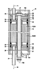
Reference is first made to Fig. 1, which shows a sectional view of the device
10. It should
first be noted that devices 10 of this type are known per se in the prior art,
i.e. in terms of
their fundamental construction, such that there is no need to go into specific
details with
regard to the description of the device 10. These devices 10 are used for
filtering and
separating liquid mixtures, wherein these liquid mixtures can be liquid or
gaseous mixtures.
The separation of the mixture 11 is obtained inside the device 10 by means of
membranes 12,
wherein these membranes 12 are polymer membranes known per se in the prior
art, which are
configured, e.g. for nanofiltration, ultrafiltration, or reverse osmosis.
The membranes 12 are received in a container 13, configured as a spiral wound
membrane
unit 34, as illustrated, e.g., in Figs. 4 and 5. The device 10 can also be
configured such that a
flat membrane unit 35 can be accommodated therein. The flat membranes 35 are
stacked on
top of one another, such that the liquid mixture 11 that is to be separated
normally passes
over the stacked membranes 12 in a meandering pathway, and exits the device 10
at the end
of the stack as a retentate 18, also referred to as a concentrate.
When a spiral wound membrane unit 34 is used in the container 13, the mixture
11 that is to
be separated is conveyed in parallel, axially through the entire coil of the
membrane, without
internal deflection over the entire spiral wound membrane, wherein all of the
retentate 18 also
exits the spiral wound membrane unit 34 axially here, and is conducted out of
the device 10.
The container 13 in which the spiral wound membrane unit 34, or the flat
membrane unit 35
is inserted axially at a first open end 13 in the course of assembly is
pressure-tight, such that,
8
Date Recue/Date Received 2021-11-11
e.g. it can withstand internal pressures in the interior 25 of the container
13 of more than 120
bar, by means of which the pressurized liquid mixture 11 is introduced via an
intake. These
high operating pressures continuously act on the interior 25 of the container
13 during an
intended operation of the device 10, wherein the liquid mixtures 11 introduced
therein are
conducted by means of this pressure over the membrane element 12. The
retentate 18 is
removed from the container 13 via an outlet 21. The container forms a tube-
shaped element,
and has a substantially circular cross section, wherein the circular cross
section provides the
container 13 with a good radial stability.
Although in theory all of the known membrane structures are suitable for use
in the device 10
according to the invention, so-called pillow membranes are used for the
membrane elements
12, i.e. pillow membranes are used for both the embodiment of the spiral wound
membrane
unit and the embodiment of the flat membrane unit, i.e. for the individual
pillow membranes
used therein. The pillow membranes characteristically have a discharge
opening, through
which the permeate generated and collected in the pillow is discharged, which
is the case
with both the membrane in the form of a spiral wound membrane unit as well as
for the
pillow membranes in a flat membrane unit.
In the embodiment of the device 10 according to Fig. 1, the permeate 16 is
collected in the
middle, and conveyed to an outlet 15, the permeate outlet, wherein the
permeate 18 is then
discharged from the device 10 for further use.
Specific to the device 10 illustrated herein is that the intake for the
mixture 11 that is to be
separated is formed on a first end element 19 at the top of the container,
that can be received
therein at a first open end 130, wherein the outlet 14 for the permeate
generated by or in the
membrane elements 12 is formed on a second end element 20 that can be received
in the
container 13 at a second opening 131. The outlet 21 for the membrane element
12, and thus
for the retentate 18 exiting the device 13 is likewise formed on a second end
element 20 that
can be received in the container 13 at a second open end 131.
The actual sealing pressure of the two end elements in the axial direction,
parallel to an
imaginary axis 132 passing through the container 13, which also forms the axis
for the
membrane unit 34, 35, or the tensioning bolt 37 passing axially through the
container 13, is
formed by first and second pressure elements 23, 24, wherein the two pressure
elements 23,
9
Date Recue/Date Received 2021-11-11
24 are placed on top of the first and second end elements 19, 20 at the
respective open ends
130, 131, such that they bear on the first and second end elements 19, 20,
respectively.
The module comprising the spiral wound membrane unit 34 or flat membrane unit
35
composed of membrane elements is secured in the interior 25 of the container
by means of a
respective retaining ring 26, 27, after this module is inserted into the
interior 25 through one
of the open ends 130, 131 of the container 13, including the respective end
and pressure
elements, which can be releasably secured in the interior 25 in a respective
circumferential
groove 28, 29 formed in the interior 25 of the container 13. In a simple
manner, the module
comprised of pressure elements, end elements, and the membrane units,
regardless of which
type of membrane units are used, is releasably secured in the interior 25 of
the container 13
by the retaining rings 26, 27.
A disk-shaped adjustment flange 30 is located between the retaining ring 26 at
the first open
end according to the illustration in Fig. 1 of the container 13, and the first
pressure element
23. The adjustment flange 30 has numerous axial threaded holes 31 parallel to
the axis 132 of
the container 13, in which corresponding adjustment screws engage. As a
result, the pressure
elements 23, 24 and thus the first and second end elements 19, 20 can be
slightly displaced
axially by turning the adjustment screws, such that the axial force applied to
the second end
element 20 and the second pressure element 24 through the axial displacement
of the screws
is ensured by a central axial tube in the spiral wound membrane unit 34, or by
an analogous
central, axial tube element if a flat membrane unit 35 is used.
The adjustment element 31 bears on the first circumferential groove 28 in the
interior of the
container 13. This is the upper or lower groove 28, 29 in Figs. 2 and 3,
respectively, which
show the first open end 130 in Fig. 2, and the second open end 131 in Fig. 3.
The end elements 19, 20, cf. the perspective illustration in Fig. 6, which are
substantially
plate-shaped, each have a groove 32 that encompasses their respective radial
circumference,
wherein this groove 32 accommodates a respective sealing element 33, cf. Fig.
1. The sealing
elements 33 have a sealing lip cross section, although the sealing elements
can also have
other cross sections. The tensioning bolt 37 passing axially through the
center of spiral
wound membrane unit 34, or the flat membrane unit 35, analogously, can have
axial grooves,
not shown herein, through which the permeate 16 collected in the middle is
conducted out of
Date Recue/Date Received 2021-11-11
the device 10. In the illustrations of the spiral wound membrane unit 34 in
Figs. 4 and 5, the
grooves themselves are formed in the central tensioning tube in the spiral
wound membrane
unit 34, such that the tensioning bolt 37 in this embodiment of the device 10
can have a
smooth surface, without any circumferential grooves. The flow of the permeate
16 is
indicated symbolically by the arrow in Fig. 1.
11
Date Recue/Date Received 2021-11-11
List of Reference Symbols
device
11 liquid mixture
12 membrane / membrane element
13 container
130 first open end
131 second open end
132 container axis
14 intake
outlet
16 permeate
18 retentate (concentrate)
19 first end element
second end element
21 outlet (retentate outlet)
23 first pressure element
24 second pressure element
interior (container)
26 retaining ring
27 retaining ring
28 inner circumferential groove (first)
29 inner circumferential groove (second)
adjustment flange
31 threaded hole
32 groove
33 sealing element
34 spiral wound membrane unit
flat membrane unit
36 membrane stack
37 tensioning bolt
12
Date Recue/Date Received 2021-11-11