Note: Descriptions are shown in the official language in which they were submitted.
CA 02714476 2010-09-10
1
Submersed device for reducing the polluting emissions
and saving energy in hydrocarbon combustion vehicles
The present invention essentially relates to the motor
vehicles, particularly those vehicles with internal-
combustion or diesel engines as well as all of the
apparatus that burn liquid hydrocarbons.
As it is well-known, the propulsors of the above motor
vehicles are not able to transform the whole mass of
the hydrocarbons into work and, as a consequence, a
portion of these hydrocarbons remains unburnt.
A number of solutions have been so far proposed to
overcome these problems and the related efforts have
regarded both the engine and the control electronics
with the result of a considerable increase in the
production costs and a continuous demand of servicing
to keep the apparatus under perfect operating
conditions, which is necessary to guarantee low
consumptions and reduced emissions.
it is also known from German Patent DE 4417167.6 a
device that, produces a composite emission of
electromagnetic waves and far infrared waves inside the
fuel tank including magnetic elements distributed along
and leant on an axial conductor provided with a diode
and pressed against the conductor by a cotton sheath or
so-called "sock".
However, this device has some drawbacks and
disadvantages which will be shortly illustrated
herebelow.
A first problem consists in that it is necessary to
CA 02714476 2010-09-10
2
inlet some radiant additive substances into the fuel
tank in order to obtain a sufficient propagation of the
far infrared waves. This. solution is only palliative as
the substance to be melt inside the fuel tends to clog
the conducts from the fuel pump to the engine.
Moreover, in the above-mentioned German Patent the
electromagnetic waves are caused to propagate by the
contact and the correct positioning of the balls and
the magnets located inside the device and held in their
positions just because of the compression of a cotton
"sock' which is wrapped around all of the elements and
contributes to reflect the waves. This is a source of
drawbacks as the cotton envelope tends to deteriorate
with time causing several problems among which:
IS - both the balls and the magnets lose their initial
position interrupting the electric connection to one
another and an internal copper wire ;
- the deterioration of the cotton causes the loss of
its reflecting efficiency;
the deteriorated cotton loses its capability of
filtering external agents;
- the deteriorated cotton can fray causing further
possibilities for the conducts from tank to engine to
become clogged.
Therefore, it is self-evident that the device disclosed
in the above-mentioned German Patent cannot in any way
be used in the practice first of all because its
operation capability changes with time and then because
it could cause damages to the vehicle.
This invention seeks to overcome these problems by
CA 02714476 2010-09-10
3
providing a device which does not need any servicing,
is easy to be installed without modifying in any way
the fuel pump system of the vehicles, and operates
inside the mass of the fuel in the fuel tank.
This has been accomplished by a device to be submerged
inside the fuel tank which is capable of producing an
emission of far infrared electromagnetic waves so that
both its function and structure still remain unchanged
in time without the use of additives in the fuel.
The composition of the materials which the different
parts of the device consist of and their space
distribution are such as to increase the production of
electromagnetic waves and far infrared rays so that the
energy associated to these electromagnetic waves, which -
spread throughout the fuel, interacts with the
hydrocarbon molecules and temporarily modifies their
structure in order to make them more easily
vaporizable. This advantageously increases and improves
the combustion, ensuring that most of the previously
unburnt fuel will be burnt. Advantageously, this causes
the polluting emissions as well as the consumption to
reduce considerably and the engine to be better cleaned
and its performance to be more effective.
A better understanding of this invention will ensue
from the following detailed description with reference
to the accompanying drawings which illustrate a
preferred embodiment only by way of a not limiting
example.
317
CA 02714476 2010-09-10
4
In the drawings:
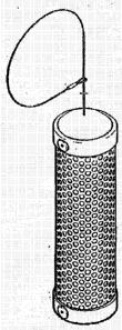
Figure 1 is an external perspective view of the
invention;
Figures 2 to 5 are elevation views of the four sides of
the device;
Figures 6 and 7 are partially sectioned perspective
views which show the arrangement and the structure of
the internal parts of the invention;
Figures 8 and 9 show the installation of the device
inside the fuel tank.
zs
As already mentioned, the device according to this
invention temporarily modifies the molecular structure
of the hydrocarbons contained in the liquid fuel and
acts as a fuel vaporization accelerator.
In particular this is accomplished by energising the
fuel molecules by the emission of far infrared rays,
which are generated by the synergical action of the
electromagnetic fields generated by permanent magnets
6, the ceramic material contained inside ceramic
sleeves 4 and ceramic balls 5 as well as the kinetic
energy of the fuel during the running of the vehicle,
and the current generated in the device by the ioils
inside the fuel.
The infrared rays are formed by electromagnetic waves
characterized by a wave length between 0.76 e 1000 inn
CA 02714476 2010-09-10
~J.
and are furthermore divided into "near", "middle", and
"far" infrared according to the following tablet
INFRARED RAYS (IR) WAVE LENGTH (tun)
NLAR from 0.76 to 2.5
MIDDLE over 2.5 up to 26
FAR over 25 up to 1000
Far infrared rays are known for their capacity of
generating chemical and physical transformations in the
structure of any material.
The device according to this invention has a
cylindrical form and consi'sts of an external tube 3
perforated by a number of holes and preferably made of
silver-plated bronze with two caps at its ends, an
anchoring wire 1 being bound to one cap 2 (see figures
1-5). Such anchoring wire 1 is secured to the device by
a hinged member which permits it to rotate without
1s entangltg the wire.
A complex assembly consisting of a preferably stiff,
central copper wire 9 is disposed inside this
perforated tube 3 at the middle of which a diode 10 is
soldered, as it may be seen in figures 6 and 7. Such
copper wire 9 is put with its whole length inside a
conduct formed by a plurality of sleeves 4 of ceramic
material alternated to ring-shaped permanent magnets 6.
Some further balls 5 made of ceramic material are
located outside such sleeves 4 and magnets 6.
According to a particular characteristic of the present
CA 02714476 2010-09-10
6
invention, copper wire 9, sleeves 4, magnets 6, and
balls 5 are electrically connected to one another.
The complex assembly of the device is also provided
with a ceramic cotton "sock 7 enclosed inside a
ceramic filter consisting of a metal net 8 completely
wrapped around the whole assembly.
As mentioned above, the assembly described above is
located inside the perforated metal tube 3 and then
closed at its both ends by two caps 2. It should be
noted that the continuity of the electric connection
among ceramic cotton, metal net, and outer perforated
cylinder also guarantees the electric connection
between the latter and the above-mentioned copper wire
9 to which diode 10 is connected.
The various components of the device will thereafter be
described in greater detail in order to better disclose
the characteristics and the peculiarities that
distinguish the present invention.
The outside perforated tube 3 is made of bronze and has
a silver coating. The choice of these materials has a
dual function: bronze avoids rust while silver
increases the purifying effects towards external
aggressive chemical agents.
Metal net 8 sprayed with a ceramic composition has the
function of keeping all of the elements contained in
its interior in the right position.
Cotton "sock" 7 aiming at both preventing external
agents from entering the device and spreading the
emitted waves has a very strong and unalterable
weaving, and is provided with an inner layer that is
CA 02714476 2010-09-10
7
soaked with platinum powder during the final phase of
weaving.
Magnetic rings 6 are made of permanent magnetic
material including rare earth elements such as samarium
(Sm) and cobalt (Co). These magnets belonging to the
last generation have far higher performances than any
other magnet currently available, in particular the
high energy and magnetic power of samarium allow very
compact and highly efficient magnets to be designed.
These permanent magnets 6 interact synergically with
sleeves 4 and balls 5 of ceramic material and increase
the emission of electromagnetic waves in the far
infrared field, which is very important for their
=spreading. The combination of magnets and ceramic
materials is essential to enhance the chemical effects
of their components. The magnets could also have other
forms, for example balls, tablets and so on.
Sleeves 4 of ceramic material are made by moulding
followed by a baking for many hours at a temperature of
about 1200 C. Such ceramic material is baked six times
and then cooled by natural air.
The ceramic material of sleeves 4 produces far infrared
rays, its efficiency being based on its anti-corrosive
property which prevents rust from being developed.
Ceramic balls 5 increase the production of such far
infrared rays.
Ceramic balls 5 are moulded and then baked at 500-
600 C. Their main function is to extend the effects of
ceramic sleeves 4 throughout the device. In the
so illustrated embodiment, the ceramic materials used for
CA 02714476 2010-09-10
8
ceramic sleeves 4 and for ceramic balls 5, mainly
include sic, TiO2, Cr203, A1203, Fe, and the
manufacturing method includes essentially the following
steps;
- providing a mixture by spraying liquid on the parts
to be mixed;
drying
moulding (by compression)
baking;
- final shaping and cleaning;
- packaging.
The device is placed inside the fuel tank so as to hang
inside therein, as shown in figures 8 and 9, and is
connected to wire 1 which is provided with a hinge
member.
The composite electromagnetic waves which are being
formed are emitted towards the internal walls of the
fuel tank through ceramic cotton 7 and through metal
net 8. The quality of the fuel is gradually improved by
the emission of electromagnetic waves. In other words
fuel is purified so that it can burn very quickly
without producing heavy smokes and/or particulate, etc.
This means that the liquid fuel inside the fuel tank
undergoes a temporary modification of its molecular
structure so that the latter can be quickly vaporized
by the composite wave.
In other words, considering for example fuels such as
gasoline or diesel oil characterized by complex chains
of carbon and hydrogen atoms, the latter are broken by
the composite wave generated according to the present
CA 02714476 2010-09-10
9
invention. These chains are interrupted at their
carbon-carbon bonds and their hydrogen-hydrogen bonds
giving rise to chains which are more suitable for a
better combustion.
This is also the case for all of combustibles and
liquid fuels originating from hydrocarbons.
According to the present invention, when the fuel
inside the fuel tank is shaken by the vehicle's
movement, the static electric charges (ions) produced
inside are transferred to diode 10 through central
copper wire 9 in order that the electric charges
accumulate between the conduct formed by ceramic
sleeves 4, ring magnets 6, and diode 10 acting as an
electrode.
The above-mentioned diode 10 helps to concentrate the
flow of the electromagnetic waves, and further causes
the production of far infrared waves to be maintained.
In this way ceramic sleeves 4 emit far infrared rays
and ceramic balls 5 help to spread them-
The change of the molecular structure of the fuel
causes a weakening of the reciprocal molecular
aggregation, giving rise to a better as well as greater
permeation of the oxygen between the molecules of the
hydrocarbons.
All this brings several advantageous consequences among
which:
- drastic reduction of unburnt hydrocarbon emissions;
- reduction in consumptions;
- the engine fuel supply system is cleaner;
- better efficiency and performance of the engine
CA 02714476 2010-09-10
to
less request of servicing.
Furthermore, the engine fuel pump system is in no way
altered or changed as the device is installed inside
the fuel tank, and the lack of external supply totally
eliminates any possibility of explosions due to short
circuit.
Experimental tests have demonstrated that the use of
this device reduces fuel consumptions by 10 - 25%,
depending on the type of engine and its wear.
Finally, it should be noted from the above description
that this invention can be applied without
modifications to any motor vehicle burning liquid
hydrocarbons since only a minimum oscillation movement
(vibration} of the vehicle is requested.
It should be appreciated that such movement is
essentially given by the movement of the vehicles or,
in case of engines of still devices, by the vibrations
produced during the operation thereof.
The present invention has been described and
illustrated according to a preferred embodiment
thereof, however, it should be understood that those
skilled in the art can make equivalent modifications or
zeplacements without departing from the scope of the
present industrial invention.