Note : Les descriptions sont présentées dans la langue officielle dans laquelle elles ont été soumises.
CA 02218429 1997-10-15
DEVICE AND METHOD FOR COMMINUTION
Field of Invention
This invention relates to the comminution of raw materials
like wood chips, glass and rocks into fine powder.
Background of Invention
Numerous attempts have been made for comminuting raw
material into fine powder. One problem with such attempts is
their susceptibility to jamming and their inability to produce
uniform results.
Summary of Invention
There is disclosed a device for comminuting raw material
comprising: (a) a pan with a bottom and circular interior wall
centered about a central axis; (b) a lid profiled to engage
tightly said pan at their respective peripheries, whereby said
pan and said lid define a comminution chamber centered about said
central axis; (c) input means, located upstream of said
comminution chamber, for receiving and guiding the raw material
to said comminution chamber; (d) a first longitudinal blade
disposed rigidly downwardly from said lid, extending outwardly
from said central axis; (e) propelling means, disposed within
said comminution chamber, for propelling the raw material from
input means radially towards impact against said blade and then
against said pan wall; (f) forced air flow means for creating an
upward flow of air to lift raw material after impacting said pan
wall, out of said comminution chamber; and (g) output means for
outputting the raw material so lifted.
There is also disclosed a device for comminuting raw
material comprising: (a) a pan with a bottom_and circular
interior wall centered about a central axis; (b) a lid profiled
to engage tightly said pan at their respective peripheries,
whereby said pan and said lid define a comminution chamber
centered about said central axis; (c) input means, located
upstream of said comminution chamber, for receiving and guiding
the raw material to said comminution chamber; (d) a first
A 235727-1/MMY
CA 02218429 1997-10-15
- 2 -
longitudinal blade disposed rigidly downwardly from said lid,
extending radially from said central axis; (e) a plurality of
impeller blades for sucking the air inwardly toward the central
axis; (f) a plurality of scythe blades rigidly attached to said
plurality of impeller blades; (g) a plurality of stator blades
rigidly attached to bottom of said pan; (h) rotating means to
rotate said plurality of scythe blades over said plurality of
stator blades; (i) forced air flow means for creating an upward
flow of air to lift raw material after impacting said pan wall
out of said comminution chamber; and (j) output means for
outputting the raw material so lifted.
Brief Description of Drawings
Advantages of the present invention will become apparent
from the following detailed description taken in conjunction with
preferred embodiments shown in the accompanying drawings, in
which:
Fig. 1 is a side view, partially broken away, of a device
incorporating an embodiment of this invention;
Fig. 2 is a sectional plan view taken along line 2-2 of Fig. 1;
Fig. 3 is a sectional side view taken along line 3-3 of Fig. 2;
Fig. 4 is a plan view taken along lines 4-4 of Fig. 3;
Fig. 5 is a plan view of the pan of the device of Fig. 1;
Fig. 6 is a side view of the separator of the device of Fig. 1;
Fig. 7 is a plan view of the flow of injected air seen from line
7-7 of Fig. 3;
Fig. 8 is a sectional view of the flow of injected air and raw
materials seen from line 8-8 of Fig. 7;
Fig. 9 is a sectional view of the flow of injected air seen from
line 9-9 of Fig. 7; -
Fig. 10 is a sectional view of the flow of injected air seen from
line 10-10 of Fig. 7;
Fig. 11 is a sectional view of a device incorporating another
embodiment of this invention;
Fig. 12 is a truncated plan view of the impeller and scythe blade
assembly of the device of Fig. 11;
A 235727-1/NMY
CA 02218429 1997-10-15
- 3 -
Fig. 13 is a truncated plan view of the stator blades of the
device of Fig. 11.
Detailed Description of the Preferred Embodiments
A device for comminuting raw material will be explained and
thereby a method of comminuting raw material will become evident
as the operation of the device is explained.
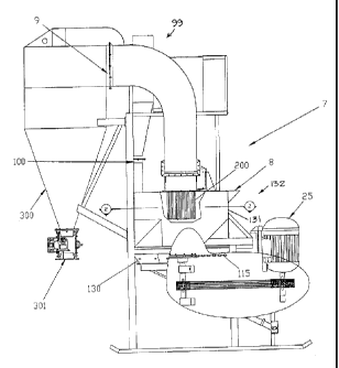
As seen in Figs. 1 and 3, comminution device 7 has input
chute 8 for raw material and an output 9 for comminuted raw
material. Main body 132 of device 7 is the combination of pan
130 and lid assembly 131. Conventional forced air means or
blower 99 is connected to main body 132 at inlet 100. The bottom
of lid assembly 131 and pan 130 form comminution chamber 10 where
the comminution occurs.
Downstream of comminution chamber 10 are output 9,
conventional cyclone 300 and output gate valve 301, and they,
with conventional input gate valve (not shown) connected to input
8, maintain intrinsic air pressure of the system. Blower 99
recycles air from cyclone 300.
Main body 132 has a central axis about which central shaft
116 turns and about which separator 200 and comminution chamber
10 are centered.
As shown in Figs. 2 to 4, deflecting cone 20 is a hollow,
inverted and open cone and is disposed by struts 23, about the
central axis, with apex pointing upwardly. Cone 20 is disposed
centrally within the hollow of inverted, hollow frusto-conical
cone 21, creating an annulus of separation 22 for the raw
material from input 8 to fall through.
At the bottom of lid assembly 131 is a metal plate to which
eight shear blades 120 are rigidly disposed tangentially and
equispaced from a central octagonal hub centered on the central
axis. Blade 120 is disposed about 61° from the horizontal
downwardly in the circular direction of rotation of chains 115
(as indicated in Fig. 4). Blade 120 (viewed from the side as
shown in Fig. 3) has an inner edge 120A (proximate annulus 22)
and a bottom edge 120B.
A 235727-1/MBfY
CA 02218429 1997-10-15
- 4 -
Pan 130 is hinged to one side of lid assembly 131 and is
provided °~ith sealing features so that when it is raised to meet
the bottom of lid assembly 131 at their respective peripheries
and secured by fasteners, an air-tight seal is created for
comminution chamber 10. Pan 130 may be opened for cleaning and
replacing blades 120 and like activities. For economy of
illustration, the hinging mechanism, sealing and fasteners are
conventional and are not shown.
As best shown in Fig. 5, eight wall plates 125 are disposed
circumferentially about the interior periphery of pan 130 to form
the interior wall thereof. Each plate 125 is disposed at about
45° from the horizontal bottom of pan 130. The interior of pan
130 is essentially circular and precisely octagonal and can be
made more smoothly circular by conventional means (for example,
using more and smaller wall plates). To avoid corners where raw
material may lodge, plates 125 may be bevelled on their sides and
top to produce a flush surface with respect to each other and the
bottom of pan 130 (as shown in Fig. 11).
Nine multi-link chains 115 are conventionally secured at
their respective inner ends to central shaft 116 but are
otherwise loose to be rotated quickly. Chains 115 are
conventional chains with thirteen 13 links, each link of about 2"
long, so that the length of a chain 115 is about 22".
Motor 25 rotates central shaft 116 through conventional belt
and pulley arrangements. The chains 115 spin with tip speeds of
about 500 mph, to form a spinning circular "curtain" of metal to
move outwardly and accelerate the raw materials falling thereon
from annulus 22.
It has been found that nine chains 115 is a suitable number
for a comminution chamber 10 dimensioned where pan 130 is about
4' in diameter and 10" in height. Generally, it has been found
that the greater the number of chains, the greater efficiency of
comminution but this is subject to increased risk of entanglement
of the chains when rotated.
Air is injected into device 7 through inlet 100 by blower
99, which can inject air in the order of 10,000 to 15,000 cubic
A z35~z~-yhrnr
CA 02218429 1997-10-15
- 5 -
feet per minute. To minimize the adverse effects of heating on
the comminution process (described below), cooled air may be
injected into the flow stream or the raw material may be pre-
cooled before being inputted into the input chute 8; both being
accomplished by conventional means (not shown).
Raw material is dropped into input 8 and slides down to fall
centrally through annulus 22 and to be then deflected outwardly
by cone 20. The raw materials are then propelled outwardly as
follows. The raw materials hit the circular "curtain" formed by
rotating chains 115, and are then propelled outwardly
centrifugally with great acceleration towards wall plates 125 of
''pan 130. The raw materials vertically and violently bounce
,between the curtain formed by spinning chains 115 and the bottom
of lid assembly 131, and also horizontally impact violently
against blades 120 as they move outwardly towards wall plates 125
of pan 130. The raw materials then impact violently against the
wall plates 125 of pan 130 at high speeds. These violent impacts
accomplish comminution of the raw material by shattering and
similar disintegration.
Rotating chains 115 do not normally impinge on any part of
comminution chamber (i.e. unless there is a collision with raw
material which distorts temporarily the orbit of chains 15).
Chains 115 rotate with clearance of about 2" from the bottom of
pan 130, of about 1" from blades 120 and, (from the outer free
tips of chains 115) of about 1" from plates 125.
Although chains 115 are shown, similar forms of agitator
elements are possible (such as blades and disks with perforations
and protuberances), as long as they are useful when rotated to
impact violently the raw material and to propel outwardly.
The flow of air is shown in Figs. 7 to 10, which (with the
exception of Fig. 8) are simplified by omitting details not
directly applicable to the illustration of a certain aspect of
the air flow.
Forced air enters comminution chamber 10 from blower 99
through inlet 100. The air is then channelled into two downward
flows (150 and 151) and then four flows travelling downwardly
A 235727-1/MMY
CA 02218429 1997-10-15
- 6 -
through four vertical corners equispaced about pan 130. The four
jets of air are directed equispaced and downwardiy approximately
tangential to the circular assembly of wall plates 125 of pan
130, as seen in Fig. 7. Thus a fast moving "torus" or toroidal
pattern of air is created within pan 130 (shown in plan cross
section in dotted arrow in Fig. 7 and in side cross section by
the dotted circle in Fig. 11). The toroidal flow pattern
dissipates approximately as follows. The air partially circles
pan 130 and then rises to create a fast moving annular column of
air along upward flow lines 152 rising along the inside the side
wall of lid assembly 131 which carries therewith the raw
materials after impact with pan wall plates 125.
For ease of illustration and understanding, downward flow
151 will be described below but downward flow 150 will not
because it is similar to flow 151 except it is on the other side
of the device.
Flow 151 is channelled to flow 151 and 151A (as seen in
Figs. 7, 9, and 10). The materials, after impacting said pan 130
wall, are swept upwardly along the walls of lid assembly 131,
along flow lines 152 above annulus 22 and then redirected
inwardly and downwardly by redirectional turn 110 towards annulus
22 (i.e. directed back to comminution chamber 10). Turn 110 is
the upper half of a torus tube which extends about the periphery
of the lid assembly 131 and operates to filter the material as
follows. Some of the heavier material descends through annulus
22 to enter comminution chamber 10 again, as represented by flow
lines 153, to participate in another cycle of comminution. The
lighter material (in spite of being directed downwardly by turn
110) rises towards separator 200. Some of the material does not
pass through separator 200 falls down (as wilh be explained
below) and joins the heavier material, as indicated by flow lines
153. Also, the centrifugal effect of turn 110 on the material
also serves to move the heavier particles from the lighter
particles of the material to the outside, i.e. produces a
separating effect between heavier and lighter particles of the
materials. The closer the inner edge of turn 110 is to annulus
)1 235727-1/MMY
CA 02218429 1997-10-15
22 (i.e. the longer downwardly the material must travel before
being able to rise), the finer the filtering effect.
As shown in Fig. 8, separator 200 separates from the raw
material rising along flow lines 152 from the periphery of pan
130 which have not dropped into annulus 22. Raw material of a
prescribed particle size or less move into the interior of
separator 200 and proceed to output 9. Material whose particle
size is larger than said prescribed particle size, bounce back
from separator 200 and into annulus 22, as shown in flow lines
153.
As shown in Fig. 6, separator 200 is of a conventional
trommel construction and includes a squirrel cage 205 which is
rotated by variable speed motor 210. Cage 205 has thirty six,
circumferentially spaced and equispaced vertical blades 206.
Blade 206 is a 18" x 1" x 1/8" rectangular plate and each blade
206 is disposed about 5° from the radial against the direction of
rotation. By adjusting the speed of motor 210, the desired
particle size can be obtained. The faster the rotation, the
finer the output particles will be emerging from separator 200
towards output 9.
Raw materials include glass, oyster and crab shells, cement
clinker rock, quartz rock and wood chips. For example, cement
clinker rock of 1.5" diameter has been comminuted to 500 mesh
particles on two cycles through comminution chamber 10. Quartz
rock of 1.5" diameter has been comminuted to 450 mesh particle on
two cycles. Wood chips of size 1" x 2" x 1/4" has been
comminuted to 40 mesh in one cycles and 85 mesh in two cycles.
Dolomite of 3/4 inch pebbles can be continuously processed. Most
of the dolomite raw material is outputted as 350 mesh powder
within the first cycle. Raw materials include also waste
materials (including heterogenous materials found in municipal
and household garbage debris), where the comminuted result has
less moisture content than the inputted raw material.
Blades 120 are made of AR QT 350 steel. Plates 125 are made
of AR QT 350 steel. The links of chain 115 are made of hard
steel which does not stretch, perhaps 70 grade steel.
A 235727-1/MMY
CA 02218429 1997-10-15
_ g _
Another embodiment of the invention is shown in Figs. 11 to
13, in which the device of Fig. 11 basically corresponds to the
device of Fig 8, except that cone 20 is raised relatively and
chains 115 are replaced with another structure (as will be
explained next). Otherwise, the other components are identical
and for economy of description, will not be described again.
Circular cradle 350 consists of forty rigid extensions or
wings 321 radially extending from the center thereof (shown in
truncated form in Fig. 13). Mounted rigidly to each wing 321 is
a pie-shaped stator blade 320 (two of which are shown in Fig.
13) .
Cradle 350 is mounted on a platform composed of eight
radially extending shoulders or webs 351. A triangular wedge 355
is placed between each shoulder 351 (one such wedge 355 is shown
in Fig. 13), so as to create a shallow cone, to guide the
material falling thereon towards the periphery of pan 130 where
the toroidal flow of circulating air is (as seen in side view in
Fig . 11 ) .
Twenty impeller blades 310 are rigidly connected to forty
scythe blades 315, as shown in Fig. 12, and the impeller-scythe
blades assembly thereof is rotated by central shaft 16). The
outer tip speed of the scythe blades 315 (i.e. proximate the wall
of pan 130) is about 250 mph. The assembly rotates above the
stationary stator blades 320 with a small clearance, in the order
of 1/32" or less. Impeller blade 310 may be a simple wedge (as
shown in side view in Fig. 12), with apex pointed in the
direction of rotation.
Mounted rigidly on the periphery of cradle 350 is upper
circular skirt 330 and lower circular skirt 331. Upper skirt 330
prevents materials from escaping from the impeller-scythe blades
assembly when rotating. Lower skirt 331 forces materials
downwardly to join the toroidal pattern of air within pan 130, so
as to obtain maximum speed and subsequent uplift of the column of
rising air 152.
The air flow patterns are similar to those described with
the embodiment of Figs. 1-4 and will not be repeated for economy
11 235727-1/MMY
CA 02218429 1997-10-15
- 9 -
of description. One difference is the result of impeller blades
310. Instead of immediately contacting pan 130, air flow 151A is
sucked inwardly towards the center of the impeller-scythe blades
assembly by the rotating impeller blades 310. Material is caught
by flow 151A and flows through the cutting and related
disintegrating activity of scythe blades 315 rotating above
stator blades 320. The raw material is then sucked upwardly with
the rising column of air 152.
Except for the differences in components and air flow
described above, the components, operation, air flow and general
principles of the embodiment show in Figs. 1-4 are the same as
for this embodiment and are not repeated for economy of
description.
It has been found with this embodiment that rubber raw
material in the form of tire buffings and crumb rubber, can be
comzninuted to fine powder of less than 300 mesh particle size.
Impeller 210 blades are made of QT 100 steel and may be
about 12" long. Scythe blades 215 are made of QT 360 steel and
have a cutting length of about 16". Stator blades 220 may be
made of a hard metal, like nickle-cadmium alloy with 65 Rockwell
hardness. Stator blades 220 have length dimensions similar to
scythe blades 215.
The actual dimensions of components, the number of blades,
the number of links in the chain, the number of chains, the
rotational speeds, the clearances of the chains within the
comminution chamber and the like of components of representative
examples of the invention are given above. It will be
appreciated that they are given merely for purposes of
illustration and are not limiting in any way. The specific
parameters may be varied as long as the principles are respected.
For example, the desired speed of the forced air is a function of
the specific gravity of raw material and the rotational speed of
chains. For another example, depending on the raw material, the
number of blades and chains may be adjusted to produce optimal
results.
11 235727-1/MMY
CA 02218429 1997-10-15
- 10 -
While the principles of the invention have now been made
clear in the illustrated embodiments, there will be immediately
obvious to those skilled in the art, many modifications of
structure, arrangements, proportions, the elements, materials and
components used in the practice of the invention, and otherwise,
which are particularly adapted for specific environments and
operational requirements without departing from those principles.
The claims are therefore intended to cover and embrace such
modifications within the limits only of the true spirit and scope
of the invention.
A 23577-1/MMY