Note: Descriptions are shown in the official language in which they were submitted.
CA 02609396 2007-11-23
WO 2006/130977 PCT/CA2006/000933
APPARATUS AND PROCESS FOR THE PYROLYSIS OF AGRICULTURAL
BIOMASS
Field of the Invention
The invention relates to the pyrolysis of agricultural biomass. More
particularly,
the invention relates to an integrated combustion chamber and fluidized bed
pyrolysis
reactor that is compact and particularly well suited to mobile operation. A
lift tube in
fluid communication with the pyrolysis reactor is located within the
combustion chamber
for circulating biomass and an inert fluidizable media upwardly therethrough;
this
advantageously increases heat transfer and leads to more rapid pyrolysis. The
apparatus and process are especially well suited to the pyrolysis of low
density
agricultural biomass.
Background
Fast pyrolysis is a high temperature process (350 to 800 C) in which a
biologically based feedstock is rapidly heated in the absence of air and
vaporizes into a
product gas stream. Although the smoke-containing gas stream that is produced
comprises both combustible and inert components, of greater interest is a
liquid product
that is usually condensable therefrom. One common oily liquid product that may
be
condensed from the product gas stream is dark brown in colour and may be
burned as
a bio-oil having a heating value of about half that of conventional fuel oil.
Other liquid
products can contain, for example, flavour enhancing constituents or even
pharmaceutically active compounds. The char and ash remaining after pyrolysis
can
also have value as fuel or chemical feedstocks.
The characteristics of the liquid product depend upon the biological feedstock
being used and the processing conditions. In fast pyrolysis, reactions
typically take
place in less than 3 seconds and are carefully controlled to provide the
desired product
characteristics. Fluid bed reactors are often used to provide rapid heat and
mass
transfer and inert solid carriers (eg: silica sand) are sometimes used as an
aid in heat
transfer and biomass processing. These fluidized bed fast pyrolysis processes
are weil
documented and have been used in many different applications for several
decades.
See, for example, Bridgwater, A.V.; Peacocke, G.V.C. "Fast pyrolysis processes
for
1
CA 02609396 2007-11-23
WO 2006/130977 PCT/CA2006/000933
biomass" Renewable and Sustainable Energy Reviews, v. 4 (2000), pp. 1-73, for
a
review of prior art fluid bed fast pyrolysis processes developed over the last
20 years.
Low density agricultural biomass (eg: straw, stalks, husks, chaff, bark, wood
chips, etc.) is typically widely dispersed within a given geographical area,
difficult to
collect and expensive to transport economically. In the fast pyrolysis of low
density
agricultural biomass, a common problem that makes the process uneconomical is
the
prohibitive cost of transporting these bulky materials to a central processing
site.
Application of fluid bed fast pyrolysis technology to such materials therefore
relies upon
a significant reduction or elimination of these material transportation costs.
It would be
desirable to provide "self contained" fast pyrolysis process equipment that is
compact,
mobile and has the ability to be set up and operated close to the source of
the feed
materials. To make it easier for farmers and workmen, particularly in the
developing
world, to take advantage of such mobile equipment, it would also be desirable
that the
equipment be simple to operate and flexible in terms of the choice of fuel
source. The
process employed in using the equipment should be forgiving in terms of
particle size
and biomass moisture content. The process should also take advantage of rapid
heat
transfer and short solids residence time to reduce vessel size and increase
throughput.
US patents 5,728,271 and 5,853,548 disclose a thermolysis process for
liquefaction of biomass solids employing separate combustion and fluidized bed
reaction vessels. The process takes place at low temperature and employs long
residence times. This process is therefore not suitable for mobile
implementation.
US patents 6,048,374 and 6,830,597 disclose a pyrolysis process for gasifying
and/or liquefying biomass that employs combined fluidized bed and combustion
reactors. The fluidized bed reactor is in the form of a tube and biomass moves
downwardly through the tube. The combustion chamber partially surrounds the
reactor
tube and heat from the combustion chamber passes through the reactor wall and
directly heats the biomass within the interior reactor tube. The reactor is in
communication with the combustion chamber through a bottom opening that allows
char to be consumed in the combustion chamber as fuel. The reactor does not
contain
any fluidizabie media and no fluidized bed is employed, which limits heat and
mass
transfer within the reactor.
2
CA 02609396 2007-11-23
WO 2006/130977 PCT/CA2006/000933
US patents 5,792,340 and 5,961,786 disclose fast pyrolysis processes for the
production of a liquid product containing flavour enhancing constituents. The
processes employ a fluidized bed transport reactor that utilizes gas
velocities high
enough to cause biomass and an inert heat carrying media to move upwardly
within the
reactor. The biomass and inert carrier are separated from the product gas
stream by a
cyclone and re-introduced into the bottom of the bed. The combustion chamber
is
separate from the reactor. Although this configuration leads to rapid mass
transfer, it
requires careful control of particle size, is complicated to operate and is
not well-suited
to mobile implementation due to its size and energy requirements.
US patent 4,917,028 discloses a pyrolysis reactor that includes an interior
drying
zone where biomass moves downwardly, a lower combustion zone where heat is
added and where biomass particles are conveyed upwardly, and an outer
pyrolysis
zone where biomass is fluidized and is deflected back towards the interior
drying zone
to rain down upon the biomass therein. This reactor does not employ lift tubes
but
rather circulates the entire bed between the combustion chamber and pyrolysis
reactor;
as a result, there is both fluid and soiid communication between the zones,
which
makes it difficult to precisely control process conditions and achieve the
desired product
characteristics.
To date, conventional fast pyrolysis processes employ multiple vessels, are
complex to operate, are inflexible and/or are not suitable for mobile
operation.
Compact systems that combine the combustion chamber and pyrolysis reactor in a
single vessel usually involve mixing of fluids and/or solids between the two
portions of
the vessel; this leads to contamination and/or destruction of the most
valuable
condensable liquid products in the product gas.
The need therefore exists for an improved apparatus for pyrolysis of low
density
agricultural biomass and a process for use thereof.
Summary of the Invention
According to an aspect of the present invention, there is provided an
apparatus
for the pyrolysis of agricultural biomass comprising: a fluidized bed
pyrolysis reactor; a
combustion chamber; a lift tube located within the combustion chamber and in
fluid
communication with the pyrolysis reactor, the lift tube having a lower inlet
and an upper
3
CA 02609396 2007-11-23
WO 2006/130977 PCT/CA2006/000933
outlet; and, a nozzle located within the lift tube proximal the inlet for
educting a first inert
fluidizable media located within the pyrolysis reactor upwardly through the
lift tube.
According to another aspect of the present invention, there is provided a
process
for the pyrolysis of agricultural biomass comprising: providing an apparatus
as
described above; creating heat through combustion of fuel in the combustion
chamber;
fluidizing the first inert fluidizable media in the fluidized bed pyrolysis
reactor using a
low oxygen content gas; introducing the biomass into the pyrolysis reactor;
educting the
biomass upwardly through the lift tube with the first inert fluidizable media;
transferring
the heat from the combustion chamber into the biomass in the lift tube;
exiting the
heated biomass from the lift tube outlet into the pyrolysis reactor; and,
circulating the
heated biomass downwardly through the fluidized bed in the pyrolysis reactor.
The combustion chamber may have a common surface with the pyrolysis
reactor. The combustion chamber may be cylindrical and the pyrolysis reactor
may be
located within an annular space about the combustion chamber. In this case,
the
common surface may then be an annular wall located between the pyrolysis
reactor
and the combustion chamber. The pyrolysis reactor may be divided into one or
more
chambers within the annular space and/or may contain one or more baffles to
promote
mixing or to help direct either biomass or the inert fluidizable media in a
desired
direction. The bottom of the pyrolysis reactor may comprise a fluid
distributor. The fluid
distributor may comprise a plate having a plurality of holes and may include
means to
prevent plugging of the holes by the fluidizable media, the biomass, char, or
a
combination thereof. The plate may be flat or may be frustoconical in shape in
order
that the material in the pyrolysis reactor moves inwardly and downwardly
toward the lift
tube iniet(s).
The combustion chamber may be located within an interior of the apparatus.
Any suitable fuel may be burned to create the required heat; for example, the
fuel may
comprise a gaseous fuel (eg: natural gas or propane), a liquid fuel (eg:
diesel fuel), or a
solid fuel (eg: wood, coal, etc.). The conditions within the combustion
chamber may be
carefully selected to produce the most efficient utilization of the fuel, and
these
conditions may be adjusted depending upon the fuel being used. In order to
provide
optimal selection of conditions, there is preferably no communication of
fluids and/or
solids between the combustion chamber and the pyrolysis reactor.
4
CA 02609396 2007-11-23
WO 2006/130977 PCT/CA2006/000933
The apparatus may comprise a pluraiity of lift tubes and the lift tubes may be
uniformly spaced apart within the combustion chamber. The combustion chamber
is
designed to deliver a maximum amount of heat to the biomass, both in the
pyrolysis
reactor and in the lift tube(s). The lift tube(s) may be finned to increase
the rate of heat
transfer into the tube(s).
The combustion chamber may comprise a fluidized bed containing a second
inert fluidizable media provided to increase heat transfer to the tube and/or
the pyrolysis
reactor. The second inert fluidizable media may be identical to the first
inert fluidizable
media, or may be specially selected based on conditions in the combustion
chamber.
There is preferably no circulation of the inert fluidizable media between the
combustion
chamber and the pyrolysis reactor. A fluid distributor may be provided within
the
combustion chamber. The fluid distributor may comprise a plate containing a
plurality
of holes. The plate may be continuous with the plate used as a fluid
distributor in the
pyrolysis reactor or may be separable therefrom.
The outlet of at least one of the lift tubes may comprise a directional device
for
directing the first inert fluidizable media exiting from the lift tube toward
a pre-
determined location within the pyrolysis reactor. The directional device may
comprise a
baffle, an angled deflector plate, an elbow, a duct or other suitable
structure. The first
inert fluidizable media may be directed laterally and/or downwardly relative
to an exit
direction of the media from the outlet. This may be achieved either through
the design
of the outlet, the location of the directional device, the design of the
directional device,
or a combination thereof. The biomass may exit the lift tube into a freeboard
area of
the pyrolysis reactor.
In one embodiment, the biomass is directed downwardly into the fluidized bed.
This may be achieved upon introduction of the biomass to the reactor and/or
upon exit
of the biomass from the lift tube. The biomass may be introduced into the
reactor
through the directional device for entrainment with the first inert
fluidizable media exiting
the lift tube; in this manner, the biomass may be carried downwardly by the
media to
exit the directional device within the fluidized bed. The pyrolysis reactor
may include a
suitable opening provided for the introduction of biomass without permitting
ingress of
oxygen in order to preserve pyrolysis conditions within the reactor. The
opening may
comprise an airlock solids feeder (eg: a screw type or rotary solids feeder).
The
5
CA 02609396 2007-11-23
WO 2006/130977 PCT/CA2006/000933
opening may admit the biomass directly into one or more directional devices
located
within the pyrolysis reactor.
The nozzle is provided to entrain both the first inert fluidizable media and
the
biomass within the lift tube. The nozzle body may be located outside of the
lift tube, so
long as the nozzle opening is within the lift tube. The nozzle is designed to
produce a
region of low pressure relative to the bottom of the bed in order to draw
media into the
lift tube, but also to provide a pressure higher than that at the top of the
bed in order
that the media moves upwardly through the tube. The design of eduction nozzles
is
known to persons skilled in the art. The nozzle may include attrition means to
cause
grinding of the media particles with one another in order to remove char
(and/or any
ash that may be produced in the pyrolysis reactor) from the media. In this
manner, the
media is kept clean and the fluidization conditions within the reactor are
preserved.
The attrition means may include a baffle or other insert within the nozzle
opening or
within the lift tube for creating a desired fluid flow path that promotes
attrition within the
tube.
The apparatus of the present invention is particularly well suited to the
pyrolysis
of low density agricultural biomass (eg: biomass having a density less than
that of the
first inert fluidizable media). The low density agricultural biomass may
comprise straw,
stalks, husks, chaff, bark, wood chips, etc. and may comprise a waste product
from
agriculture or other industries. The introduction of the fluidizable media
into the
freeboard area of the fluidized bed helps prevent light materials from
escaping the bed.
The downward circulation of the fluidizable media though the bed also entrains
the
biomass and advantageously prevents segregation. The introduction of the
biomass
within the bed is useful in preventing the escape of materials and in causing
rapid heat
transfer to the biomass.
The apparatus of the present invention is compact and may be readily mounted
on a trailer or other mobile vehicle for transportation to various farm
locations. This
advantageousiy obviates the need for transporting the biomass over large
distances,
which dramatically reduces the overall cost of the process. A condensable
gaseous
product may be produced during the pyrolysis process that has significant
economic
value when recovered. The condensable gaseous product may comprise a fuel oil
6
CA 02609396 2007-11-23
WO 2006/130977 PCT/CA2006/000933
product or other complex hydrocarbon oils. The condensable gaseous product can
represent a valuable income stream for farmers, particularly in the developing
world.
Brief Description of the Drawings
Having summarized the invention, preferred embodiments thereof will now be
described with reference to the accompanying drawings, in which:
Fig. 1 is a perspective illustration of an interior of an apparatus according
to the present
invention;
Fig. 2 is a perspective illustration of a distributor plate useful in the
apparatus;
Fig. 3 is a schematic side cross-sectional view of the apparatus, showing the
apparatus
in operation;
Fig. 4 is a process flow diagram illustrating the apparatus as part of an
overall process;
and,
Fig. 5 is a perspective view of the apparatus and process according to the
present
invention mounted upon a trailer for mobile operation.
Detailed Description
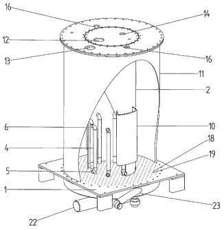
Referring to Figs. 1-3, an embodiment of an apparatus according to the present
invention comprises a central combustion chamber 1 surrounded by an annular
fluidized bed pyrolysis reactor 2. The combustion chamber 1 preferably
comprises a
fluidized bed and is designed to accommodate a second inert fluidizable media
3. A
plurality of lift tubes 4 are provided within the combustion chamber 1, each
having a
lower inlet 5 and an upper outlet 6 located in the pyroiysis reactor 2. Each
lift tube 4
includes a nozzle 7 proximal the inlet 5 for educting a first inert
fluidizable media 8
located within the pyrolysis reactor 2 upwardly through the lift tube 4. The
outlet 6 of
each tube 4 is located within a freeboard area 9 of the reactor 2 when the
fluidized bed
is in operation. A pair of directional devices, each comprising a vertical
duct 10, is
provided within the pyrolysis reactor 2 on the common wall 11 shared with the
combustion chamber 1. Other embodiments of directional devices (eg: elbows,
deflector plates, etc.) may be provided on the outlet 6 of other lift tubes 4
to promote
tangential or radial mixing within the bed. A flue gas outlet 12 is provided
at the top of
the combustion chamber 1 and a product gas outlet 13 is provided at the top of
the
7
CA 02609396 2007-11-23
WO 2006/130977 PCT/CA2006/000933
pyrolysis reactor 2. A fuel inlet opening 14 is provided at the top of the
combustion
chamber 1 that is used to provide a solid fuel 15 (eg: wood, coal, combustibie
biomass,
etc.) and/or recycled char 26 to the combustion chamber. Two biomass inlet
ports 16
are provided in the top of the pyrolysis reactor 1 for admitting biomass 17
through a
suitable airlock means into the reactor 2. The biomass inlet ports 16 may be
connected
into the top of the vertical ducts 10 in order to inject the newly added
biomass 17 within
the bed in a manner as will be more thoroughly described hereinafter.
A distributor plate 18 is provided at the bottom of both the combustion
chamber 1
and the pyrolysis reactor 2. The distributor plate 18 comprises a plurality of
spaced
apart holes 19, the diameter and spacing of which are selected in accordance
with
known design techniques. Apertures 51 are also included for allowing the lift
tubes 4 to
pass through the distributor plate 18. Each hole 19 may include means to
prevent
plugging of the holes upon cessation of upward gas flow through the holes.
This may
comprise a tee-shaped fitting 52 mounted to each of the holes 19 or a conical
shaped
hat spaced above the holes using suitable standoffs. The conical shaped hat
may
include an aperture at the apex thereof allowing the hat to function as a
nozzle and
promoting attrition of the first inert fluidizable media; this advantageously
reduces
accumulation of char 26 on the media and preserves its particle size and
fluidization
characteristics. In the embodiment shown, the distributor plate 18 is
continuous
throughout the pyrolysis reactor 2 and the combustion chamber 1, allowing the
distributor plate to serve as the base for mechanical construction of both
parts of the
vessel. The portion of the distributor plate 18 within the pyrolysis reactor 2
may be flat
or frustoconical in shape to promote the inward and downward movement of media
8
towards the inlet 5 of the lift tubes 4. Of course, the gas flows to the inner
and annular
portions of the vessel are kept separate by means of separate distribution
chambers
20, 21 beneath the plate 18.
One or more air inlets 22 are provided to admit air 27 into the combustion
chamber beneath the plate 18. The flow through the air inlets 22 is controlled
in order
to attain the desired superficiai gas velocity for fluidization of the second
inert fluidizable
media 3. At least one of the air inlets 22 provides air 27 to the vessel that
is heated by
a burner (not shown), preferably burning gaseous or liquid fuel, located in-
line with the
air inlet. The burner is used to pre-heat the vessel during start-up and/or to
provide
8
CA 02609396 2007-11-23
WO 2006/130977 PCT/CA2006/000933
supplementary heat generation during operation. With most sources of biomass
17,
once the air has been pre-heated the char 26 produced during pyrolysis in the
reactor 2
has sufficient residual heat value that a portion of the char can be separated
from the
product gas 33 and re-introduced into the combustion chamber 1 as the sole
source of
fuel needed to maintain process temperature. In other instances, supplementary
solid
fuel 15 may need to be added, either as an alternative or in addition to the
char 26.
The combustion chamber 1 may optionally include one or more internal burners
(not shown) for the combustion of gaseous or liquid fuel. The internal
burner(s) may be
used to pre-heat the vessel in advance of combustion of solid fuel 15 and/or
char 26, to
provide supplementary heat generation during operation, or to provide primary
heat
generation. The burner(s) may be located above or beneath the distribution
plate 18
and connections may be provided on the vessel exterior to admit air and/or
fuel to the
burner.
Solid fuel 15 and/or char 26 entering through the fuel inlet 14 is preferably
provided in a chopped or pulverized form and introduced into the fluidized bed
in the
combustion chamber 1, where auto-ignition takes place due to high temperature
in the
presence of excess air 27. The flue gas 47 contains ash 56 that is removed
therefrom
prior to discharge. Regardless of the source of heating fuel, the pyrolysis
reactor 2 is
preferably operated at a temperature in excess of 350 C, more preferably from
400 to
900 C, yet more preferably from 450 to 800 C, even more preferably from 500
to 700
C. The combustion chamber 1 is operated at a temperature greater than the
pyrolysis
reactor 2 and heat transfer takes place through the common annular wall 11 and
through the lift tubes 4.
In operation, the pyrolysis reactor 2 receives a flow of low oxygen content
gas
(anoxic gas) 28 through an anoxic gas inlet port 23. The low oxygen content
gas 28
may comprise nitrogen present as nitrogen gas (N2), nitrogen oxides (NOx) or
other
forms of reduced nitrogen. In a preferred embodiment, the low oxygen content
gas
comprises the emissions of a diesel engine, for example a diesel engine
connected to
an electric generator used to power other pieces of process equipment when the
apparatus is provided on a trailer as part of a mobile system. Since most
diesel
engines operate at near stoichiometric air/fuel ratios, the engine exhaust
emissions
contain very little free oxygen and comprise mainly carbon oxides (COx),
nitrogen
9
CA 02609396 2007-11-23
WO 2006/130977 PCT/CA2006/000933
oxides (NOx), sulfur oxides (SOx), water, some unburned hydrocarbons and
particulate
matter (soot). Most modern diesel fuels are clean burning and require little
or no
treatment prior to being introduced to the pyrolysis reactor 2; however,
depending upon
the fuel source being used, the diesel exhaust stream may require particulate
removal
and/or SOx scrubbing as pre-treatments.
The low oxygen content gas 28 enters the distribution chamber 21 beneath the
pyrolysis reactor 2 through the anoxic gas inlet port 23 and passes upwardly
through
the distributor plate 18. The reactor 2 contains a first inert fluidizable
media 8, for
example glass beads or silica sand having a Sauter mean particle diameter in
the range
of from 0.05 to 1.0 mm, preferably from 0.07 to 0.30 mm. The superficial
velocity of the
low oxygen content gas 28 is selected to create a uniformly fluidized bed
without bubble
formation. In order to reduce energy cost, it is desirable that the
fluidization gas
flowrate is kept to a minimum; however, it is also important that the flowrate
is sufficient
to promote radial or three-dimensional mixing of solids in order to provide
heat transfer
from the common wall throughout the reactor. Although the biomass 17 typically
has a
much lower density than the first inert fluidizable media 8, the particle size
is greater
and the biomass does not segregate but rather mixes intimately throughout the
bed.
Upon fluidization, the bed expands within the reactor 2 until an upper surface
is
established. The area of the reactor 2 above this upper surface is the
freeboard area 9
of the reactor. The outlet 6 of each lift tube 4 is located in the freeboard
area 9 and the
inlet 5 is at the bottom of the bed. As the inert fiuidizable media 8 and
entrained
biomass 17 exits the tubes 4, it rains down through the freeboard 9 upon the
upper
surface of the bed. This helps to keep light weight biomass 17 or fines from
escaping
into the freeboard 9 and being lost through the product gas outlet 13. A
directional
device may be employed at the outlet 6 to direct the media to a pre-determined
position
within the reactor 2, for example a radial or tangential position relative to
the outlet.
This helps to establish a desirable three-dimensional flow profile in the
reactor 2
wherein the media 8 moves vertically, radially and/or tangentially within the
bed. Use of
a frustoconical distributor plate 18 also helps to create a three-dimensional
media flow
profile by moving the media inwardly as well as downwardly. Since a
significant portion
of the heat transferred to the pyrolysis reactor 2 comes through the common
wall 11
CA 02609396 2007-11-23
WO 2006/130977 PCT/CA2006/000933
shared with the combustion chamber 1, this three-dimensional media flow
profile is
useful in transferring heat throughout the reactor.
In the embodiment shown, two vertical ducts 10 are provided. The ducts 10 are
situated such that the outlet 6 of a lift tube 4 is located within each duct.
Each duct 10
has a top 24 located above the outlet 6 of the lift tube 4 and a bottom
opening 25
located above the inlet 5 of the lift tube. When the fluidized bed pyrolysis
reactor 2 is in
operation, the top 24 is within the freeboard area 9 of the reactor, whereas
the bottom
opening 25 is located within the fluidized bed. As the first inert fluidizable
media 8 and
entrained biomass 17 exit the lift tube 4 through the outlet 6, they are
deposited within
the duct 10 and move downwardly along the common wall 11 to join the bed
through
the bottom opening 25. Biomass 17 being added to the pyrolysis reactor 2 may
be
introduced through the top 24 of the duct 10 and entrained with the downwardly
moving
media 8 in the duct. Intimate contact with the common wall 11 while in the
duct 10
promotes rapid heating of the new biomass 17, and introduction of the biomass
to the
interior of the bed allows it to be mixed immediately with the bed contents,
thereby
reducing the likelihood of segregation and/or freeboard escape. This
advantageously
improves the biomass conversion rate and thereby allows a more compact reactor
to be
built.
A nozzle 7 is located within each lift tube 4 proximal the inlet 5. The nozzle
7
receives a flow of low oxygen content gas 28 provided from the same source as
for the
pyrolysis reactor 2. Although the density of the bed is relatively constant,
there is a
decreasing gas pressure gradient across the bed from bottom to top. The flow
of gas
through the nozzle 7 creates a low pressure in the lift tube 4 relative to the
bottom of
the bed, which causes the media 8 and entrained biomass 17 to enter the lift
tube;
however, the gas pressure created by the nozzle is higher than at the top of
the bed,
which causes the media and entrained biomass to move upwardly through the
tube.
The design of nozzles for the eduction and pneumatic conveying of solids is
known to
persons skilled in the art.
The nozzle 7 may also optionally include means to induce attrition in the
media 8
as an aid in removing any accumulated char 26 therefrom. The attrition
inducing
means (not shown) may include a nozzle insert or an impingement device placed
in
proximity to the nozzle opening. The lift tube 4 may optionally include
attrition inducing
11
CA 02609396 2007-11-23
WO 2006/130977 PCT/CA2006/000933
features. In addition to the removal of char 26, the attrition inducing means
is useful in
reducing the particle size of the biomass 17, particularly in the case of
large biomass
particles that have a tendency to settle in the reactor 2 and are directed to
the lift tube
inlet 5 by the solid flow pattern in the bed and/or the frustoconical
distributor plate 18.
Although the lift tubes 4 are depicted as being straight, in an alternative
embodiment
they may be helical to increase residence time and heat transfer surface area
within the
combustion chamber 1.
The combustion chamber 1 contains a second inert fluidizable media 3. In a
preferred embodiment, the second inert fluidizable media 3 is identical to the
first inert
fluidizable media 8; however, particle size and/or choice of material may be
selected
based upon desired fluidization conditions in the combustion chamber 1 or the
fuel
source being used. Preferably, the second inert fluidizable media 3 has a
Sauter mean
particle diameter in the range of from 0.05 to 1.0 mm, preferably from 0.07 to
0.30 mm.
The superficial velocity in the combustion chamber 1 is selected to provide
uniformly
fiuidized non-bubbling flow in the combustion chamber. The second inert
fluidizable
media 3 is in intimate contact with the common wail 11 and with the lift tubes
4. This
promotes efficient heat transfer to the pyrolysis reactor 2. The media 8 and
biomass 17
that is conveyed through the lift tubes 4 is exposed to the eievated
temperature of the
fluid bed in the combustion chamber 1. Additional reaction takes place during
transport
of material through the lift tubes 4, thereby increasing the reaction rate to
a level greater
than either the reactor alone or a typical shallow fluid bed could produce.
The combustion chamber I may include internal features, such as baffles (not
shown), that promote a radial flow pattern in the bed as an aid in ensuring
that hot
media 3 is constantly being moved to the outside of the bed. The design of the
distributor plate 18 may also incorporate features for creating this radial
media flow.
The height of the fluidized bed in the combustion chamber 1 may be greater
than that of
the bed in the pyrolysis reactor 2, so that even the elbow portion of the lift
tube 4
proximal the outlet 6 may be utilized for heat transfer.
The particle size of biomass feed material 17 is an important parameter in
determining the efficacy of pyrolysis. The amount of energy and effort which
much be
expended to pre-process feed material increases as particle size is reduced.
Typical
particle size for existing fast pyrolysis systems is less than 3 mm in
diameter. Larger
12
CA 02609396 2007-11-23
WO 2006/130977 PCT/CA2006/000933
sized particles are more difficult to agitate and process in the fluid bed, as
they tend to
"sink" to the bottom of the bed where heat transfer, ablation and speed of
thermal
processing are reduced. This has a negative effect on the efficiency of
production of
bio-oil, which is increased when particle processing time is reduced. The
circulation of
reactor media in this invention via the vertical tubes 4 makes it possible for
particles
greater than 3 mm in diameter to remain as part of the bed, rather than simply
residing
on the bottom. This is particularly true when an inclined frustoconical
distributor plate
18 is used, as large particles tend to slide on the plate to the inlet 5 of
one of the lift
tubes 4 and are circulated from the bottom of the fluid bed upwardly to the
top. This
increases overall heat transfer and hastens the processing of these larger
particles.
The ability of this combined vessel to process larger feed material particle
sizes
reduces the amount of ancillary equipment and energy required for pre-
processing and
sizing of biomass feed material, which is advantageous in creating a compact
mobile
processing system.
Referring to Figs. 4 and 5, in a process according to the present invention,
low
oxygen content gas 28 produced as exhaust emissions from a diesel engine 29
powering an electric generator are passed through a filter 30 to remove
particulate
matter and then compressed using a blower 31 prior to introduction to the
distribution
chamber 20 (not shown in Fig. 4) of the pyrolysis reactor 2 through the anoxic
gas inlet
23 (not shown in Fig. 4). A portion of this stream 28 is also provided to the
nozzles 7
via blower 32. Product gas 33 exiting the gas outlet 13 of the pyrolysis
reactor 2 is first
passed through a primary cyclone 34 and then through a secondary cyclone 35 to
remove any particulate matter therefrom. Particulate matter may include
unconverted
biomass 17 and/or char 26. Depending upon the biomass source, the char 26 may
contain significant quantities of inorganic materials such as phosphorus that
are useful,
for example, in the making of fertilizer. The particulate matter removed in
the cyclones
is therefore collected in a bin 36, with a portion of the material collected
in the primary
cyclone 34 being re-introduced into the combustion chamber 1 through a screw
conveyor 37 to serve as a fuel source. The product gas stream 33 may
optionally pass
through a heat exchanger to pre-heat the incoming low oxygen content gas 28
and/or
combustion air 27 being introduced to the apparatus; this heat exchange may
take
place in one or more stages. The product gas next passes through a spray
condenser
38 in order to remove a condensable liquid product 39 therefrom. Once
condensed, the
13
CA 02609396 2007-11-23
WO 2006/130977 PCT/CA2006/000933
liquid is pumped through a fan-radiator type heat exchanger 40 and re-
introduced into
the spray condenser 38 through a spray header to serve as a coolant in
condensing out
additional liquid product. Other types of heat exchangers may be used. Excess
liquid
product is accumulated in an oil reservoir 41. In one embodiment, the
condensable
liquid product 39 may comprise a bio-oil having a useful fuel value; however,
depending
upon the biomass feedstock used, the condensable product may comprise
compositions useful as flavour enhancers or pharmaceutical compounds. After
collection, the condensed liquid product 39 may optionally be sent to
downstream
purification operations (not shown). The cooled and condensed product gas
stream 33
exits the spray condenser 38 into a gas flare 42 in order to burn off any un-
condensed
flammable product as an emission control measure. Alternatively, the cooled
and
condensed product gas stream 33 may be directed to the furnace 1 along with
the
combustion air 27 via bypass valve 55 in order to utilize the heat value of
any non-
condensed combustible products.
Prior to introduction to the reactor 2, biomass 17 is dried, if necessary, to
a
moisture content of 10% or less and then chopped or ground to a size of
approximately
3 mm using grinder 43. The biomass 17 may be optionally screened in order that
the
correct size range is provided. The dried and sized biomass 17 is stored in a
hopper 44
and fed to the pyrolysis reactor 2 through an airlocked rotary solids feeder
45. The
rotary solids feeder 45 comprises a screw conveyor with a substantially sealed
auger
mechanism to reduce or prevent the ingress of air along with the biomass 17.
Alternatively, the biomass 17 may be purged with substantially oxygen free gas
(for
example, the low oxygen content gas 28) prior to introduction to the reactor
2. The
biomass 17 enters one of two vertical ducts 10 (not shown in Fig. 4) within
the pyrolysis
reactor 2 for injection into the fluidized bed.
Combustion air 27 is compressed using a blower 46 and optionally filtered
before
being introduced to the combustion chamber I through the air inlet 22 (not
shown in
Fig. 4). Char 26 removed from the product gas stream 33 by the primary cyclone
34 is
provided to the combustion chamber 1 and mixed with the air 27 in the
fluidized bed,
where auto-ignition takes place due to the high ambient temperatures in the
combustion
chamber. To pre-heat the combustion chamber 1 on startup, an in-line burner 53
is
provided having a gaseous fuel source 54 (eg: natural gas, propane, etc.). The
in-line
14
CA 02609396 2007-11-23
WO 2006/130977 PCT/CA2006/000933
burner 53 could alternatively be provided within the combustion chamber 1.
Flue gases
47 exiting the combustion chamber 1 through the flue gas outlet 12 (not shown
in Fig.
4) are passed through a flue gas cyclone 48 and the hot ash collected
therefrom is
accumulated in a suitable receptacle 49. The ash collected in receptacle 49
may have
commercial value, for example as a concrete additive or other building
material.
Attrition inducing means (for example, nozzles) may be utilized in the
combustion
chamber I to prevent accumulation of ash on the second inert fluidizable media
3. The
hot flue gases may be optionally directed through a flue gas heat exchanger
(not
shown) that is used to pre-heat the incoming air stream 27 and/or the low
oxygen
content gas stream 28. Optional flue gas treatnient, for example using a
catalytic
converter, a filter, and/or a scrubber, takes place prior to discharge of the
flue gas
through the flare 42.
Referring specifically to Fig. 5, the apparatus of the present invention may
be
mounted on a trailer 50 along with the various components described above in
order to
create a mobile processing system. Only some of the process components
depicted in
Fig. 4 are visible in Fig. 5, and still others have been omitted for clarity.
The apparatus
of the present invention is particularly well suited to mobile operation due
to its compact
size, ease of operation, and robustness in terms of feed material pre-
treatment.
The foregoing describes preferred embodiments of the invention and is not to
be
construed in a limiting sense. Variants or mechanical equivalents to the way
in which
the invention works will be apparent to those skilled in the art, along with
further
features and sub-combinations, and are intended to be encompassed by the
following
claims.