Note: Descriptions are shown in the official language in which they were submitted.
w0 9610454'7 FGTIUS95109492
1
' APPARATUS AND METIiOD FOR PERFORMING MICR03~'T.T1>p1C
MANIPULATIONS FOR CI~CAL ANALYSIS AND SYNTFIE51S
S
This itmntion was made with Government support under contract
DE-ACOS-840821400 awarded by the U.S. Department of Energy to Martin Marietta
Energy Systems, Inc. and the Government has certain rights in this imendon.
Field of t a inve tion
The present invention relates generally to miniature instrumentation for
chemical analysis, chemical sensing and synthesis and, more specifiutfly, to
electrieafly
controlled manipulations of fluids in micromachincd channels. These
manipulations can
be used in a variety of applications, including the electrically controlled
manipulation of
IS fluid for capillary electrophoresis, liquid chromatography, flow injection
analysis, and
chetn'scal reaction and synthesis.
Eac o~nd of the invention
Laboratory analysis is a cumbersome process. Acquisition of chemical
and biochemical information requires expensive equipment, specialized labs and
highly
trained persottncI. Pot this reason, laboratory testing is done in only a
fraction of
circumstances where acquisition of chemical information would be useful. A
large
proportion of tesPmg in both research and clinical situations is done with
crude manual
methods that are characterized by high labor costs, high reagent consumption,
long
ZS turnaround times, relative imprec'ssion and poor reproducibility. The
practice of
techniques such as electrophoresis that are in widespread use in biology and
medical
laboratories have not changed significantly in thirty years.
Operations that are performed in typical laboratory processes include
specimen preparation, chemicallbiochemicat conversions, sample fractionation,
signal
detection and data processing. To accomplish these tasks, liquids are often
measured
and dispensed with volumetric accuracy, mixed together, and subjected to one
or several
different physical or chemical environments that accomplish conversion or
fractionation.
In research, diagnostic, or development situations, these opcmtiens are earned
out on a
macroscopic scale using fluid volumes in the range of a few microlirers to
several liters
at a time. Individual operations are performed in series, often using
di$'erent specialized
equipment and instruments for scpartte steps in the nracess. Complications,
difficulty
wo 96ioasa~
PCTfUS95109492
2190429 Z i
and expense arc often the result of operations involving multiple laboratory
processing
steps.
Many workers have attempted to solve these problems by creating
integrated laboratory systems. Conventional robotic devices have been adapted
to
perform pipetting, specimen handling, solution mbdrtg, as well as some
fractionation and
detection operations. However, these devices arc highly complicated, very
expensive
and their operation requires so much training that their use has been
restricted to a
reiatrnly small number of research and development programs. Mo-e successful
have
been automated clinical diagnostic systems for rapidly end inexpensively
performing a
IO small number of appficatians such as clinical chemistry tests for blood
levels of glucose,
electrolytes and gases. Unfortunately due to their complexity, large size and
great cost,
such equipment, is limited in its application to a small number of diagnostic
circumstances.
The desirability of exploiting the advantages of imegrated systems in a
broader context of laboratory applications has led to proposals that such
systems be
miniaturized. In the 1980's, considerable research and development effort was
put into
an exploration of the concept of biosensors with the hope they might fill the
need. Such
devices make use of selective chemical systems or biomolecules that are
coupled to new
methods of detection such as electrochemistry and optics to transduce chemical
signals
to electrical ones that can be interpreted by computers and other signal
processing units.
Unfortunately, biosensors have been a commercial disappointment. Fewer than 20
commercialized products were available in 1993, ac~unting for revenues in the
U.S, of
less thaw 3100 million. Most observers agree that this failure is primarily
technological
rather than reAecting a misinterpretation of market potential. In fav, many
situations
such as massive screening for new drugs, highly parallel genetic research and
testing,
micro-chemistry to minimize costly reagent consumption and waste generation,
and
bedside or doctor's office diagnostics would greatly benefit from miniature
integrated
laboratory systems.
In the early I990's, people began to discuss the possibility of creating
miniature versions of conventional technology. Andrews Manz was one of the
first to
articulate the idea in the scientific pass. Calling them "miniaturized total
analysis
systems,° or "u-TAS," he predicted that it would be possible to
integrate into single
units microscopic versions of the various elements necessary to process
chemical or
biochemical samples, thereby achieving automated experimentation. Since that
time,
miniature components have appeared, particularly molecular separation methods
and
microvalves. However, attempts to combine these systems into completely
integrated
WO 96/04547 3 219 6 4 2 9 P~T~S95109492
~a
systems have not met with success. This is primarily because precisa
manipulation of
tury 9uid volumes in extremely narrow channels has proven to be a ditliwh
technological
hurdle.
One prominent field suscepfble to niuriadrrization is capillary
electrophoresis. Capillary electrophoresis has become a popular technique for
separating
charged molecular species in solution. The technique is performed in small
capillary
tubes to reduce band broadening effects due to thermal comreccion and hence
improve
resolving power. The small tubes imply that minute volumes of materials, an
the order
of nanoliters, must be handled to inject the sample into the separation
capglary tube.
Current techniques for injection include electromigration and siphoning of
sample from a container into a continuous separation tube. Both of these
techniques
suffer from relatively poor reproducibility, end etectromigration additionally
suffers from
electrophoretic mobility-based bias. For both sampling techniques the input
end of the
analysis capillary tube must be transfemd from a buffer reservoir to a
reservoir holding
IS the sample. Thus, a mechanical manipulation is involved. For the siphoning
injection,
the sample reservoir is raised above the buffer reservoir holding the exit end
of the
capillary for a fixed length of time.
l',rt electromigration injection is effected by applying an appropriately
polarized electrical potential across the capillary tube for a given duration
while the
entrance end of the capillary is in the sample reservoir. This can lead to
sampling bias
because a disproportionately larger quantity of the species with hig'rer
electrophoretic
mobr3ities migrate into the tube. The capillary is removed from the sample
reservoir and
replaced into the entrance buffer reservoir after the injection duration for
both
techniques.
A continuing need e>osts for methods and apparatr.ses which lead to
improved electrophoretic resolution and improved injection stability.
umm of the Invention
The present invention provides microchip laboratory systems and
methods that allow comptex biochemical and chemical procedures to be conducted
on a
microchip under electronic control. The microchip laboratory systems comprises
a
material handling apparatus that transports materials through a system of
itrterconnected,
integrated channels on a microchip. The movement of the materials is precisely
dir~tcd
by controlling the electric fields produced in the integrated channels. The
precise control
of the movement of such materials enables precise mixing, separation, and
reaction as
seeded to implement a desired biochemical or chemical procedure.
WO 96/04547
PCTlUS95109492
-2196429
The microchip laboratory system of the present invention analyzes and/or
synthesizes chemical materials in a precise and reproducible manr:er. The
aystem
includes a body having integrated chtumels connecting a plurality of rexrvoirs
that store
the chemical materials used in the chemical analysis or synthesis performed by
the
S system. In one aspect, at least five of the reservoirs simultaneously have a
controlled
alectrical potential, such that material firm at least one of the reservoirs
is transported
through the channels toward at least one of the other reservoirs. The
transportation of
the material through the channels provides exposure to one or more relaxed
chemical or
physical environments, thereby resulting in the synthesis or analysis of the
chemical
material.
The microchip laboratory system preferably also includes one or more
intersections of integrated channels connecting three or more of the
reservoirs. The
laboratory system controls the electric fields produced in the channels in a
manner that
controls which materials in the reservoirs are transported through the
intesaection(s). In
one embodiment, the microchip laboratory system acts as a mixm or diluter that
combines materials in the intersections) by produang an electrical potential
in the
intersection that is less than the electrical potential at each of the two
reservoirs finm
which the materials to be mixed originate. Alternatively, the laboratory
system can act
as a dispenser that electrokinetically injects precise, controlled amounts of
material
through the interscetion(s).
By simultaneously applying an electrical potential at each of at least five
reservoirs, the microchip laboratory system can act as a complete system for
performing
an entire chemical analysis or synthesis. The five or more reservoirs can be
configured in
a manner that enables the elcctrokinetic separation of a sample to be analyzed
("the
analyte") which is then mixed with n reagent from a reagent reservoir.
Alternatively, a
chemical reaction of an analyze and a solvent can be performed firxt, and then
the
material resuItmg from the reaction can be electrokinctically separated. As
such, the use
of five or.more reservoirs provides an integrated laboratory system that can
perform
virtually any chemical analysis or synthesis.
In yet another aspect of the invention, the microchip laboratory system
includes a double intersection formed by channels interconnceting at least six
reservoirs.
The first intersection can be used to inject a precisely sized analyte plug
into a separation
channel toward a waste reservoir. The electrical potential at the second
intersection can
be selected in a manner that provides additional control over the size of the
analyze plug.
In addition, the electrical potentials can be controlled in a manner that
transports
materials from the fifth and sixth reservoirs through the second intersection
toward the
WO 96104547
219 6 4 2 9 P~~S95109492
ww
first intersection and toward the fourth reservoir after a selected wlurie of
material from
the first intersection is transported through the second intersection toward
the fourth
reservoir. Such control can be used to push the analyse plug further down the
separation
Channel while enabling a second anatyte plug to be injected through die first
intersection.
1n another aspect, the microchip laboratory system acts as a microchip
flow control system to control the flow of material through an intersaxion
formed by
integrated channels connecting at least four reservoirs. The micrvchip Bow
control
system simultaneously applies a controlled electrical potential to at least
three of the
reservoirs such that the volume of material uansported from the first
reservoir to a
second reservoir through the intersection is selectively controlled solely by
the
movement of a material from a third reservoir through the intersection.
Preferably, the
material raoved through the third reservoir to selectively control the
material transported
from the first reservoir is directed toward the same second reservoir r~s the
material from
the first reservoir. As such, the microchip flow control system acts as a
valve ora gate
that selective[y controls the volume of material transported through the
intersection.
The microchip flow control system can also be configured to act as a dispenser
that
prevents the first material from moving through the intersection toward the
second
reservoir after a selected volume of the first material has passed through the
intersection.
Alternatively, t1u microchip flow control system can be configured to act as a
diluter
that mares the first and second materials in the intersection in a manner that
simultaneously transports the first and second materials from the intersection
toward the
second reservoir.
Other objects, advantages and salient featwes of the invention will
become apparent from the following detailed description, which taken in
conjunction
with the annexed drawings, discloses preferred embodiments of the invention.
)brief Descriotioa of the Drawingg
Figure I is a schematic view of a preferred embodiment of the present
invention;
Figuro 2 is an enlarged, vertical sectional view of a channel shown;
Figure 3 is a schematic, top view of a microchip according to a second
preferred arrbodiment of the present irrvention;
Figure 4 is an enlarged vices of the intersection region of Figure 3;
Figure 5 are CCD images of a plug,of analyte moving through the
intersection of the Figure 30 embodiment;
CA 02196429 2000-06-07
6
Figure 6 is a schematic top view of a microchip laboratory system according to
a third
preferred embodiment of a microchip according to the present invention;
Figure 7 is a CCD image of "sample loading mode for rhodamine B" (shaded
area);
Figure 8(a) is a schematic view of the intersection area of the microchip of
Figure 6, prior
to analyte injection;
Figure 8(b) is a CCD fluorescence image taken of the same area depicted in
Figure 8(a),
after sample loading in the pinched mode;
Figure 8(c) is a photomicrograph taken of the same area depicted in Figure
8(a), after
sample loading in the floating mode;
Figure 9 shows integrated fluorescence signals for injected volume plotted
versus time for
pinched and floating injections;
Figure 10 is a schematic, top view of a microchip according to a fourth
preferred
embodiment of the present invention;
Figure 11 is an enlarged view of the intersection region of Figure 10;
Figure 12 is a schematic top view of a microchip laboratory system according
to a fifth
preferred embodiment according to the present invention;
Figure 13(a) is a schematic view of a CCD camera view of the intersection area
of the
microchip laboratory system of Figure 12;
Figure 13(b) is a CCD fluorescence image taken of the same area depicted in
Figure 13(a),
after sample loading in the pinched mode;
Figures 13(c)-13(e) are CCD fluorescence images taken of the same area
depicted in
Figure 13(a), sequentially showing a plug of analyte moving away from the
channel intersection at 1, 2
and 3 seconds, respectively, after switching to the run mode;
Figure 14 shows two injection profiles for didansyl-lysine injected for 2s
with y equal to
0.97 and 9.7;
Figure 15 are electropherograms taken at (a) 3.3 cm, (b) 9.9 cm, and (c) 16.5
cm from the
point of injection for rhodamine B (less retained) and sulforhodamine (more
retained);
Figure 16 is a plot of the efficiency data generated from the
electropherograms of Figure
15, showing variation of the plate number with channel length for rhodamine B
(square with plus) and
sulforhodamine (square) with best linear fit (solid lines) for each analyte;
Figure 17(a) is an electropherogram of rhodamine B and fluorescein with a
separation field
strength of 1.5 kV/cm and a separation length of 0.9 mm;
WO 96/04547 219 6 4 2 ~ p~~595109492
E *. ,
Figure 17(b) is an electropherogram of rhodamine B and fluorescein with
a separation field strength of 1.5 kVlcm and a separation length of 1.6 mrn;
Figure 17(c) is an etectropherogram of rhodamine B and fluorescein with
a aepaaation field strength of 1.5 kVlcm and a separafion length of 11.1 mm;
S Figure 18 is a graph showing variation of the number of plates per unit
time as a function of the electric field strength for rhodamine B at
separation lengths of
1.6 mm (circle) and 11.1 mm (square) and for fluorescein at separation
icttgths of L6
mm (diamond) and 11.1 mm (triangle);
Figure 19 shows a chromatogram of coumarins analyzed by
IO eIectrochromatography using the system of Figure 12;
Figure 20 shows a chromatogram of coumarins resulting from micellar
electrokinetic capillary chromatography using the system of Figure I 2;
Figures 21(a) and 21(b) show the separation of tlu~ee metal ions using the
system of Figure 12;
IS Figure 22 is a schematic, top plan view of a microchip according to the
Figure 3 embodiment, additionally including a reagem reservoir and ruction
channel;
Figure 23 is a Schematic view of the embodiment of Figure 20, showing
applied voltages;
Figure 24 shows two electropherograms produced using the Figure 22
20 embodiment;
Figure 23 is a schematic view of a microchip laboraloay system according
to a so<thh preferred embodiment of the present imemion;
Figure 26 shows the reproducibility of the amount injected for arginine
and glycine using the system of Figure 25;
25 Figure Z7 shows the overlay of three electrophorctic separations using
the system ofFigure 25;
Figure 28 shows a plat of amounts injected versus reaction time using the
system ofFigure 25;
1 figure 29 shows an electropherogram of restriction fragments produced
30 using the system of Figure 25;
Figure 30 is a schematic view of a microchip laboratory system according
to a seventh preferred embodiment of the present invention,
Figure 31 is a schematic view of theapparatus of Figuro 21, showing
sequential applications of voltages to effect desired fluidic manipulations;
and
35 Figure 32 is a graph showing the different voltages applied to effect the
fluidic manipulations of Figure Z3.
WO 96/04547 PC'flUS95l09492
2196429
Detailed Taescria~on of the Tnverrtion
Integrated, micro-laboratory systems for uralyzin,4 or synthesuzng
chemicals require a precise way of manipulating fluids and fluid-borne
material and
subjecting the fluids to selected chemical or physical environments that
produce desired
conversions or partitioning. Given the concentration of analytes that produces
chemical
conversion in reasonable time scales, the nature of molecular detectvon,
ditTusion times
and manufacturing methods for creating devices on a microscopic scale,
miniature
integrated micro-laboratory systems lend themselves to channels ha~,vtg
dimensions on
the order of 1 to 100 micrometers in diameter. Within this contact,
electrokinetic
pumping has proven to be versatile and efl'ective in transpcrting materials in
nticrofabricated laboratory systems.
The present invention provides the tools necessary to make use of
electrokinetic pumping not only in separations, but also to perform liquid
handling that
accomplishes other important sample processing steps, such as cherrucal
conversions or
sample partitioning. By simultaneously controlling voltage at a plurality of
ports
canaCCted by channels in a microchip suucture, h is possible to measure and
dispense
fluids with great precision, mix reagents, incubate reaction components,
direct the
components towards sites of physical or biochemical partition, and subject the
components to detector systems. By combining these capabilities nn a single
microchip,
one is able to create complete, miniature, integrated automated laboratory
systems for
analyzing or synthesizing chemicals.
Such integrated micro-laboratory systems can be made up of several
component elements. Component elements can include liquid dispersing systems,
liquid
mixing systems, molecular partition systems, detector sights, etc. For
example, as
descnbed herein, one can construct a relatively complete system for the
identification of
restriction endonuclease sites in a DNA molecule. This single microfabricated
device
thus includes in _a single system the functions that are traditionally
performed by a
technician employing pipettors, incubators, gel electrophoresis systems, and
data
acquisition systems. In this system, DNA is mixed with an enzyme, the mixture
is
incubated, and a selected volume of the reaction mixture is dispensed into a
separation
channel. Electrophoresis is conducted concurrent with fluorescent labeling of
the DNA.
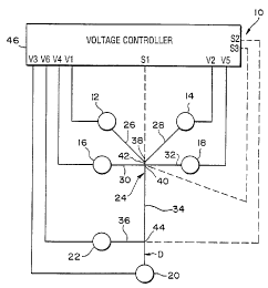
Shown in Figure 1 is an example of a microchip laboratory system 10
configured to implement an entire chemical analysis or synthesis. The
laboratory system
10 includes six reservoirs I2, 14, 16, 18, 20, and 22 connected to ea~~h other
by a system
of channels 24 micromachined into a substrate or base member (not shown in
I:rg. 1), as
,-
WO 96104547 ; ~ (~ ~ ~ pC'ffUS95109492
.. ~,
discussed in more det;sil below. Each reservoir 12-22 is
in fluid communication with a
comespond'mg channel 26, 28, 30, 32, 34, 36, and 38 of
the channel system 24. The first
charmer 26 leading from the first reservoir 12 is connected
to the second channel 28
leading from the second reservoir 14 at a first intersection
38. Likewise, the third
S channel 30 from the third reservoir 16 is connected to
the fourth chsmnel 32 at a second
intersection 40. The first intersection 38 is connected
to the second intersection 40 by a
reaction chamber or channel .42. The fifth chamtel 34 fibm
the fifth reservoir 20 is also
connected to the second intersection 40 such that the second
intersection 40 is a four-
way intersection of channels 30, 32, 34, and 42. The fifth
channel 34 also intersects the
sixth channel 36 firom the sixth reservoir 22 at a third
intersection 44
The materials stored in the .reservoirs preferably are
transported
electrokinctically through the channel system 24 in order
to implement the des'urd
analysis or synthesis. To provide such electrolonetic transport,
the Laboratory system 10
W ncludes a voltage controller 46 capable of applying selectable
volW ge levels, including
ground. Such a voltage controller can be implemented using
multiple voltage dividers
and multiple relays to obtain the selectable voltage leveL~.
The voltage controller is
connected to an electrode positioned in each of the six
reservoirs 1 Z-22 by voltage lines
VI-V6 in order to apply the desired voltages to the materials
in the reservoirs.
Preferably, the voltage controller also includes sensor
channels Sl, S2, and S3 connected
to the 5rst, second, and third intersections 38, 40, 44,
respectively, in order to sense the
voltages present at those intersections.
The use of electrokinenc transport on microminiaturized
planar liquid
phase separation devices, described above, is a viable
approach for sample manipulation
and as a pumping mechanism for liquid chromatography. The
pn;sent imcntion also
entails the use of electroosmotic flow to tithe various
fluids in a controlled and
reprodua~ble fashion_ When an appropriate fluid is placed
in a tube made of a
correspondingly appropriate material, functional groups
at the surface of the tube can
ionize. In the case of tubing materials that are terminated
in hydroxyl groups, protons
will leave the surface and enter an aqueous solvent. Under
such conditions the surfiue
will have a net negative charge and the solvent will have
an excess of positive charges,
mostly in the charged double layer at the surface.With
the application of an electric
field across the tube, the excess canons in solution will
be attractel to the cathode, or
negative electrode. The movement of these positive charges
throuF;h the tube will drag
the solvent with them. The Steady state velocity is given
by equation i,
v=E~~ (1)
4an
CA 02196429 2000-06-07
where v is the solvent velocity, ~ is the dielectric constant of the fluid, ~
is the zeta potential of the
surface, E is the electric field strength, and rl is the solvent viscosity.
From equation 1 it is obvious that
the fluid flow velocity or flow rate can be controlled through the electric
field strength. Thus,
electroosmosis can be used as a programmable pumping mechanism.
5 The laboratory microchip system 10 shown in Figure 1 could be used for
performing
numerous types of laboratory analysis or synthesis, such as DNA sequencing or
analysis,
electrochromatography, micellar electrokinetic capillary chromatography
(MECC), inorganic ion
analysis, and gradient elution liquid chromatography, as discussed in more
detail below. The fifth
channel 34 typically is used for electrophoretic or electrochromatographic
separations and thus may be
10 referred to in certain embodiments as a separation channel or column. The
reaction chamber 42 can
be used to mix any two chemicals stored in the first and second reservoirs 12,
14. For example, DNA
from the first reservoir 12 could be mixed with an enzyme from the second
reservoir 14 in the first
intersection 38 and the mixture could be incubated in the reaction chamber 42.
The incubated mixture
could then be transported through the second intersection 40 into the
separation column 34 for
separation. The sixth reservoir 22 can be used to store a fluorescent label
that is mixed in the third
intersection 44 with the materials separated in the separation column 34. An
appropriate detector (D)
could then be employed to analyze the labeled materials between the third
intersection 44 and the fifth
reservoir 20. By providing for a pre-separation column reaction in the first
intersection 38 and reaction
chamber 42 and a post-separation column reaction in the third intersection 44,
the laboratory system
10 can be used to implement many standard laboratory techniques normally
implemented manually in
a conventional laboratory. In addition, the elements of the laboratory system
10 could be used to build
a more complex system to solve more complex laboratory procedures.
The laboratory microchip system 10 includes a substrate or base member (not
shown
in Fig. 1) which can be an approximately two inch by one inch piece of
microscope slide (Corning, Inc.
#2947). While glass is a preferred material, other similar materials may be
used, such as fused silica,
crystalline quartz, fused quartz, plastics, and silicon (if the surface is
treated sufficiently to alter its
resistivity). Preferably, a non-conductive material such as glass or fused
quartz is used to allow
relatively high electric fields to be applied to electrokinetically transport
materials through channels in
the microchip. Semiconducting materials such as silicon could also be used,
but the electric field
applied would normally need to be kept to a minimum (approximately less than
300
CA 02196429 2000-06-07
11
volts per ccntimctcr using present techniques of providing insulating layers
which .may
provide insufficient electrokinctic movement.
The channel pattern 24 is formed in a planar sueface of the substrate using
standard photolithographic procedures followed by chemical wet aching. The
channel
3 pattern rosy be transferred onto the substrate with a positive photorcaist
(Shipley*I811)
and an e-beam written chrome mask (Institute of Advaaccd Manufacduing
Sciences,
Ins.). The pattern may be chemically etched using HF/N)Ei,F solution
ABer forming the channel pattern, a cover plate may then be bonded to
the substrate using a direct bonding technique whereby the substrate and the
cover plate
10 surfaces are first hydrolyzed in a .dilute NW,OHIH,O= solution and then
joined. The
assembly is then annealed at about 500° C in order to in.~tre proper
adhesion of the
cover plate to the substrate.
Following bonding of the cover plate, the reservoirs are affixed to the
substrate, with portions of the coves plate sandwiched thcrebetweeri, using
epoxy or
15 other suitable means. The reservoirs can be cylindrical with open opposite
axial ends.
Typically, electrical contact is trade by piecing a platinum wire electrode in
each
resetvoirs. 'The electrodes are connected to a voltage controller 46 which
applies a
desired potential to select electmdcs, in a manner described in more detail
blow.
A cross section of the first channel is shown in Ftgwe 2 and is identical to
20 the cross section of each of the other integrated channels. When using a
non-crystalline
material (such as glass) for the substrate, and when the channels are
chemically wet
etched, an isotropic etch ocauS, i.e., the glass etches uniformly in ail
directions, and the
resulting channel geometry is trapezoidal. The trapezoidal cross section is
due to
"undercutting" by the chemical etching process at the edge of the phototesis<.
In one
25 embodiment, the channel cross section of the illustrated embodiment has
dimensions of
5.2 pin in depth, 57 pro in width at the top and 45 pin in widtJs at the
bottom. In
another embodiment, the channel has a depth "d" of i0pcr~ an upper width "wI"
of
901tm, and a lower width "w2" of 70pm.
An important aspect of the present invention is the controlled
30 electrokinetic ttansportation of materials through the channel system 24.
Such
controlled electrokinetic transport can be used to dispense a selected amount
of material
from one of the reservoirs through one or more intersections of the c.hanncl
structure 24.
Alternatively, as noted above, selected amounts of materials from two
rcsec~roirs can be
transported to an imersection where the materials can be mixed in desired
35 concentrations.
* trade-mark
WO 96/0454
PCT/US95109492
2196429 '
rat a 17i n
Shown in Figure 3 is a laboratory component l0A that can be used to
implement a preferred method oftransparting materials through n channel
strucnrre 24A
The A following each number in Figure 3 indicates that it corresponca to nn
analogous
element of Figure 1 of the same number without the A. For simplicity, the
electrodes
and the connections to the voltage controller that controls the transport of
materials
through the channel system 24A are not shown in 1 figure 3.
The microchip laboratory system IOA shown in Figure 3 controls the
amount of material from the first reservoir 12A transported through tFe
intersection 40A
toward the fourth reservoir 20A by electrokinetieally opening and closing
access to the
intersection 40A from the first channel 26A As such, the laboratory microchip
system
IOA essentially imptements s controlled electroldnetic valve. Such an
electrokinetic
valve can be used as a dispenser to dispense selected volumes of a sin~Ic
material ar as a
mixer to mix selected volumes of plural materials in the intersection 40A. In
general,
electro-osmosis is used to transport "fluid materials" and electrophoresis is
used to
transport ions without transporting the fluid material surrounding the ions.
Accordingly,
as used herein, the tam "material" is used broadly to cover any form of
material,
including fluids and ions.
The laboratory system l0A provides a continuous tut:dhectional flow of
fluid through the separation channel 34A. This injection or dispensing scheme
only
requires that the voltage be changed or removed from one (or two) reservoirs
and allows
the fourth reservoir 20A to remain at ground potential. This wrll allow
injection and
separation to be performed with a single polarity power supply.
An enlarged view of the intersection 40A is shoum in 1 figure 4. The
directional arrows indicate the time sequence of the flow profiles at the
intersection 40A.
The solid arrows show the initial flow pattern Voltages at the va-ious
reservoirs are
adjusted to obtain the descn'bed flow patterns. The initial flow pattern
brings a second
material from the sccand reservoir 16A at a sutftcient rate such that all of
the first
material transported from reservoir 12A to the intersection 40A is pushed
toward the
third reservoir 18A. In general, the potential distribution will be such that
the highest
potential is in the second reservoir 16A, a slightly lower potemial in the
first
reservoir 12A, and yet a lower potential in the third reservoir IEA, with the
fourth
reservoir 20A being grounded. Under these conditions, the flaw towards the
fourth
reservoir 20A is solely the second material from the second reservoir ltiA.
To dispense material from the first reservoir 12A through the intersection
40A, the potential at the second reservoir 16A can be switched to a value less
than the
WO 9bI04547 219 6 4 2 9 pCT~S95109492
potential of the first reservoir 12A or the potentials at reservoirs 16A
and/or 18A, can be
floated momentarily to provide the flow shown by the short dashed arrows in
Figure 4.
Under these conditions, the primary flow will be from the first reservoir 12A
down
inwards the separation channel waste reservoir 20A. The flow frnm the second
and
3 third reservoirs 16A, 18A will be small and could be in either direction.
This condition is
held long enough to transport a desired amoum of material from the fast
reservoir 12A
through the intersection 40A and into the separation channel 34A. After
sufficient time
for the desired material to pass through the intersection 40A, the voltage
distribution is
switched back to the origins! values to prevent additional material from the
first reservoir
12A from flowing through the intersection 40A toward the separation channel
34A.
Oae application of such a "gated dispense" is to inject a controlled,
variable-sized plug of analyte from the first reservoir 12A for
electrophoretic or
chromatographic separation in the separation channel 34A. In such a system,
the first
reservoir 12A stores analyte, the second reservoir 16A stores an ionic buffer,
the third
li reservoir 18A is a &rst waste reservoir and the fourth resecveir 20A is a
second waste
reservoir. To inject a small variable plug of analyze from the first reservoir
12A, the
potentials at the buffer and frost waste reservoirs 16A, 18A are simply
floated for a short
period of time (a 100 ms) to allow the analyte to migrate down the separation
column
34A. To break off the injection plug, the potentials at the buffer res~.avoir
16A and the
first waste reservoir 18A are reapplied. Alternatively, the valuing sequence
could be
effected by bringing reservoirs 16A and 18A to the potential of the
inlcrsection 40A and
then retaining them to their original potentials. A shortfall of this method
is that the
composition of the injected plug has an eIectrophoretic mobility bias whereby
the faster
migrating compounds are introduced preferentially into the separation column
34A over
slower migrating compounds.
In Figure 5, a sequential view of a plug of analytc moving through the
intersection of the Fgure 3 embodiment can be seen by CCD images The analyze
being
pumped through the laboratory system l0A was rhodamine B (shaded area), and
the
orientation of the CCD images of the injection cross or intersectior, is the
same as in
Figure 3. The first image, (A), shows the analyte being pumped tbtnugh the
injection
cross or intersection toward the first waste reservoir 18A prior to the
injection. The
second image, (B), shows the analyze plug being injected into the separation
column
34A. The third image, (C), depicts the analyze plug moving away from the
injection
intersection after an injection plug has been completely introduced into the
separation
column 34A, The potentials at the buffer and fast waste reservoirs 16A, 18A
were
floated for 100 ms while the sample moved into the separation column 34A. By
the time
CA 02196429 2000-06-07
14
of the (C) image, the closed gate raode has resumed to stop further analytc
from moving
through the intersection 40A into the separation column 34A, and a clean
injection plug
with a length of 142 Itm has been introduced into the separation column. As
discussed
below, the gated injector contn'butes to only a minor fraction of the total
plate height.
The irrjxtion plug length (volume) is a function of the time of the injection
and the
electric 5eld strength in the column. The shape of the iaj~ plug is skewed
slightly
because of the directionality of the cleaving buffer flow. However, fc~t a
given injection
period, the reproduability of the amount injected, determined by integrating
the peak
area, is 1% RSD for a series of 10 replicate injections.
Electrophoresis experiments were conducted using the microchip
laboratory system l0A of figure 3, and employed methodology according to the
present
invention. Chip dynamics were analyzed using analyte fluorescence. A charge
coupled
device (CCD) camera was used to monitor designated areas of the chip and a
photomultiplier tube (PMT) tracked single point events. The CCD (Princeton
Instruments, Inc. TFJCCD-S 12TIQ~ camera was mounted on a stereo microscope
(Nikon'~'SMZ ~, and the laboratory system l0A was illuminated using an argon
ion laser
(514.5 rim, Coherent Innova 90) operating at 3 W with the beam expanded to a
circular
spot ~ 2 em in diameter. ?he PMT, with collection optics, was situated below
the
microchip with the optical axis perpendicular to the microchip surface. The
laser was
operated at approximately 20 mW, and the beam impinged upon the microchip at a
45°
angle from the microchip surface and parallel to the separation channel. The
laser bcarn
and PMT observation axis were separated by a 135° angle. The poir:t
detection scheme
employed a helium-neon laser (543 nm, PMS Electro-optics LIiGP-0051) with an
electrometer (Keithley617) to monitor response of the PMT (Oricl 77340). The
voltage
controller 46 (Spellman CZE 1000R) for electrophoresis was operated betvrcen 0
and
+4.4 kV relative to ground.
The type of gated injector descnbed with respect to Fi;,'ures 3 and 4 show
electrophoretic mobility based bias as do conventional eleetrcu~smotic
injections-
Nonetheless, this approach has simplicity in voltage switching requirements
and
fabrication and provides continuous unidirectional flow through the separation
channel.
In addition, the gated injector provides a method for valuing a variable
volume of fluid
into the separation channel 34A in a manner that is precisely controlled by
the electrical
potentials applied.
Another application of the gated dispenser l0A is to dilute or mix desired
quantities of materials in a controlled manner. To implement such a mixing
scheme in
order to mix the materials from the first and second reservoirs 12A, 16A, the
potentials
* trade-mark
w0 96/04547 2 1 9 6 4 2 9 p~~S95109492
in the first and second channels 26A, 30A need to be maintained higher than
the
potential of the intersection 40A during moving. Such potcotials wilt cause
the materials
from the first and second reservoirs 12A and 16A to simultaneously move
through the
intersection 40A and thereby mix the two materials. The potentials applied at
the first
i and second reservoirs 12A, I6A can be adjusted as desired to arhieve the
selected
concentration of each material. After dispensing the desired amuun s of each
material,
the potential at the second reservoir 16A may be increased in a manner
sufScient to
prevent further material from the first reservoir 12A from being transported
through the
intersection 40A toward the third reservoir 30A.
Analvte Tnjector
Shown in Figure 6 is a microchip artalyte injector 108 according to the
present irwcn~on. The channel pattern 24B has four distinct channels 26B, 30B,
32B,
and 34B micromachincd into a substrate 49 as discussed above. Each channel has
an
accompanying reservoir mounted above the terminus of etch channel portion, and
all
four channels intersect at one end in a four way intersection 40B. T:u
opposite ends of
each section provide termini that extend just beyond the peripheral edge of a
cover plate
49' mounted on the substrate 49. The anatyte injector LOB shown in Figure 6 is
substantially identical to the gated dispenser LOA except that the electrical
potentials are
applied in a manner that injects a volume of material from reservoir 16%
through the
intersection 40B rather than from the reservoir 12B and the votume of materitd
injected
is controlled by the size ofthe intersection.
The embodiment shown in Figure 6 can be used fir various material
manipulations. In one application, the laboratory system is used to in ect an
analyte from
an snalyte reservoir 16B through the intersection 40B for separation in the
separation
channel 34B. The anatyte injector tOB can be operated in either "load" mode or
a "run"
mode. Reservoir 16B is supplied with an analyte and reservoir 12B with buffer.
Reservoir 18B acts as an analyte waste reservoir, and reservoir 20B acts as a
waste
reservoir.
In the "load" mode, at least two types of analyte introduction arc
possible. In the first, lutown as a "floating" Loading, a potential is applied
to the analyte
reservoir 16B with reservoir 18B grounded. At the same time, reservoirs 12B
and 20B
are floating, meaning that they are neither coupled to the power source, nor
grounded.
The second load mode is "pinched° loading mode, wherein potentials
are
simultaneously applied at reservoirs 12B, 168, and 20B, with reservoir 18B
grounded in
order to control the injection plug shape as discussed in mare detail below.
As used
WO 96/04547 PC'TIUS95l09492
.2_~ 96429
herein, simultaneously controlling electrical potentutls at plural reservous
means that the
electrodes are connected to a operating power source at dte same chemically
significant
time period. Floating a reservoir means disconnecting the electrode m the
reservoir from
the power source and thus the electrical potential a the reservoir is r!ot
corttro3led.
In the "sun" mode, a potcntiat is applied to the buffemeservoir 12B with
reservoir 20B grounded and with reservoirs 16B and 18B at approximately half
of the
potential of reservoir 12B. During the run mode, the relatively high potential
applied to
the buffer reservoir 12B causes the analyte in the itrtersection 40B to move
toward the
waste reservoir 20B in the separation column 34B.
IO Diagnostic experiments were performed using rhodamine B and
sutforhodamine 101 (Exciton Chemical Co., Inc.) as the analyte at GO 1tM for
the CCD
images and 6 pM for the point detection. A sodium tetraborate 6ufiar (50 rnM,
pH 9.2)
was the mobile phase in the experiments. An injection of spatially well
defined small
volume ( x 100 pL) and of small longitudinal extent ( = 100 wm), injection is
beneficial
when performing these types of anaiyscs.
The analyze is loaded into the inje~~tion cross as a frontal
eIectropherogram, sad once the front of the slowest analyze component passes
through
the injection cross or intersection 40B, the analyze is ready to be analyzed.
1n Figure 7, a
CCD image (the area of which is denoted by the broken line square) displays
the flow
pattern of the analyze 54 (shaded area) and the buffer (white area) tlunugh
the region of
the injection intersection 408.
By pinching the flow of the analyze, the volume at the analyze plug is
stable over time. The slight asymmetry of the plug shape is due to the
ddfcrcnt electric
field strengths in the buffer channel 2tB (470 Vlcm) and the sept~ration
channel 34B
(100 V/cm) when 1.0 kV is applied to the buffer, the analyze and tae waste
reservoirs,
and the analyte waste reservoir is grounded. However, the diiF~mt field
strengths do
not influence the stability of tile analyze plug injected. Id~lly, when the
analyte plug is
injected into the separation channel 34B, only the analyrte in the injection
cross or
intersection 40B would migrate into the separation channel.
The volume of the injection plug in the injection cross is approximately
120 pL with a plug Length of 130 ~tm. A portion of the analyze 54 ir. the
analytc channel
30B and the analyte waste channel 32B is drawn into the separation channel
348.
Following the switch to the separation (run) mode, the volume of the injection
plug is
approximately 250 pL with a plug length of 208 ltm. These dimensions arc
estimated
from a series of CCD images taken immediately after the switch is made to the
separation mode.
W O 96104547 219 6 4 2 9 P~~S95109492
17
The two modes of loading were tested for the analyse introduction into
the separation channel 348. The analyte was placed in the analyte reservoir
1GB, and in
both injection schemes was "transported" in the direction of raeivoir 18B, a
waste
reservoir. CCD images of the two types of iryections are depicted in Figures
8(a)-8(c).
figure 8(a) schematically shows the intersection 40B, as well as the end
portions of
channcla.
The CCD image of Figure 8(b) is of loading in the pinched mode, just
prior to being switched to the run mode. In the pinched mode, ana sere (shown
as white
against the dark background) is pumped electrophoreticaity and
eicc?roosmotically from
reservoir 16B to reservoir 18B (left to right) with buffer from the buffer.
reservoir 12B
(top) and the waste reservoir 208 (bottom) traveling toward reservoir 18B
(right). The
voltages applied to reservoirs 12B, 16B, 18B, and 20B were 90~/0,
90°!0, 0, and 100%
respectively, of the power supply output which correspond to electric 5eld
strengths in
the corresponding channek of 400, 270, 690 and 20 V/cm, respectively. Although
the
IS voltage applied to the waste reservoir 20B is higher than voltage a~~plied
to the analytc
reservoir 18B, the additional length of the separation channel 343 compared to
the
analyte channel 308 provides additional electrical resistance, and tines the
flow from the
arialyte buffer 16B into the intersection predominates. Consequenth,~, the
anaiyte in the
injection cross or intersection 40B has a trapemidal shape and is spatially
constricted in
the channel 32B by.this material transport pattern.
Fgure 8(c) shows a floating mode loading. The analyze is pumped from
reservoir 16B to 18B as in the pinched injection except no potential is
applied to
reservoirs 12B and 20B. By not controlling the flow of mobile phase (buffer)
in channel
portions 26H and 34B, the analyze is free to expand into these channels
through
connective and diffusive Bow, thereby resulting in an extended injection plug.
When comparing the p'mched and floating injections, the pinched injection
is superior in three areas: temporal stability of the injected volume, the
precision of the
injected volume, and plug length. When two or more analyzes with vastly
different
mobilities are to be analyzed, an injection with temporal stability insures
that equal
volumes of the faster and slower moving analyzes are introduced into the
separation'
column or channel 34B. The high reproducibility of the injection volume
facilitates the
ability to perform quantitative analysis. A smaller plug length leads to a
higher
separation efflcieacy and, consequently, to a greater component capacity for a
given
instrument and to higher speed separations-
To determine the temporal stability of etch mode, a series of CCD
fluorescence images were collected at 1.5 second intervals starting just prior
to the
W0 96/04547 , PCTlUS95109492
2 i 96429 ,a
analyze reaching the injection intersection 40B. M estimate of tlca amount of
analyte
that is injected was determined by integrating the fluorescence in the
intersection 408
and channels 26B and 34B. This fluorescence is plotted vec~s timr in Figure 9.
For the pinched injection, the injected volume stabil;xes in a few seconds
and has a stability of 1% relative standard deviation (RSD), which is
comparable to the
stability of the r7luminating laser. For the floating injection, the amount of
utalyte to be
injected into the separation channel 34B increases with time becatae of the
dispersive
flow of analyze into channels 26B and 34B. For a 30 second injection, the
volume of the
injection plug is. ca. 90 pL and stable for the pinched inj~tion versus ca.
300 pL and
contirmously increasing with time for a floating injection.
By monitoring the separation channel at a point 0.9 cm From the
intersection 408, the reproducibility for the pinched injection rr ode was
tested by
integrating the area of the band profile following introduction into the
separation channel
34B. For six injections with a duration of40 seconds, the reproducibility for
the pinched
injection is 0.7°/ fZSD. Most of this measured instability ~s from the
optical
measurement system. The pinched injection has a higher reproducibility because
of the
temporal stability of the volume injected. With electronically controlled
voltage
switching, the RSD is expected to improve for both schemes.
The injection plug width and, ultimately, the resolution between analyzes
depends largely on both the flow pattcm of the analyte and the dimensions of
the
injection cross or intersection 40B. For this column, the width of the channel
at the top
is 90 prr~ but a channel width of 10 ~tm is feasible which would Lead to a
decrease in the
volume of the injection plug from 90 pL down to 1 pL with a pinchecf
injection.
There are situations where it may not be desirable to reverse the flow in
the separation channel as described above for the "pinched" and "floating"
injection
schemes. F.xamplcs of such cases might be the injection of a new sample plug
before the
preceding plug has been completely eluted or the use of a post-column reactor
where
reagent is continuously being injected into the end oftlre separation column.
In the latter
case, it would in general not be dcsirable.to have the reagent flowiag back up
into the
separation channel.
Alternate An~~or
Figure 10 illustrates an alternate analyte injector sys~.em IOC having six
different ports or channels 26C, 30C, 32C, 34C, 56, and 58 respectivoly
connected to six
different reservoirs 12C, 16C, 18C, 20C, 60, and 62. The letter C after each
element
number indicates that the indicated element is analogous to a correspondingly
numbered
WO 96104547 1 9 2 i 9 6 4 2 9 P~~S95I09492
elements of Figure 1. The microchip laboratory system lOC is sirnilar to
laboratory
systems 10, 10A, and lOB described previously, in that an injection cross or
intersection
40C. is provided. In the Figure 10 embodiman, a second intersection 64 and two
additional reservoirs 60 and 62 arc also provided to overcome the problems
with
reversing the flow in the sepatxtion channel
Ltice the previous embodiments, the analyze injector system IOC can be
used to implement an analyze separation by decxrophorasis or chromatography or
dispense material into some other processing element. 1n the laboratory system
IOC, the
reservoir 12C contains separating buffer, reservoir 16C contains the analyze,
and
reservoirs 18C and 20C are waste .reservoirs. Intersection 4oC prefe xbly is
operated in
the pinched mode as in the embodiment shown in Figure 5. The lower
intersection 64, in
fluid communication with reservoirs 50 and 62, are used to provide additional
flow so
that a continuous buffer stream can be directed down towards the ~ rite
reservoir 20C
and, when needed, upwards toward the injection intersection 40C. Reservoir 60
and
attached channel 56 are not necessary, although they improve performance by
reducing
band broadening as a plug passes the lower intersection 64. In many cases, the
flow
from reservoir 60 will be symmetric whh that from resenroir 62.
lagure 11 is an enlarged view of the two intersections 40C and 64. The
different types of arrows show the flow directions at given instances in tune
for injection
of a plug of analyze imo the separation channel. The solid arrows show the
initiat flow
pattern where the analyte is elcetrokinetically pumped into the upper
interaec.~tion 40C
and "pinched" by material flow from reservoirs 12C, 60, and 62 toward this
same
intersection. Flow away from the injection intersection 40C is carried to the
anaiyte
waste reservoir I8C. The analyte is also flowing from the reservoir 16C to the
analyze
waste reservoir 18C. Under these conditions, flow from reservoir 50 (and rest-
rvoir 6Z)
is also going down the separation channel 34C to the waste reservoir 20C. Such
a flow
pattern is created by simultaneously controlling the electrical potentials at
all six
iCSeNOttS.
A plug of the analyze is injected through the inject~on intersection 40C
into the separation channel 34C by switching to the flow profile shown by the
short
dashed arcows. Buffer flows down from reservoir I2C to the injection
intersection 40C
and towards reservoirs 16C, 18C, and 20C. This flow profile also pushes the
analytc
plug toward waste reservoir 20C into the separation channel 34C as described
before.
This flaw profile is held for a sufficient length of time so as to move the
analyze plug past
the lower intersection 64. The flow of buffer from reservoirs 60 and b2 should
be low as
indicated by the short arrow and into the separation channel 34C to minimize
distortion.
WO 96/04547
PCT/US95109492
2196429 2°
The distance between the upper and lower irrtersectiuns 40C and 64,
respectively, should be as small as possible to minhnize plug distortion and
criticality of
tuning in the switching between the two flow conditions. Electrodta for
sensing the
electrical potential may also be placed at the tower intersection and is the
channels 56
and 58 to assist in adjusting the electrical potentials for proper flow
control. Accurate
flow control at the lower intersection 64 may be necessary to prevcu undesired
band
broadening.
After the sample plug passes the lower inteaection, the potentials are
switched back to the initial conditions to givo the original flow profile as
shown with the
IO long dashed arrows. This flow pattern will allow buffer Bow into the
separation channel
34C white the next analyte plug is being transported to the plug fonning
region in the
upper intersection 40C. This injection scheme will allow a rapid succession of
injections
to be made and may be very important for samples that are slow to m~grate or
if it takes
a long time to achieve a homogeneous sample at the upper intersection 40C such
as with
entangled polymer solutions. This implementation of the pinched injection also
maintains unidirectional flow through the separation channel as miglu be
required for a
post-column reaction as discussed below with respect to Figr~ra 22.
Se~~emine Channel
Another embodiment of the invemion is the modofiul analyte injector
system lOD shown in Figure 12. The laboratory system 10D shown in Figure 12 is
substantially identical to the laboratory system LOB shown in 1~igura 6,
except that the
separation channel 34D follows a serpentine path. The serpentine path of the
separation
channel 34D allows the length of the separation channel to be greatly
increased without
substantiaiiy increasing the area of the substrate 49D needed to imple:nerrt
the serpentine
path. increasing the Icngih of the separation charmel 34D increases the
ability of the
laboratory system IOD to distinguish elements of an analyte. In one
particularly
preferred embodiment, the enclosed Length (that wtrich is covered by the cover
plate
49D~ of the channels extending from reservoir 16D to reservoir 18D is 19 mm,
while the
length of channel portion 26D is 6.4 mm and channel 34D is 17I mm. The taro
radius of
each turn of the channel 34D, which serves as a separation column, is 0.16 mm.
Ta perform a separation using the modified anatyte u;jector system lOD,
an analyte is first loaded into the injection inters~tion 4oD using one of the
Loading
methods described about. Alter the analyte has been loaded into the
intersection 40D of
the microchip laboratory system 10, the voltages arc manually switched fiom
the loading
mode to the_ run (separation) mode of operation. Figures l3la)-13(e)
illustrate a
WO 96104547 ~ ~ 9 S 4 2 ~ pCTlUS95109492
21
separation of rhodamine B (less retained) and sulforhodamine (more retained)
using the
following conditions: l::u=400 V/cm, E"o= 150 V/cm, bulfi:r= 50 mM sodium
tetraborate at pH 9.2. The CCD images demonstrate the separation process at 1
second
intervals, with Figure 13(a) showing a schematic of the section of the chip
imaged, and
with Figures 13(b)-13(e) showing the separation unfold.
Figure 13(b) again shows the pinched injection with the applied wltages
at reservoirs 12D, 16D, and 20D equal and reservoir 18D groundW. Figures 13(c)-
13(e) shows the plug moving away from the intersection at 1, 2, and 3 seconds,
respectively, after switching to the tun mode. In Figure 13(c), the injection
plug is
migrating around a 90° turn, and band distortion is visible due to the
inner portion of the
plug traveling less distance than the outer portion. By Iagure 13(dl, the
analyzes have
separated into distinct bands, which are distorted in the shape of a
parallelogram. In
Figure 13(e), the bands are well separated and have attainrx< a more
rectangular shape,
t.e., collapsing of the parallelogram, due to radial diffusion, an additional
contribution to
efficicrtcy loss.
When the switch is made from the load mode to the run mode, a clean
break of the injection plug from the analyze stream is desired to avoid
tailing. This is
achieved by pumping the mobile phase or buffer from channel 26D into channels
30D,
32D, and 34D simultaneously by maintaining the potential at the intersection
40D below
the potential of reservoir 12D and above the potentials of reservoirs 16D,
18D, and 20D.
In the representative experiments described herein, I:re intersection 40D
ivas maintained at 66% of the potential of reservoir 12D during the run mode.
This
provided suffrcicnt flow of the analyte back away from the injection
intersection 4oD
down channels 30D and 32D without decreasing the field strength in the
separation
channel 34D significantly. Alternate channel designs would allow a greater
fraction of
the potential applied at reserwir 12D to be dropped across the separation
channel 34D,
thereby improving efficiency.
This three way flow is demonstrated in Figures 13(c)-13(e) as the
analytes in channels 3oD and 32D (left and right, respectively) moves further
away from
the intersection with time. Three way flow permits well-defined, reproducible
injections
with minimal bleed of the analyze into the separation channel 34D.
feet
In most applications envisaged for these integram3 microsystems for
chemical analysis or synthesis it will be necessary to quantify the material
present in a
channel at one or mere positions similar to conventional labcr~atory
measurement
R't) 96/04547 Pt:TlU595/09492
2196429
22
processes. Techniques typically utilized for quanti5cation
include, bus are not limited to,
optical absorbance, refractive index changes. fluorescence
emission, chemiluminescence,
various forms of ltaman spectroscopy, electrical conductomt:tric
measurements,
elettrochenrical ampetiometric measurements, acoustic wave
propagayon measuremerns.
Optical absocbence measuremcats are commonly employed with
conventional laboratory analysis systems because of tho
generality of the phenomenon in
the W portion of the electromagnetic apectnun. , OpticsJ
absorhence is commonly
determined by measuring the attenuation of impinging optical
power as it passes through
a known Length of material to be quantified. Alternative
approaches are possible with
laser technology including photo acoustic and photo thermal
teclutiques. Such
measurements can be utilized with the microchip technology
disctt,sed here with the
additional advantage of potentially integrating optical
wave guides on microfabricated
devices. The use of solid-state optical sources such as
LEDs and diode lasers with and
without frequency conversion elements would be attractive
for reduc~.ioa of system size.
Integration of solid state optical source and detector
technology onto a chip does not
presently appear viable but may one day be ofinterest.
Refractive index detectors have also been commonly used
for
quantification of flowing stream chemical analysis systems
because of generality of the
phenomenon but have typically been less sensuive than optical
absorption. Laser based
implementations of refractive index detection could provide
adequate sensitivity in some
situations and Gave advantages of simplicity. Fluorescence
emission (or fluorescence
detection) is an extremely sensitive detection technique
and is comrr.only employed for
the analysis of biological materials. This approach to
detection has much rele<rance to
miniature chemical analysis and synthesis devices because
of the sensitivity of the
technique and the small volumes that can be manipulated
and analyx~d (volua~cs in the
picoliter range are feasibie). For example, a 100 pL sample
volume with 1 nM
concentration of analyte would have only 60,000 analyze
molecules to be processed and
detected. There are several dcmonstratior~s in the literature
of detecting a single
molecule in solution by fluorescence detection. A laser
source is o8en used as the
excitation source for ultrasensitive measurements but convc~ctional
lioltt sources such as
rare gas discharge Lamps and light emitting diodes (LEDs)
are also used. The
fluorescence emission can be detected by a photomultiplier
tube, photodiode or other
Light sensor. An array detector such as a charge coupled
device (CCD) detector can be
used to image an analyze spatial distribution.
ltaman spectroscopy can be used as a detevion method for
microchip
devices with the advantage of gaining molecular vibrational
infonrkition, but with the
R'O 96/04547 219 6 4 2 9 PCTIUS95/09492
23
disadvantage of relatively poor sensitivity. Sensitivity has bern increased
through
surface enhanced Raman spectroscopy (SF.RS) effects but only at the research
level.
Electrical or electrochemical detection approaches are also of part.cular
interest for
implementation on microchip devices due to the ease of integration onto a
mictofabcicated structure and the potentially high sensitivity that can be
attained. The
most general approach to electrical qt>amific~tion is a conductometric
measurement, e.e.,
s measurement of the conductivity of an ioaic sample. The prese tee of an
ionized
snatyte can ~rrespondittgly increase the ~ttdtsctivity of a fluid and thus
allow
quantification. Amperiometric measurements imply the measuremfnt of the
current
through an electrode at a given eleetricai potential due to the reduction or
oxidation of a
molecule at the electrode. Some selectivity can be obtained by controlling the
potential
of the electrode Gut it is minimal. Amperiometric detection is a less general
technique
titan conductivity because not all molecules can be reduced or oxidized within
the limited
potentials that can be used with common soh~atts. Sensitivities in the 1 nM
range have
li been demonstrated in smelt volumes (10 nL). The other advantage of this
technique is
that the number of electrons measured (through the current) is equal to the
number of
molecules present. The electrodes required for other of these detection
methods can be
included on a microfabricated device through a photolithographic patterning
alto metal
deposition process. Electrodes could also be used to initiate a
chemiluminescence
detection process, i.e., an accited state molecule is generated via an
oxidation-reduction
process which then transfers its energy to an analyze molexule, subsxluently
emitting a
photon that is detected-
Acoustic measurements can also 6e used for quantification of materials
but have not been widely used to date. One method that has been us,-.d
primarily for gas
phase detection is the attenuation or phase shift of a surface acoustic wave
(SAW).
Adsorption of material to the surface of a substrate where a SAW is
propagating affects
the propagation characteristics and allows a concentration deterutination.
Selective
aorbents on the surface of the SAW device are o8en used. Similar techniques
may be
usefulin the devices described herein.
The mixing capabilities of the microchip laboratory systems desenbed
herein lend themselves to detection processes that include the addition of one
or more
reagents. Derivatization reactions are commonly used in biochemical assays.
For
example, amino acids, peptides and proteins are commcnly label..~.d with
dansylating
reagents or o-phthaldialdehyde to produce fluorescent molecules that are
easily
detectable. Alternatively, an enzyme could be used as a labeling melecute and
reagents,
including substrate, Could be added to provide an enzyme amplified det~tion
scheme,
WO 96/04547 PCTIUS95109492
219642.9
24
f.e., the enzyme produces a detectable product. There are mar exrmples where
such an
approach has been used in com~entional laboratory procedures to enhance
detection,
either by absorbence or fluorescence. A third example of a detection method
that could
benefit from integrated mixing methods is chetnituminesce;nce dete~aiun. In
these types
of detection scenarios, a reagent and a catalyst are mixed with an appropriate
target
molecule to produce an excited state molecule that emits a detectab'e photon.
Analvte Stackine
To enhance the sensitivity of the microchip laboratory system lOD, an
10. analyte pre-concentration can be.performed prior to the separa~ion.
Concentration
enhancement is a valuable tool especially when analyzing enviro!unental
samples and
biological materials, two areas targeted by microchip tech~tsology. Analyze
stacking is a
convenient technique to incorporate with electrophoretic analysers. To employ
analyze
stacking, the analyte is prepared in a buffer with a lower wnductivisy than
the separation
I5 buffer. The difference in conductivity causes the ions in the an.dyte to
stack at the
beginning or end of the analyte plug, thereby resulting in a cone .~ntrated
analyze plug
portion that is detected more easily. More elaborate preconcentration
techniques include
two and three buffer systems, i.e., transient isotachophoretic
precorcentration. It will be
evident that the greater the number of solutions involved, the more difficult
the injection
20 technique is to implement. I re.concentration steps are well suited for
implemeritaiion on
a microchip. Electroosmotically driven flow enables separation and sample
buffets to be
controlled without the use of valves or pumps. Low dead volume connections
between
channels can be easily fabricated enabftng fluid manipulation with high
precision, speed
and reproducibility.
25 Referring again to Figure 12, the pre-concentration of the analyte is
performed at the top ofthc separation channel 34D using a modifed gated
injection to
stack the analyze. F'u~st, an analyte plug is introduced onto the separation
channel 34D
using electroosmotic flow. The analyze plug is then followed by rcore
separation buffer
from the buffer reservoir 16D. At this point, the analyze stacks at the
boundaries of the
30 analyze and separation buffers. Dansylated amino acids were used as the
analyte, which
are anions that stack at the rear boundary of the analyze buffer plug.
Implementation of
the analyze stacking is described along with the effects of the stacking on
Goth the
separation efficiency and detection limits.
To tmploy a gated injection acing the microchip laboratory system IOD,
35 the analyze is stored in the top reservoir 1217 and the bufFer is stored in
the Ieit reservoir
t6D. The gated injection used for the analyze stacking is performed on an
analyze having
VI'O 96!04547 PCTIU595f09491
219b42g
2h
an ionic strength that is less than that of the running buffer. Buffer is
tcaasported by
electroosmosis From the buffbr reservoir I6D towards both the analyte waste
and waste
reserwirs 18D, 20D. Tbis buffer stream prevents the an3lyte from bleeding into
the
separation channel 34D. Within a representative embodimurt, the ri:lative
potentials at
the buffer, analyte, analyta wash and waste reservoirs are 1. 0.9, 0_7 and o,
respectively.
For I kV applied to the microchip, the field strengths in the bufizr, analyze,
analyte
waste, and separation channels during the separation are 170, 130, 180, aad
120 Vlcm,
respectively.
To inject the analyte onto the separation channel 34D, the potential at the
buffer reservoir 16D is floated (opening of the high voltage switch) Ibr a
brief period of
time (0.1 to 10 s), and analyze migrates into the separation channel. For 1 kV
applied to
the microchip, the field strengths in the buffer, sample, sample waste, and
separation
channels during the injection are 0, 240, 120, and 110 Vlcm, respectively. To
break off
the analyze plug, the potential at the buffer reservoir 16D is reapplied
(closing of a high
voltage switch). The volume of the analyze plug is a function of the injection
time,
elecuic field strength, and electrophoretic mobility.
The separation buffer and analyze compositions can bu quite different, yet
with the gated injections the integrity of both the analyze and buzFcr streams
can be
sltemately maintained in the separation channel 34D to perform the stacking
operation.
The analyte stacking depends on the relative conductivity of the separation
buffer to
analyte, y. For example, with a S mM separation buffer and a 0.516 mM sample
(O.OI6
mM dansyl-lysine and 0.5 mM sample buffer), y is equal to 9.7. 1 figure 14
shows two
injection profiles for didansyl-lysine injected for 2 s with y equal to 0.97
and 9.7. The
injection profile with y = 0.97 (the separation and sample buffers arr both 5
rrrI~ shows
no stacking. The second profile with y = 9.7 shows a modest enh:mcanent of 3.5
for
relative peak heights over the injection with y = 0.97. Didansyl-lysine is an
anion, and
thus stacks at the rear boundary of the sample buffer plug. 1n addition to
increasing the
analyze concentration, the spatial extent of the plug is confined. The
injection profile
with y ~ 9.7 has a width at half haght of 0.41 s, while the injection t~rofile
with y ~ 0.97
has a width at half height of i.88 s. The electric field strength in the:
separation channel
34D during the injection (mjcxtion field streqgdt) is 95% of the electric
field strength in
the separation channel during the separation (separation field strength).
These profiles
are measured while the separation field strength is applied. For an injection
time of 2 s,
an injection plug width of 1.9 s is expected for y ~ 0.97.
The concentration enhancement due to stacking was evaluated For several
sample plug lengths and relative conductivities of the separation bu8br and
analyze. The
R'O 96/04547
~ ~' 19 6 4 2 9 PCT~S95/09492
~ , 2b
enhancement due to stacking increases with increasing relative corductivities,
y. In
Table 1, the enhancement is Listed for g from 0.97 to 970. Although the
en>iasicemem is
largest when y = 970, the separation efficiency su$'era due to an eleeu
oasmotic pressure
originating at the concemration boundary when the relative conductivity is too
Large. A
compromise between the stacking enhancement and separation efficiency must be
readied and y ~ 10 has been found to be optunat. For separations performed
using
stacked injections with y s 97 and 970, didaasy!-lysine and dansyl-isoleuciae
could not
be resolvtd due to a loss in e~c'sency, Also, because the injectian process on
the
microchip is computer controlled, and the column is not physically transported
from vial
to vial, the reproduelbility of the stacked injections is 2.1% rsd (pence tt
relative standard
deviation) for peak area for 6 replicate analyses. For comparison, the non-
stacked,
gated injection has a 1.4% rsd for peak area for 6 replicate analyses, and the
pinched
injection has a 0.75% rsd for peak area for 6 replicate analy~s. These
camspond well
to reported values for large-scale, commercial, automated capill;uy
electrophoresis
I5 . instrumcrits. However, injections made on the microchip are ~ tn0 times
smaller in
volume, e.g. 100 pL on the microchip versus 10 nL on a commercial instrument.
'Fable-11: Variation of stacking eahancemeat with relative conductivity, y.
y Concentration Enhancement
0.97 1
9.7 6.5
97 11.5
970 I3.8
Buffer streams of difFererit conductivities can be accurately combined on
microchips. Described herein is a simple stacking method, although more
elaborate
atacldng schemes can be employed by fabricating a micrrochip With additional
buffer
reservoirs. In addition, the leading and trailing electrolyte buffer. can be
selected to
enhance the sample stacking, and ultimately, to lower the detection limits
beyond that
demonstrated here. It is also noted that much larger rnhancements sre expected
for
inorganic (elemental rations due to the combination of field amplil3ed analyze
injection
and better matching of analyte and buffer ion mobilities.
Regardless of whether sample stacking is r;sed, the ;microchip laboratory
system lOD of Figure lZ can be employed to achieve electrophorxctic separation
of an
anatyte composed of rhodamine H and sulforhodamine. figure 15 awe
electropherogranis
WO 96/04547 PCTIUS95109492
~19642~
at (a) 3.3 em, (b) 9.9 em, and (c) 16.5 cm from the point of injection for
rhodamine B
(less retained) and sulforhodamirte (more retained}. These wera taken using
the
following conditions: injection type was pindted, F.:,; = 500VIcm, E,o = t70
V/crn,
buffer ° 50 mM aaditun tetraborate at pH 9.2. To obtain
etectrapheragrams in the
oomentional manner, single point detection with the helium-neon lascT (green
line) was
used at di$erent locations down the axis of the separation channel 34D.
An important measure of the utility of a separation system is the camber
of plates generated per unit time, as given by the formula
N/t = Il(iit)
where N is the number of theoretical plates, t is the separation time, L is
the length of the
separation column, and H is the height equivalent to a theoretical plate. The
plate
height, I-I, can be written as
H=A+Blu
where A is the sum of the contributions from the injection plug leng:h and the
detector
path length, B is equal to 2D~, where D. is the diffusion coefficient tier the
analyte in the
buffer, and a is the linear velocity ofthe analyte.
Combining the two equations above and substituting a ~ pE where It is
the effective electrophoretic mobility of the analyte and E is the electric
field strength,
the plates per unit time can be expressed as a function of the electric field
strength:
Nh = t~s / (AUE + B)
At low electric field strengths when axial diffusion is the dominant form
of band dispersion, the teen AItE is small re'.ative to B and consequently,
the number of
plates per second increases with the square of the electric fsvld strength.
As the electric field strength increases, the plate teight approaches a
constant value, and the plates per unit time increases linearly with the
electric field
strength because B is small relative to AItE. It is thus advantageous to have
A as small
as possible, a benefit of the pinched injection scheme.
The efficiency of the electrophorectic separation of rhodamine B and
aulforhodamine at ten evenly spaced positions was monitored, each constituting
a
separate experiment. At 16.5 cm from the point of injection, the efficiencies
of
rhodamine B and sulforhodamine are 38,100 sod 29,000 ~~lates, respectively.
WO 96/04547
PCT/U595109492
'~~~~ 96429 28
. i
Efftcienaes of this magnitude are sufficient for many separation
a;tplications. The
linearity of the data provides information about the uniformity and quality of
the channel
along ita length. If a defect in the channel, e.g" a Large pit, was present, a
sharp decrase
in the etliciency would result; however, none was detected. The effciency data
are
plotted in Figure 16 (conditions for Figure 16 were the name as for Figure
15).
A auni~ar separation experiment was perfarmcd using the microchip
analyte injector lOB of Fgure 6. Because of the straight separation channel
34B, the
analyte injector lOB enables faster separations than are pcssibte using the
serpentine
separation channel 34D of the alternate anatyte injector lOD shown in Figure
12. In
addition, the electric field strengths used were higher (470 V/cm and 100 V/cm
for the
buffer and separation channels 26B, 34B, respectively), which further
increased the
speed ofthe separations.
One particular advantage to the planar microchip iabo~atory system lOB
of the present invention is that with laser induced fluorescence the poi rt of
detection can
be placed anywhere along the separation column. The electrophcrogrcms are
detected at
separation lengti>s of 0.9 mm, 1.6 mm and I L 1 mm from the injection
intersection 4oB.
The 1.6 tnm and 11.1 mm separation lengths were used over a ran~,e of electric
field
strengths from 0.06 to 1.5 kV/cm, and the separations had baseline resolution
over this
range. At an electric field strength of 1.5 kV/cm, the analytes, rhodamine B
and
fluorescein, are resolved in less than 150 ms for the 0.9 mm ssparati4n
lengKh, as shown
in Figure I7(a), in less than 260 ms for the 1.6 mm separation length, as
shown in Figure
17(b), and in less than 1.6 seconds for the 11.1 mm separation length, as
shown in Figure
17(c).
Due to the trapezoidal geometry of the chan.-tels, the upper corners make
it difficult to cut the sample plug away precisely when the potential: are
switched from
the sample loading mode to the separation mode. Thus, the injection plug has a
slight
tail associated with it, and this effect probably accounts for the tail ng
observed in the
separated peaks.
In Figure 18, the number of plates per second for the LG mm and
11.1 mm separation lengths are plotted versus the electric field strert;;th.
The number of
plates per second quickly becomes a linear funcrion of the electric Geld
strength, because
the plate height approaches a constant value. The symbols in Figt.re 18
represent the
experimental data collected for the two analytes at the 1.6 mm and 1 L1 mm
separation
lengths. The lines are calculated using the previou.;ly-stated equation and
the
coefficients are expcrimentatly determined. A slight deviation i:: seen
between the
WO 96/04547
PCTIU595109492
29
experimental data and the calculated numbers. for rhodamine B at the 11..1 mm
separation length. This is primarily duo to experimental error.
~ectrochramatoaranhv
A problem with electrophoresis for general analysis is its inability to
separate uncharged species. All neutral species in a partio~lar sample w01
have zero
electrophoretic mobility, and thus, the same migration time. The microchip
analyte
injector lOD shown in Figure 12 can also be used to perform
electrochromatography to
separate non-ionic analyzes. To perform ouch electrochroma:ography, the
surface of the
separation channel 34D was propared by chemically bonding s revers: phase
coating to
the walls of the. separation channel after bonding the cover plate G~ the
substrate to
enclose the channels. The separation channel was treated with I M sodium
hydroxide
and then rinsed with water. The separation channel was dried at 1:'S°C
for 24 hours
while purging with helium at a gauge pressure of approximexely 50 kPa. A 25%
(w/w)
solution of chlorodimethyloctaldecylsilane (ODS, Aldrich) in toluene was
loaded into the
separation channel with an over pressure of helium at approximately 90 kPa.
The ODSI
toluene mixture was pumped cominuously into the column throuF,hout the 18 hour
reaction period at 125°C. The channels are rinsed with toluane and then
with
acetonitrile to remove the unreacted DDS. The laboratory system 10D was used
to
perform dcctrochromatography on an analyzes composed of coumarin 440 (C440~
eoumarin 450 (C450) and coumarin 460 (C460; Fxciton Chemical C:o., Inc.) at 10
pM
for the direct fluorescent measurements of the separations and 1 ECM for the
indirect
fluorescent measurements of the void time. A sodium tetraborate buffer (ID
mlvl, pH
9.2) with 25% (v/v) acetonitriie was the bu$er.
The analyze injector IOD was operated under a pinched analyte loading
mode and a separation (run) mode as descn'bed above with respect to Figure 6.
The
analyze is loaded into the injection cross via a frontal chromatograne
travding from the
analyte reservoir 16D to the analyze waste reservoir IBD, and orce the ftront
of the
slowest analyte passes through the injection intersection 4DD, the sr:mple is
ready to be
analyzed. To switch to the separation mode, the applied potentials sae
reconfigured, for
instance by manually throwing a switch. After switching the ap?lied
potentials, the
primary flow path for the separation is from the bufFcr reservoi° 12D
to the waste
reservoir 20D. In order to inject a small analyze plug into the separation
channel 34D
and to prevent bleeding of the excess andyte imo the separation channel, the
analyte and
the analyze waste reservoirs 16D, 18D are maintained at 57% of the potential
applied to
wo 96ioasa~
FCTlUS95109492
~1~96429 30
the buffer reservoir I2D. This method of loading and injecting rte sample is
timo-
independent, non-biased and reproducible.
Tn Figure 19, a chromatogram of the coumarins is shown for n linear
velocity of 0.65 mm/s_ For C440, 11700 plates was observed which cods to t20
plates/s. The most retained component, C460, has an efficiency nearly an order
of
magnitude lower than for 0440, which was 1290 plates. The undulaing background
in
the chromatograms is due to background fluorescence from the floss substrate
and
shows the power instability of the Iascr. This, however, did not hamper the
quality of
the separations or detection. These results compare quite well with
conventional
_ laboratory FTigh Perfomrance LC (HPLC) txhniques in tams of slate numbers
and
~~ed FIPLC in speed by a factor of ten. Efficiency is decreasing uyth
retention faster
than would be predicted by theory. This effect may be due to overloading of
the
monolayer stationary or kinetic effects due to the high speed of the se
~aration.
IS Mcellar Electrokinetic Canillarv Chramatomaohv
Tn the elccd~ochromatography experiments discussed above with respect
to Figure I9, sample components were separated by their parritionin;;
interaction with a
stationary phase coated on the channel walls. Another method at' separating
neutral
analytes is miceliar electrokinetic capillary ctuomatography (MECC). MECC is
an
operational mode of electrophoresis in which a surfactant such as sodium
dodecyIsulfate
{SDS) is added to the buffer in sufficient concentration to form micelles in
the buffer. In
a typical experimental arrangement, the micelles move much mon: slowly toward
the
cathode than does the surrounding buffer solution. The partitioning of solutes
betwectr
the micelles and the surrounding buffer solution provides a separation
mechanism similar
15 to that of liquid chromatography.
The microchip laboratory IOD of Figure 12 was used to perform on an
analyze composed of neutral dyes coumarin 440 (C440), coumarin 450 (C450), and
coumartn 460 (C460, Exciton Chemical Co., Inc.). Individual stock solutions of
each
dye wexe propared in mtthanol, then diluted into the analysis buff:r before
use. The
concentration of each dye was approximately SOItM unless indicated otherwise.
The
MECC buffer was composed of 10 mM sod~um borate (pH 9.1), 5U mM SDS, and
10°/
{vlv) methanol. The methanol aids in solubilv3ng the coumarin dyes in the
aqueous
buffer system and also affects the partitioning of some of the dyes in, o the
micefies. Due
care must be used in working with coumarin dyes as the chemical, physical, and
toxicological properties of these dyes have not been fully investigated.
WO 96/04547
1't:T/US95/09492
3t 21-964.29
The aticrochip laboratory system lOD was operatrd in the "pinched
injection° mode described previously. The vohages applied to the
reservoirs are set to
either loading mode or a "tun" (separation) mode. In the loadin;; mode, a
frontal
chromatogram ofthe solution in the analyte reservoir 16D is pumped
electroosmotically
through the intersection and into the analyte wash reservoir 18D. 1'olta,ees
applied to
the buffer and waste reservoirs also cause weak Sows into the intxs~tion from
the
sides, and then into the analyte waste reservoir 18D. The chip remain; in this
mode until
the slowest moving component of the analyte has passed through th~:
intersection 40D.
At this point, the attalyte plug in the intersection is representative of rite
analyze solution,
l0 with no electrokinetic bias.
M injection is made by switching the chip to the 'run" mode which
changes the voltages applied to the reservoirs such that buffo now flaws firom
the buffer
reservoir 12D through the inttrsection 40D into the separation channel 34D
toward the
waste reservoir 20D. The plug of analyte that was in the ir!tersectiau 40D is
swept into
the separation channel 34D. Proportionately Lower voltages are applied to the
analyte
and analyte waste reservoirs 16D, 18D to cause a weak flow of bu'~er from the
bufFer
reservoir 12D into these channels. These flows ensure that the sample plug is
cleanly
"broken off' from the analyze stream, and that no excess analyze ltak:: into
the separation
channel during the analysis.
The results of the MECC analysis of a mixn:re of C4~:0, C450, and C460
art shown in Figure Z0. The peaks were identified by individual analyses of
each dye.
The migration time stability of the first peak, C440, with changing methanol
concentration was a strong indicator that this dye did not partition into the
micelles to a
sio ific8nt extent. Therefore it was considered an electroosmotic flow marker
with
migration time t0. The last peak, C460, was assumed to be a tnai*er for the
micellar
migration time, tm. Using these values of t0 and tm from the data in Figure
20, the
calculated elution range, t0/tm, is 0.43. This agrees well with a literature
value of t0/tm
0.4 for a similar buffer system, and supports our assumption. These results
compare
well with conventional MECC performed in cap~7faries and also shows some
advantages
over the electrochromatography experiment descn'bed above in that efficiency
is retained
with retention ratio. Further advantages of this approach to separating
neutral species is
that no surface modification aFtht walls is necessary and that tha stationary
phase is
continuously refreshed during experiments.
WO 96104547 PCTlUS95l09492
;2196429 32
In~rg$wc Ion Anal is
Another Laboratory analysis that can be performed on ~'nher the
laboratory system lOB of Figure 6 or the laboratory system lOD of Figure 12 is
inorganic ion analysis. Using the laboratory system lOB of Figu~ c 6,
inorganic ion
analysis was performed on metal ions complexed with 8-hydroxvyuinoline-5-
sulfonic
add {HQS) which are separated by electrophoresis and detected with UV laser
induced
fluorescence. HQS has been widely used as a ligand for optical determinations
of metal
ions. The optical properties and the solubility of HQS in aqueous media have
recently
been used for detection of,meta~ ions acparated by ion chromatoeraphy amd
capillary
electrophoresis. Because uncom~tcxed HQS does not fluoresce, ex~:ess 6gand is
added
to the buffer to maintain the complexation equilibria during the separation
without
contn'buting a Iarge background signal. This benefits both tb~: elliciency of
the
separation and delectability of the sample. The compounds used for the
experiments are
zinc sulfate, cadmium nitrate, and aluminum nitrate. The buffer is sodium
phosphate (60
mM, pH 6.9) with 8- hydroxyquinoline-5-sulfonic acid {20 mM for all
experiments
except Figure 5; Sigma Chemical Co.). At least 50 mM sodium phosphate buffer
is
needed to dissolve up to 20 mM HQS. The ~bstrate 49B used was fused quartz,
which
provides greater vis<'bility than glass substrates.
The floating or pinched analyze loading, as described previously with
ZO respect to Figure 6, is used to transport the analyze to the injection
intersection 40B.
With the floating sample loading, the injected plug has no electropharetic
bias, but the
volume of sample is a function of the sample loading time Hecausa the sample
loading
time is inversely proportional to the field strength used, for high injection
field strengths
a shorter injection time is used than for low injection field strengths. For
example, for an
injection field strength of 630 Vlcm (Figure 3a), the injection rime is 12 s,
and for an
injection fled strength of 520 Vlcm (Figure 3b), the injection lima is 14.5 s.
Both the
pinched and floating sample loading can be used witit and without suppression
of the
electroosmotic flow.
Figures2l(a) and 21(b) show the separation cf three metal ions
complexed with 8-hydroxyquinoline-5-sulfonic acid. All three compiaces have a
net
negative charge. Wth the electroosmotic flow minimized by the covalent bonding
of
polyacrylamide to the channel walls, negative potentials relative in ground
are used to
manipulate the complexes during sample Loading and separation. In FiguresZl(a)
and
21(b), the separation channel field strength is 870 and 720 Vlcm,
respectively, and the
separation length is 16.5 mm. The volume of the injection plug is 120 pL which
corresponds to 16, 7, and 19 fmol injected for Zn, Cd, and Al, respectively,
for Figure
wo s6io4sa7
PCTlUS95109492
~ 33 2196429
~.
4a In Figure 4b, 0.48, 0.23, and 0.59 finol of Zn, Cd, and Al, respectively,
are injected
onto the separation column. The average reproducibility of the amouns injected
is 1.6°/.
rod (percent relative standard deviation) as measured by peak :areas (6
replicate
analyses). The atab'd'tty of the laser used to excite the rnmplexes is ~
1'/° rsd. The
detection limits are in a range where useful analyses can be performed.
$est-Sevar~tion Channel ltea for
M lterttate microchip laboratory system l0E is shown in Figure 22. The
five-port pattern o~ channels is disposed on a substrate 49E and with a cover
slip 49E',
k
as in the previously-described embodimems. The microchip labo.~tory system l0E
embodiment was fabricated using standard photolithographic, wet ch.ttttical
etching, and
bonding techniques. A photomask was fabricated by sputtcxing cttr~me (50 nm)
onto a
glass slide and ablating the channel design into the chrome film via a CAD/CAM
Laser
ablation system (Resvnetics, lnc.). The channel design was then transferred
onto the
1 S substrates using a positive photoresist. The channels were etched in~ o
the substrate in a
dilute I3f7Nh,F bath. To form the separation channel 34E, a eoverE Ltte was
bonded to
the substrate over the etched channels using a dirt bonding technique. The
surfaces
were hydrolyzed in dilute 1VII,OH/FIaO= solution, rinsed in deioniaed,
filtered Hz, joined
and then annealed at 500°C. Cylindrical glass reservoirs were affi>.ed
on the substrate
usutg RTV silicone (made by Genera! Electric). Platinum electrodes provided
electrical
contact from the voltage controller 46E (Spellman CZEIOOOR) to the solutions
in the
reservoirs.
The channel 26E is in one embodiment 2.7 mm in length finm the first
reservoir 12E to the intersection 40E, white the channel 30E is 7.0 mm, and
the third
channel 32E is 6.7 mm. The separation channel 34E is modified u> be only 7.0
mm in
length, due to the addition of a reagent reservoir 22E which has a reagent
channel 36E
that connects to the separation channel 34E at a mixing tee 44E. 1'~ws, the
Length of the
separation channel 34E is measured from the intersection 40E to the mbcirtg
tee 44E.
The channel 56 extending from the mixing tee 44E to the waste reservoir 20E is
the
reaction column or channel, and in the illustrated embodiment this channel is
10.8 mm in
length. The length of the reagent channel 36E is 11.6 nun.
In a representative example, the Figure 22 embodiment was used to
separate an analyte and the separation was monitored on-microchip via
fluorescence
using an argon ion laser (351.1 nm, 50 mW, Coherent lnnova 901 for excitation.
The
fluorescence signal was collected with a photomtiltiplier tube (PPdT, Oriel
77340) for
poim detection and a charge eoupied device (CCD, Princeton Instruments, Ine.
w0 96/04547 ~ ~ 9 6 4 2 9 PGT/US95109492
34
TEJCCD-512TtQvIj for imaging a region of the microchip 90. The compounds used
for
testing the apparatus were rhodamine B (Fatciton Chemical Co., Inc.} arginine,
slycine,
threortine and o-phthaldialdehyde (Sigma Chemical Co.). A sodium tetraborate
buffer
(20 mM, pH 9.2) with 2% (vlv) methanol and 0.5% (v/v) ~-mercaptocthanol was
the
butter in all tests. The concemr,~ttions o"f the amino acid, OPA and rhodamine
8
solutions were 2mM, 3.7rnM, and 50uM, respectively. Several rut conditions
were
utilized,
The schematic view in Figure 23 demonstrates one exa nple when 1 kV is
applied to the entire system. With this voltage configuration, the ela;tric
Geld strengths
in the separation channel 34E (E,~) and the reaction channel 36E (Ea,) are 200
and 425
V/cm, respectively. This allows the combining of 1 part separation atllucnt
with 1.125
parts reagent at the mixing tee 44E. An analyte introduction system s.~ch as
this, with or
without post-column reaction, allows a very rapid cycle tithe for multiple
analyses.
The electropherograms; (A) and (B) in Figure Z~ demonstrate the
IS aeparation of two pairs of amino acids. The voltage configuratior is the
same as in
Fgure 23, accept the total applied voltage is 4 kV which corresponds to an
electric field
strength of 800 V/cm in the separation column (Fs,) and 1,700 V/cm. in the
reaction
column (F."°,). The injection times were 100 ms far the tests which
correspond to
estimated injection plug lengths of 384, 245, and 225 pm for arginine, glycine
and
threonine, respectively. The injection volumes of 102, 65, and 60 pL
correspond to 200,
130, and I20 fmol injected for arginine, glycine and thrconirre, rrspectrvely.
The point of
detection is 6.5 mm downstream from the mixing tee which gives a total column
length
of 13.5 mm for the separation and reaction.
The reaction rates of the amino acids with the OPA are moderately fast,
but not fast enough on the time scale of these experiments. An increase in the
band
distortion is observed because the mobilities of the derivatized com,~ounds
are different
from the pure amino acids. Until the reaction is complete, the zones of
unreacted and
reacted amino acid will move at different velocities causing a broac'ening of
the analyt~
zone. As evidenced in Figure 24, glycine has the greatest discrepan y in
electrophorCtic
mobilities between the derivatized and un-derivatized amino acid. To ensure
that the
excessive band broadening was not a function of the retention time, ihreonine
was also
tested. Threonine has a slightly longer retention time than the c;lycine;
however the
broadening is not as extensive as far glycine.
To test the efficiency of the microchip in both the separation column and
the reaction column, a fluorescent laser dye, rhodamine B, wrs used as a
probe.
Efficiency measurements calculated from peak widths at half height were made
using the
R'O 96/04547 ~ ~ g 6 4 2 9 P~~S95f09492
pomf detection scheme et distances of 6 mm and B mm from the aijaxtion unss,
or I unu
upstream and 1 mm downstream from the mixing tee. This provide information on
the
. effects of the mixing of the two streams.
The electric field strengths in the t~eagent column snd the separation
5 column were approximately equal, and the field strength in the reaction
column was
twice that of the separation column. This configuration of the applied
voltages allowed
an approximately I:1 volume ratio of derivatizing reagent and effluent from
the
separation column. As the fldd strengths increased, the degru of turbulence at
the
mixing tee increased. At the separation distance of 6 mm (lmrt upstream firm
the
10 mixing tee), the plate height as expected as the inverse of the linear
velocity of the
analyze. At the separation distance of 8 mm (I mm upstmam fi-om the mixing
tee), the
plate height data decreased as expected as the inverse of the velocity of the
analyze. At
the separation distance of 8 mm (I mm downstream firom the mixing tee), the
piste
height data decreases from 140 Vlcm to 280 V/em to 1400 V~cm- This behavior is
15 abnormal and demonstrates a band broadening phenomena when two streams of
equal
volumes converge. The g~metry of the mixing tee was not optimized to minimize
this
band distortion. Above separation field strtngth of 840 V/cm, the system
stabilizes and
again the plate height decreases with increasing linear velocity. For E~ =
1400 Vlem,
the ratio of the plate heights at the 8 mm and 6 mm separation lengths is 1.22
which is
20 not an unacceptable loss in ef>3ciency for the separation.
The intensity of the fluorescence signal generated from the reaction of
OPA with an amino acid was tested by cominuously pumpiq; gtycine down the
separation channel to mix with the OPA at the mbdttg tee. The fluorescence
signal from
the OPA/atnino acid reaction was collected using a CCD as the product moved
25 downstream from the mixing tee. Again, the relative vrolume ratio of the
OPA and
glycine streams was 1.125. OPA has a typical half time of reaction with amino
acids of
4 s. The average residence tunes of an analytc molecule in the window of
observation arc
4.b8, 2.34, 1.17, and 0.58 s for the electric field strengths in the rraction
column (E~)
of 240, 480, 960, and 1920 V/cm, respectively. The relative intensities of the
30 fluorescence correspond qualitatively to this 4 s half time of reaction. As
the field
strength increases in the reaction channel, the slope and maximum of the
intensity of the
fluorescence shifts further downstream because the glycine and OPA are swept
away
from the mixing tee faster with higher field strengths. Ideally, the t.bserved
fluorescence
from the product would have a step function of a response following the mixing
of the
35 separation effluent and derivatizing reagent. However, the kinetics of the
reaction and a
finite rate of mixing dominated by diffusion prevent this from occur~ing.
R'O 96104547 PC'flUS95109492
~1~6429
fl
The separation using the post-separation channel reactor employed a
gated injection scheme in order to keep the analyte, buffer and resgent
streams isolated
as discussed above with respect to Figure 3. For the post-separation channel
reactions,
the microchip was operated in a continuous analyte loading/sepa:xtion mode
whereby
the analyte was continuously pumped from the analyze rescrroir 12E through the
injection intersection 40E toward the analyte waste reservoir 18E. Buffer was
simultaneously pumped from the buffer reservoir 16E toward the atudyte waste
and
waste reservoirs I8E, 20E to deflect the analyze stream and prevent the
analyte from
migrating down the separation channel To inject a small aliquot of analyte,
the
potentials at the buffer and analyze waste reservoirs 16E, I8E are,simply
floated for a
short period of time {100 ms) to allow the analyze to migrate down the
separation
channel as an analycc injection plug. To break otfthe injection plug, the
potentials at the
buffer and analyze waste reservoirs 16E, 18E are reapplied.
The use of micromachined post-column reactors can improve the power
of post-separation channel reactions as an analytical tool by minimizing the
volume of
the extra-channel plumbing, especially between the separation and reagent
channels 34E,
36E. This microchip design {Figure 22) was fabricated with modest lengths for
the
separation channel 34E (7 mm) and reagent channel 36E {10.8 rrm-:) which were
more
than sufficient for this demonstration. Longer separation channels can be
manufactured
on a similar size microchip using a serpentine path to perform more difficult
separations
as discussed above with respect to Figure I2. To decrease post-mncing tee band
distortions, the ratio of the channel dimensions between the separation
channel 34E and
reaction channel 56 should be minimized so that the electric fi~:ld strength
in the
separation channel 34E is large, i.e., narrow channel, and in the reaction
channel 56 is
small, i.e., wide channel.
For capillary separation systems, the small detection trrlumes can limit the
number of detection schemes that can be used to extract information.
Fluorescence
detection remains one of the most sensitive detection tecEmiques for capiflary
electrophoresis. When incorporating fluorescence detection into a system that
does not
have naturafly fluorescing analytes, derivatization of the analyze must occur
either pre- or
post-separation. When the fluorescent "tag" is short lived or the seFaration
is hindered
by pre-separation derivatization, post-column addition of derivatizin~ reagent
becomes
the method of choice. A variety of post-separation reactors have be~s~
demonstrated for
capillary electrophoresis. However, the ability to conswct a post-separation
reactor
with extremely low volume connections to minimize band distortion has been
difficult.
The present invention takes the approach of fabricating a microchip device for
WO 96104547 219 6 4 2 9 p~T~S95109492
37
elcctrophoredc separations with an integrated post-separation reactiau channel
56 in a
single monolithic device enabling extremely low volume exchanges brxween
individual
channel functions.
pre-S oration Channel Reaction Sir
Instead of the post-separation channel reactor design shnvn in 1 figure 22,
the microchip laboratory system IOF shown in Figure 25 includes a pre-
separation
channel reactor. The pre-separation channel reactor design shown in Figure 25
is similar
to that shown in Fgore 1, except that the first and second channels 26F, 28F
form a
"goal-post" design with the reaction chamber 42F rather than the "Y" design of
Figure 1. The reaction chamber 42F was designed to be wider than the
separation
channel 34F to give lower electric field strengfns in the reaction chambZr and
thus longer
residence times for the reagenfs. The reaction chamber is 96 lrm wide at half-
depth and
6.2 um deep, and the separation channel 34F is 31 pm wide at half depth and
6.2 pm
deep.
The microchip laboratory system lOF was used to perform on-line pro-
separation channel reactions coupled with etectrophoretic analysis of the
reaction
products. Here, the reactor is operated continuously with small aliquots
introduced
periodically into the separation channel 34F using the gated dispcns<:r
discussed above
with respect to Figure 3. The operation of the microchip consists of three
elements: the
derivatization of amino acids with o-phthaldialdehyde (OPA), injcc:ion of the
sample
onto the separation column, and the separatienl detection of the componarcs of
the
reactor effluent. The compounds used for the experiments were a~ginine (0.48
ntl~,
glycine (0.58 ml~, and OPA (S.l mM ; Sigma Chemical Co_). Ttu: buffer in all
of the
reservotts was 20 mM sodium tetraborate with 2% (v/v) methanol and 0.5% (v/v)
2-
mtrcaptoetltanol. 2-mercaptoethanol is added to the buffer as a reducing agent
for the
derivatization reaction.
To implement the reaction the reservoirs I2F, 14F, t6F, 18F, and 20F
were simultaneously given controlled voltages of.5 HV, .5 HV, HV, .2 HV, and
ground,
respectively. This configuration allowed the lowest potential drop across the
reaction
chamber 42F (25 V/cm for 1.0 kV applied to the microchip) and highest across
the
separation channel 34F (300 Vlcm for 1.0 kV applied to the microchip) without
significant bleeding of the product into the separation channel wt_en using
the gated
irsjection scheme. The voltage divider used to estabfvsh the potentia's
applied to each of
the reservoirs had a total resistance of 100 hiSZ with 10 MSl divisiors. The
analyze from
the 5rst reservoir 12F and the reagent from the second reservoir 14F are
wo 96ro4s4~
219 6 4 2 9 PCT~S95/09492
38
electroosmotically pumped into the reaction chamber 42F with a volumetric
ratio of
1:1.06. Therefore, the solutions from the analyze and reagent reservoirs 12F,
14F arc
diluted by a Elector of ~r 2. Buffo was simultaneously pumped by
cicctroosmosis firm
the buffer reservoir 16F toward the analyze waste and waste reservoirs ISF,
20F. This
S buffer stream prevents the newly formed product from bleeding into the
separation
channel 34F.
Preferably, a gated injection scheme, described above with respect to
Figure 3, is used to inject effluent finm the reaction chamber 42F imo !he
separation
channel 34F. The potential at the buffer reservoir 16F is simply floated for a
brief period
of time (0.1 to 1.0 s), and sample migrates into the separation channel 34F.
To break off
the injection plug, the potential at the buffer reservoir 16F is reapp:ied.
The length of
the injection plug is a function of both the time of the injection and the
electric field
atrcngth. With this configuration of applied potentials, the reaction of the
amino acidx
with the OPA continuously generates fresh product to be analyzed.
li A significant shoncoming of many capillary electrop'toresis experiments
has been the poor reproducibility of the injections. Here, because the
microchip injection
process is computer controlled, and the injection process involves the opening
of a single
high voltage switch, the injections can be accurately timed events. I~'tgure
26 shows the
reproducibility of the amount injected (percent relative standard deviation, %
rsd, for the
integrated areas of the peaks) for both arginine and glycine at injection
field strengths of
0.6 and 1.2 kV/cm and injection times ranging firom 0.1 to 1.0 s. For
injection times
greater than 0.3 s, the percent relative standard deviation is betow 1.8%.
This is
comparable to reported values for commercial, automated capihary
electrophoresis
instruments. However, injections made on the microchip arc ~ l00 times smaller
in
volume, e.g. I00 pL on the microchip versus 10 nL on a commerraal instrument
Part of
this ffuetuation is due to the stability of the laser which is ~ 0.6 %. hor
injection times >
0.3 s, the error appears to be indepcndem of the compound injected and the
injection
fietd strength.
Figure 27 shows the overl2y of three electrophovetic separations of
arginine and glycine after on-microchip pre-column derivatization with OPA
with a
separation fietd strength of 1.8 kV/cm and a separation length of I O mm. The
separation
field strength is the electric field strength in the separation cha~.nel 34F
during the
separation. The field strength in the reaction chamber 42F is 150 V/cm. The
reaction
times for the analytes is inversely related to their mobilities. e.g., for
arginine the reaction
time is 4.1 s and for glycine the reaction time is 8.9 s. The volumes of the
injected plugs
were 150 and 71 pL for arginine and glycine, respectively, which correspond to
35 and
WO 96/04547 39 219 6 4 2 9 PCTIU595f09492
20 finol of the amino acids injected onto the separation channel 34F. The
gated injector
allows rapid sequential injections to be made. In this partiwlar case, :ut
analysis could
be performed every 4 s. The observed electrophoretic mobilities for the
compounds are
d~tetmined by a linear fit to the variation of the linear velocity with
thaseparation field
strength. The slopes were 29.1 and 13.3 mm~l(kV-as) for argieine and glycinc,
respectively. No evidence of Joule heating was observed as indicated by the
linearity of
the velocity versus field strenbnh data. A linear fit produced correlation
coeffrcients of
0.999 for arginine and 0.996 for glycine for separation field strengths finm
0.2 to Z.0
kVlcm.
With increasing potentials applied to the microchip :aboruory system
IOF, the field strengths in the reaction chamber 4ZF and separation channel
34F increase.
This leads to shorter residence times of the reactants in the reaction chamber
and faster
analysis times for the products. By varying the potentials applied to the
microchip, the
reaction kinetics can be studied. The variation in amount of prodr ct
generated with
reaction time is plotted in Figure 28. The response is the integrated area of
the peak
corrected for the residence time in the detector observation window and
photobleaching
of the product. The offset between the data for the argutine and the glycine
in Figure 28
is due primarily to the difference in the amounts injected, i.e. differant
electrophoretic
mobilities, for the amino acids. A ten-fold excess of OPA was used to obtain
pseudo-
first order rtaetion conditions. The slopes of the lines fitted to the data
correspond to
the rafts of the derivatization reaction. The slopes are 0.13 s ~ for a:ginine
and 0.11 S ~
for glycine corresponding to half times of reaction of 5.1 and 6.2 s,
respectively. These
half times of reaction are comparable to the 4 s previously reported for
atanine. We
have found no previously reported data for arginine or glycine.
These results show the potential power of integraved microfabricated
systems for performing chemical procedures. The data presented .n Figure 28
can be
produced under computer control within five approximately five minutes
consuming on
the order of 100 nL of reagents. These results are unprecerlcnted in terms of
automation, speed and volume for chemical reactions.
DNA Analysis
To demonstrate a useful biological analysis procedure, a restriction
digestion and electrophoretic sizing experiment are performed sequentially on
the
integrated biochemical reaetor/etectrophoresis microchip systzm lOG shown in
Figure 29. The microchip laboratory system IOG is identical to lie laboratory
system
shown in Figure 25 except that the separation channel 34G of the laboratory
system I OG
w0 96/04547 ~ ~ ~ ~ ~ ~ ~ 4 PCflUS95109492
i
follows a serpentine path. The sequence for plasmid pBR3Z2 anc the recognition
sequence of the enzyme hfmf I are known. After digestion, determination of the
fiagment distn'budon is performed by separating the digestion products using
electrophoresis in a sieving medium in the separation channel 34G. For these
3 experiments, hydroxyethyl cellulose is used as the sieving medium. At a
fixed point
downstream in the separation channel 34G, migrating fiagments are interrogated
using
on-chip laser induced fluorescence with an intcroalating dye, thiazole orange
dimer
(TOTO-1), as the fluorophare.
The reaction chamber 42G and separation channel 34Ci shown in Figure
29 are I and 67 mm long, respectively, having a width at half-depdt of 60 pm
and a
depth of 12 ltm. In addition, the channel walls are coated with polyacrylamide
to
miritmize elcctroosmotic Sow and adsorption. Efectropherograms aro generated
using
single point detection laser induced fluorescence detection. An argon ion
laser (l0 mWj
is focused to a spot onto the chip using a lens (100 mm focal length] The
fluorescence
signal is collected using a 21x objective lens (N.A. = 0.42), followed by
spatial filtering
(0.6 mm diameter pinhole) and spectral filtering {560 nm bandpass, 40 nm
bandwidth),
and measured using a photomuttiplier tube (PMT). The data acquisition and
voltage
switching apparatus are computer cantrofled. The reaction buffer is 10 mM Tris-
acetate,
10 mM magnesium acetate, and SO mM potassium acetate. The reaction buffer is
placed
in the DNA, enzyme and waste 1 reservoirs 12G, 14G, 18G shown in Figure 29.
The
separation buffer is 9 mM Tris-borate with 0.2 mM EDTA and I% (w/v)
hydroxyethyl
cellulose. The separation buffer is placed in the buffer and waste 2
reservoirs 16F, 20F.
The concentrations of the plasmid pBit322 and enzyme Ffmf 1 we 125 nglpl and 4
unitslpl, respectively. The digestions and separations are performed at room
temperature (20°C).
The DNA and enzyme are electrophoreticalty loae.-d into the reaction
chamber 42G from their respective reservoirs 12G, 14G by application of proper
electrical potentials. The relative potentials at the DNA (l2G), e,uyme (14G),
buffer
(16G), waste 1 (18G), and wane 2 (24G) reservoirs are 10%, IO% 0, 30%, and
100%,
respectively. Due to the electrophoretic mobility differences between the DNA
and
enzyme, the loading period is made sufficiently long to reach equi ibrium.
Also, due to
the small volume of the reaction chamber 42G, 0.7 nL, rpid diffuxional mixing
occurs.
The electroosmotic flow is minimized by the covalent immobilization of linear
polyacrylamide, thus only anions migrate from the DNA and enzyme reservoirs
12G,
14G into the reaction chamber 42G with the potential distributions used. The
reaction
buffer which contains rations, required for the enzymatic digestions, e.g.
Mgz', is also
R'O 96/04547 4I PCTlUS95f09492
i
placed in the waste 1 reservoir 18G. This enables the rations to propagate
into the
reaction chamber countercurrent to the DNA and enryme during the loading of
the
reaction chamber. Tile digestion is performed statically by removing sll
wectrical
patent~als after loading the reaction chamber 42G due to the relatively short
transit time
of the DNA through the reaction chamber.
Following the digestion period, the products are migrated into the
separation channel 34F for analysis by floating the voltages to the hufPer and
waste 1
reservoirs 16F, 18F. The injection has a mobility bins whe:-e the smaller
fragments are
injected in favor of the larger fragments. In these experiments the ittjection
plug length
for the 75- base pair (bp) fragment is entangled to be 0.34 rum whereas for
the t 632-bp
fragment only 0.22 mrn. These plug lengths correspond to 34% and 22% of the
reaction
chamber volume, respectively. The entire contents of the reaction c'aamber 42F
cannot
be analyzed under current separation conditions because the contnbu:ion of the
injection
plug length to the plate height would be overwhelming.
IS Following digestion and injection onto the separating channel 34F, the
fragments are resolved using 1.0% (wlv) hydroxyethyl cellulose as the sieving
medium.
Figure 30 shows an electropherogram of the restriuion fragma?ts of the plasmid
pBR322 following a 2 min digestion by the enzyme Iiinf I. To enable efficient
on-
column staining of the double-stranded DNA after digestion but prior to
interrogation,
the intercalating dye, TOTO-I (I IrIvl), is placed in the waste 2 resc;rvoir
20G only and
migrates countercurront to the DNA. As exported, the relative in~.ensity of
the bands
increases with increasing fragment size because more intercalation si?cs exist
in the larger
fragments. The unresolved 2201221 and 507!511-by fragments hav ~ng higher
intensities
than adjacent single fragment peaks due to the band overlap. The reprodudbdity
of the
migration times and injection volumes are 0.55 and 3.1 % relative standard
deviation
- (%rsd), respectively, for 5 replicate analyses.
This demonstration of a microchip laboratory system lOG that performs
plasmid DNA restriction fragment analysis indicates the possibility of
automating and
miniaturizing more sophisticated biochemical procedures This etperiment
represents
the most sophisticated integrated microchip chemical analysis device
demonstrated to
date. The device mixes a reagent with an analyte, incubates the
anflytelreagent mature,
labels the products, and analyzes the products entirely under computer control
white
consuming 10,000 times less material than the typical small volume laboratory
procedure.
In general, the present invention can be used to mix different fluids
contained in different ports or reservoirs. This could be used for a liquid
w0 96/04547 219 6 4 2 9 PCTIUS95109492
42
chromatography separation experiment followed by post-column labe'ing
reactions in
which different chertsical solutions of a given volume are pumped into the
prunary
separation channel and other reagents or solutions can be injtcted or pumped
into the
stream at different times to be mixed in precise and known concentrations. To
execute
this process, it is necessary to accurately control and manipulate soluticms
in the various
channels.
-/Post-Seoararion Reactor S
Figure 31 shows the same six port microchip laboratory system 10 shown
in Figure 1, which could take advantage of this novel mixing scheme.
Particular features
attached to the different ports represent solvent reservoirs. This laboratory
system could
potentially be used for a liquid chromatography separation experiment followed
by post
cofumn labeling reactions. In such an experiment, trservoirs IZ and t4 would
contain
solvents to be used in a liquid chromatography solvent programming type of
separation,
e.g., water and acetonitrile.
The channel 34 connected to the waste reservoir 2J and to the two
channels 26 and 28 connecting the analyze and solvent reservoirs 12 and 14 is
the
primary separation channel, i.e., where the liquid chromatography experiment
would
take place. The intersecting channels 30, 32 connecting tire buffer and
analyze waste
reservoirs 16 and 18 are used to make an injection into the liquid
chromatography or
separation channel 34 as discussed above. Finally, reservoir 22 and its
channel 3G
attaching to the separation channel 34 are used to add a reagent, which is
added in
proportions to render the species separated in the separation channel
detectable.
To execute this process, it is necessary to accurately control and
manipulate solutions in the various channels. The embodiments described above
took
very small volumes of solution 0100 pl) from reservoirs 12 and 40 and
accurately
injected them into the separation channel 34. For these various scenarios, a
given
volume of solution needs to be transferred from one channel to another. For
example,
solvent programming for liquid chromatography or reagent addition for post-
column
labeling reactions requires that streams of solutions be mixed in precise and
known
concentrations.
The mixing of various solvents in known proportions can be done
accordutg to the present invention by controlling potentials which ultimately
control
electroosmotic flows as indicated in equation t. According to eruation 1 the
electric
field .strength needs to be known to determine the linear velocity of the
solvent. In
general, in these types of fluidic manipulations a known potential or voltage
is applied to
CA 02196429 2000-06-07
43
a given reservoir. The field strength can be calculated from the applied
voltage and the characteristics
of the channel. In addition, the resistance or conductance of the fluid in the
channels must also be known.
The resistance of a channel is given by equation 2 where R is the resistance,
k is the
resistivity, L is the length of the channel, and A is the cross-sectional
area.
R.- piyi
Ai
Fluids are usually characterized by conductance which is just the reciprocal
of the
resistance as shown in equation 3. In equation 3, K is the electrical
conductance, p is the conductivity,
A is the cross-sectional area, and L is the length as above.
K.A.
1 1
Li (3)
Using ohms law and equations 2 and 3 we can write the field strength in a
given channel,
i, in terms of the voltage drop across that channel divided by its length
which is equal to the current, I;
through channel i times the resistivity of that channel divided by the cross-
sectional area as shown in
equation 4.
V. I.P. I.
1 _ 1 1 1
Ei= I,i _ Ai = ICiA
(4)
Thus, if the channel is both dimensionally and electrically characterized, the
voltage drop
across the channel or the current through the channel can be used to determine
the solvent velocity or flow
rate through that channel as expressed in equation 5. It is also noted that
fluid flow depends on the zeta
potential of the surface and thus on the chemical make-ups of the fluid and
surface.
V «Ii«Flow
wo 9sfo4s4~
PCT'1US95f09492
44
Obviously the conductivity, x, or the raist'rvity, p, will depend upon the
characteristics of the solution which Could vary from chaeurel to chznnel. In
many t:E
applications the characteristics of the buffer will dominate the electrical
Characteristics of
the fluid, and thus the conductance will be constant. In tire case of Liquid
Chromatography where solvent programming is performcil, the electrical
characteristics
of the two mobile phases Could differ considerably if a buffer is not used.
During a
solvent programming tun where the mole fraction of the mixture is changing,
the
conductivity of the mixture may change in a nonlinear fashion but it will
change
monotonically from the conducfrvity of the one neat solvert to the other. The
actual
variation of the conductance with mole fraction depends on the dissociation
constant of
the solvent in addition to the conductivity of the individual ions.
As described above, the device shown scherruttically in Figure 31 could be
used for performing gradient elution liquid chromatography with post-column
labeling
for detection purposes, for example. Figure 31(a), 31(b), and 31(c) show tfte
fluid flow
I S requirements for carrying out the tasks involved in a liquid
chromatography experiment
as mentioned above. The arrows in the figures show the direction and relative
magnitude of the flow in the channels. In Figure 31{a), a volume of analyte
from the
analyte reservoir 16 is loaded into the separation intersection 40. To execute
a pinched
injection it is necessary to transport the sample from the analyze reservoir
16 across the
intersection to the analyze waste reservoir 18. In addition, to confine the
lanalyte
volume, material from the separation channel 34 and the solvent uservoirs
12,14 must
flow towards the intersection 40 as shown. The flow from the first reservoir
12 is much
larger than that from the second reservoir 14 because these are the :rotial
conditions for a
gradient elution experiment. At the beginning of tht gradient elution
experiment, it is
desuable to prevent the reagent in the reagent reservoir 22 from entering the
separation
channel 34. To prevent such reagent flow, a small flrnu of buffer from the
waste
reservoir 20 directed toward the reagent channel 36 is desirable and this flow
should be
as near to zero as possible. After a representative analyte voluma is
presented at the
injection intersection 40, the separation can proceed.
In Figure 31(b), the run (separation) mode is shown, solvents fivm
reservoirs 12 and I4 flow through the intersection 40 and down the separation
channel
34. In addition, the solvents flow towards reservoirs 4 and 5 to matte a clean
injection of
the analyte into the separation channel 34. Appropriate flow of reagent from
the reagent
reservoir 22 is also directed towards the separation Channel. Tke initial
condition as
shown in Figure 31(b) is with a large mole fraction of solvent I and a small
mole fraction
of solvent 2. The voltages applied io the solvent reservoirs 12, 14 are
changed as a
w0 96!04547 219 6 4 2 9 P~~S95109492
function of time so that the proportions of solvents 1 arid 2 arc changed from
a
dominance of solvent 1 to mostly solvent 2. This is shown in Figure 31(c). The
fatter
monotonic change in applied voltage effects the gradient elution liquid
chromatography
experiment. As the isolated ~mponecns pass the reagent addi5on channel 36,
5 appropriate reaction can take place between this reagent and the isolated
material to
form a detectable species.
Figure 32 shows how the voltages to the various reservoirs are changed
far a hypothetical gradient elution experiment. The voltages shown in this
diagram only
indicate relative magnitudes and not absolute voltages. In the loading mode of
10 operation, static voltages are applied to the various reservoirs. Solvent
flow finm afl
reservoirs except the reagent reservosr 22 is towards the analyte w ste
reservoir 18.
Thus, the analyte reservoir 18 is at the lowest potential and all the other
reservoirs are at
higher potential. The potential at the reagent reservoir should be
sufficiently below that
of the waste reservoir 20 to provide only a slight Dow towards the reagent
reservoir.
IS The voltage at the second solvent reservoir 14 should be sufficiently great
in magnitude
to provide a net flow towards the injection intersection 40, but the flow
should be a low
magnitude.
In moving to the run (start) mode depicted in Figure 31(b), the potentials
are readjusted as indicated in Figure 32. The flow now is such that tt:c
solvent from the
20 solvents reservoirs 12 and 14 is moving down the separation cham:cl 34
towards the
waste reservoir 20. There is also a slight flow of solvent away from the
injection
intersection 40 towards the analyte and anatyte waste reservoirs I6 and I8 and
an
appropriate How of reagent from the reagent reservoir 22 into the seFaration
channel 34.
The waste reservoir 20 now needs to be at the minimum potential and the fast
solverrt
25 reservoir 12 at the maximum potential. All other potentials are adjusted to
provide the
fluid flow directions and magnitudes as indicated in Figure 31(b). Also, as
shown in
Frgure 32, the voltages applied to the solvent reservoirs 12 and l4 arc
monoton'scally
changed to move from the conditions of a large mole fraction of solvent 1 to a
large
mole fraction of solvent 2.
30 At the end of the solvent programming tun, the device is now ready to
switch back to the inject condition to load another sample. The voltage
variations
shown in Figure 32 are only to he illustrative of what might be done to
provide the
various fluid flows in Figures 31(a)-(c). In an actual experiment some to the
various
voltages may well differ in relative magnitude.
WO 96/04547 PGTlUS95l09492
2~ 9b'429 46
While advantageous embodiments have been chosen to illustrate the
itrvention, 'rt will be understood by those skilled in the art that various
changes and
modifi~dons can be made therein without departing from the scope of the
invention as
defused in the appended claims.